2001 CHRYSLER VOYAGER check engine
[x] Cancel search: check enginePage 1820 of 4284
FASTEN SEAT BELT LAMP OR TONE CONTINUES
FOR MORE THAN 10 SECONDS AFTER SEAT
BELTS ARE FASTENED AND DRIVER'S DOOR IS
CLOSED.
Refer to the proper Body Diagnostic Procedures
manual.
NO TONE WHEN PARK OR HEADLAMPS ARE ON
AND DRIVER'S DOOR IS OPEN.
Make sure ignition is in lock position with the key
removed.
(1) Check the BCM DTC's and BCM sensors to
verify the door is open. Repair as necessary.
(2) Actuate Chime (BCM actuates).
(3) Inspect BCM connectors and wires for proper
connection.
(4) Measure with a voltmeter the voltage (12v) on
BCM connector (PX2) pin 34 with harness connected.
DIAGNOSIS AND TESTING - DOME LAMP ON
CHIME
The dome lamp on chime will warn the driver that
the dome lamps have been left on.
When the ignition is OFF:
²Driver's door OPEN (door ajar switch is closed to
ground) and
²Dome lamps are ON (dome lamp switch is closed
to ground),
The chime will sound continuously until driver's
door is closed, dome lamps tuned OFF or until the
battery protection time out of 15 minutes has
expired. Chime rate: 168 to 192 chimes per minute.
DIAGNOSIS AND TESTING - ENGINE
TEMPERATURE CRITICAL CHIME
The engine temperature critical chime will warn
the driver that the vehicle's engine is overheating.
While monitoring the coolant temperature, the Pow-
ertrain Control Module (PCM) will send on the PCI
data bus as engine temperature every 1.376 seconds
to the cluster. The MIC calculates engine tempera-
ture and determines if a warning should occur. This
feature is functional only with the Ignition Switch in
the Run/Start position.
When the engine temperature reaches 122ÉC
(252ÉF) the MIC requests a chime from the BCM and
the engine temperature lamp comes ON. The MIC
turns OFF the lamp when the engine temperature
reaches 117ÉC (242ÉF). The MIC will chime continu-
ously (request from the BCM). The chime will turn
OFF after four minutes or when the temperature
reaches 117ÉC (242ÉF), which ever occurs first.
DIAGNOSIS AND TESTING - EXTERIOR LAMPS
ON CHIME
The exterior lamp on chime will warn the driver
that the exterior lights have been left on.
With the ignition switch OFF/key out of ignition:
²Driver's door is open (door ajar switch is closed
to ground)
²Parking lamps or headlamps ON (parking lamp
switch is closed to ground)
The chime will sound until lights are turned OFF,
driver's door closed or until the battery protection
time out of 3 minutes has expired.
Chime rate: 168 to 192 chimes per minute.
To test the exterior lamps left on function:
²Turn ignition off
²Remove ignition key
²Turn exterior lamps on with driver's door open.
Chime should sound until lamps are turned off or
driver's door is closed.
DIAGNOSIS AND TESTING - KEY-IN IGNITION
CHIME
The key-in ignition chime will act as a warning to
the driver that the ignition key has been left in the
ignition switch.
With the ignition switch is in OFF position ONLY:
²Driver's door is open/ajar (door ajar switch is
closed to ground)
²Key is in the ignition switch (ignition is in the
LOCK position)
The chime will sound until one of the above condi-
tions is removed or until battery protection time out
(15 min.) has expired. Chime rate: 168 to 192 chimes
per minute.
To test the key-in ignition function, insert key into
the ignition and open driver's door. Do not turn igni-
tion ON. Chime should sound until key is removed
from ignition or driver's door is closed.
For diagnosis and testing of the Key-In Accessory
chime, use the same testing procedure as above but
with the key in the accessory position.
DIAGNOSIS AND TESTING - LOW OIL
PRESSURE CHIME
The low oil pressure chime will warn the driver
that the engine oil pressure is low. The oil pressure
switch will close to ground during a low oil pressure
condition. The oil pressure lamp will illuminate in
the message center. The PCM will monitor the oil
pressure switch and signal a low oil pressure condi-
tion. A continuous four minute warning chime will
sound and the oil pressure lamp will come ON when
the following conditions are met:
²Ignition on and engine not cranking
8B - 2 CHIME/BUZZERRS
CHIME/BUZZER (Continued)
Page 1821 of 4284
²Engine running at 420 to 480 rpm for 10 sec-
onds
²Oil pressure switch closed to ground for (1 sec-
ond minimum, 2 seconds maximum)
Chime rate: 168 to 192 chimes per minute.
DIAGNOSIS AND TESTING - SEAT BELT CHIME
The seat belt chime will sound for 4 to 8 seconds,
when the ignition is turned on and the driver's seat
belt is not buckled (seat belt switch is closed to
ground). This is a reminder to the driver to buckle
the seat belt. The seat belt lamp is controlled by the
ORC. The cluster will also bulb check the seat belt
warning lamp for 6 seconds. Buckling the driver's
seat belt before the time out has expired will cause
the chime to stop immediately. Chime rate: 38 to 62
chimes per minute but the lamp will remain on until
6 seconds have expired.
To test the seat belt warning system, the ignition
switch must be in the OFF position for 1 minute
before starting the test. Turn the ignition switch to
the on position with the driver's seat belt not buck-
led. The seat belt warning lamp should light and the
chime should sound 4 to 8 seconds.
DIAGNOSIS AND TESTING - SEAT BELT LAMP
The seat belt lamp in the instrument cluster sig-
nals the vehicle passengers to fasten their seat belts.
The seat belt lamp is illuminated directly by the
instrument cluster for 6 seconds after the instrument
cluster receives the message from the ORC. The seat
belt lamp is therefore illuminated for 6 seconds
whenever the ignition switch is moved to run/start
position.
(1) While ignition is off, the seat belt lamp will not
be illuminated.
(2) The ignition power feed status will be updated
every 250 milliseconds or on change.
(3) This lamp will be checked by the instrument
cluster for 6 seconds with every run/start cycle of the
ignition switch.
DIAGNOSIS AND TESTING - TURN SIGNAL ON
CHIME
The turn signal on chime will warn the driver that
the turn signals have been left on. When the body
control module receives a turn signal input for 1/4.0
mile, vehicle speed is greater than 24 km/h (15 mph),
the chime will sound continuously until the turn sig-nal is turned OFF. If vehicle speed drops below 24
km/h (15 mph) prior to the warning being activated,
the accumulated distance traveled will be reset. The
turn signal chime is not activated when the emer-
gency flashers are turned on. Chime rate: 50612
chimes per minute.
For the turn signal warning system to operate:
²Must have input from either the right or left
turn signal lamps. Creates a voltage change between
0 and battery voltage.
²The vehicle speed sensor sends a message to the
Powertrain Control Module that vehicle has exceeded
24 km/h (15 mph) for 1/4.0 mile).
²When the above two conditions are met, the
chime will sound. The chime will stop when no fur-
ther voltage change is detected.
²If hazard warning signals are pulsing, no chime
will sound.
²If speed drops below 24 km/h (15 mph) before
the warning is issued, the warning will not be issued
and the distance counter will be reset.
²If turn signal lamps are not working properly,
the chime will not sound.
²When using the scan tool, refer to the proper
Body Diagnostic Manual for the procedure.
DIAGNOSIS AND TESTING - WARNING LAMP
ANNOUNCEMENT CHIME
The warning lamp announcement chime will warn
the driver to scan the instrument cluster to observe
which warning lamp is illuminated. Whenever the
volts, low fuel, airbag, door ajar or gate ajar lamps
are first illuminated, the chime will sound one tone.
The door/liftgate ajar warning lamp announcement
chime sounds only if the vehicle speed is above 4
m.p.h.
Two seconds after ignition switch is turned ON or
until the seat belt warning chime ends, all warning
announcement chimes will be consolidated into one
warning announcement. This will occur 2 seconds
after the seat belt warning chime ends. If a warning
announcement should occur while another warning
chime in progress (turn signal, low oil pressure or
high speed warnings), no additional chimes will
sound after the chime in progress ends. All associ-
ated lamps will be illuminated, and the active chime
will be the warning announcement.
RSCHIME/BUZZER8B-3
CHIME/BUZZER (Continued)
Page 1826 of 4284
(1) Turn the ignition switch on (transmission in
park/neutral).
(2) Use the DRB III and select THEFT ALARM,
SKIM then MISCELLANEOUS.
(3) Select PCM REPLACED (GAS ENGINE).
(4) Enter secured access mode by entering the
vehicle four-digit PIN.
(5) Select ENTER to update PCM VIN.
NOTE: If three attempts are made to enter secure
access mode using an incorrect PIN, secured
access mode will be locked out for one hour. To
exit this lockout mode, turn the ignition to the RUN
position for one hour then enter the correct PIN.
(Ensure all accessories are turned off. Also monitor
the battery state and connect a battery charger if
necessary).
(6) Press ENTER to transfer the secret key (the
SKIM will send the secret key to the PCM).
(7) Press Page Back to get to the Select System
menu and select ENGINE, MISCELLANEOUS, and
SRI MEMORY CHECK.
(8) The DRB III will ask, Is odometer reading
between XX and XX? Select the YES or NO button on
the DRB III. If NO is selected, the DRB III will read,
Enter odometer Reading
the odometer reading from the Instrument Panel and
press ENTER.
PROGRAMMING THE SKIM
(1) Turn the ignition switch on (transmission in
park/neutral).
(2) Use the DRB III and select THEFT ALARM,
SKIM then MISCELLANEOUS.
(3) Select PCM REPLACED (GAS ENGINE).
(4) Program the vehicle four-digit PIN into SKIM.
(5) Select COUNTRY CODE and enter the correct
country.
NOTE: Be sure to enter the correct country code. If
the incorrect country code is programmed into
SKIM, the SKIM must be replaced.
(6) Select YES to update VIN (the SKIM will learn
the VIN from the PCM).
(7) Press ENTER to transfer the secret key (the
PCM will send the secret key to the SKIM).
(8) Program ignition keys to SKIM.
NOTE: If the PCM and the SKIM are replaced at the
same time, all vehicle keys will need to be replaced
and programmed to the new SKIM.
PROGRAMMING IGNITION KEYS TO THE SKIM
(1) Turn the ignition switch on (transmission in
park/neutral).
(2) Use the DRB III and select THEFT ALARM,
SKIM then MISCELLANEOUS.
(3) Select PROGRAM IGNITION KEY'S.
(4) Enter secured access mode by entering the
vehicle four-digit PIN.
NOTE: A maximum of eight keys can be learned to
each SKIM. Once a key is learned to a SKIM it (the
key) cannot be transferred to another vehicle.
If ignition key programming is unsuccessful, the
DRB III will display one of the following messages:
Programming Not Attempted - The DRB III
attempts to read the programmed key status and
there are no keys programmed into SKIM memory.
Programming Key Failed (Possible Used Key From
Wrong Vehicle) - SKIM is unable to program key due
to one of the following:
²faulty ignition key transponder
²ignition key is programmed to another vehicle.
8 Keys Already Learned, Programming Not Done -
SKIM transponder ID memory is full.
(5) Obtain ignition keys to be programmed from
customer (8 keys maximum).
(6) Using the DRB III, erase all ignition keys by
selecting MISCELLANEOUS and ERASE ALL CUR-
RENT IGN. KEYS.
(7) Program all ignition keys.
Learned Key In Ignition - Ignition key transponder
ID is currently programmed in SKIM memory.
BODY CONTROL MODULE
DESCRIPTION
The Body Control Module (BCM) is concealed
below the driver side end of the instrument panel in
the passenger compartment, where it is secured to
the dash panel.
The BCM utilizes integrated circuitry and informa-
tion carried on the Programmable Communications
Interface (PCI) data bus network along with many
hard wired inputs to monitor many sensor and
switch inputs throughout the vehicle. In response to
those inputs, the internal circuitry and programming
of the BCM allow it to control and integrate many
electronic functions and features of the vehicle
through both hard wired outputs and the transmis-
sion of electronic message outputs to other electronic
modules in the vehicle over the PCI data bus.
8E - 2 ELECTRONIC CONTROL MODULESRS
ELECTRONIC CONTROL MODULES (Continued)
Page 1830 of 4284
²Front Fog Lamp Relay Actuation
²Front and Rear Blower Motor Relay Actuation
²Accessory Relay Actuation
²Electronic Back Light (EBL) Rear Defogger
²Horn Relay Actuation
²Park Lamp Relay Actuation
²Name Brand Speaker (NBS) Relay Actuation
²Headlamp Washer Relay Actuation
²Diesel Cabin Heater (Diesel Engine Vehicles)
The following inputs areReceived/Monitoredby
the Front Control Module:
²B+ Connection Detection
²Ambient Temperature Sensing
²Right/Left Park Lamp Outage
²Ignition Switch Start Only
²Ignition Switch Run and Start Only
²Washer Fluid Level
²Windshield Wiper Park
²Brake Fluid Level
²Back-Up switch
²Stop Lamp Sense
²Engine Crank Signal (Diesel Engine Vehicles)
²Horn Input
DIAGNOSIS AND TESTING - FRONT CONTROL
MODULE
The front control module is a printed circuit board
based module with a on-board micro-processor. The
front control module interfaces with other electronic
modules in the vehicle via the Programmable Com-
munications Interface (PCI) data bus (J1850). In
order to obtain conclusive testing the Programmable
Communications Interface (PCI) data bus network
and all of the electronic modules that provide inputs
to, or receive outputs from the front control module
must be checked. All PCI (J1850) communication
faults must be resolved prior to further diagnosing
any front control module related issues.
The front control module was designed to be diag-
nosed with an appropriate diagnostic scan tool, such
as the DRB IIIt. The most reliable, efficient, and
accurate means to diagnose the front control module
requires the use of a DRB IIItscan tool and the
proper Body Diagnostic Procedures manual.
Before any testing of the front control module is
attempted, the battery should be fully charged and
all wire harness and ground connections inspected
around the affected areas on the vehicle.
REMOVAL
(1) Disconnect the positive and negative battery
cables from the battery.
(2) Remove the battery from the vehicle. Refer to
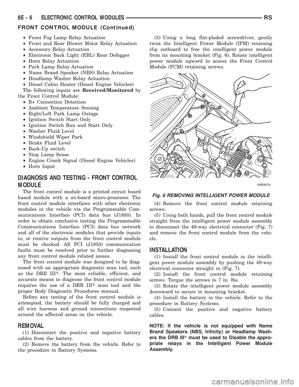
the procedure in Battery Systems.(3) Using a long flat-pladed screwdriver, gently
twist the Intelligent Power Module (IPM) retaining
clip outboard to free the intelligent power module
from its mounting bracket (Fig. 6). Rotate intelligent
power module upward to access the Front Control
Module (FCM) retaining screws.
(4) Remove the front control module retaining
screws.
(5) Using both hands, pull the front control module
straight from the intelligent power module assembly
to disconnect the 49-way electrical connector (Fig. 7)
and remove the front control module from the vehi-
cle.
INSTALLATION
(1) Install the front control module in the intelli-
gent power module assembly by pushing the 49-way
electrical connector straight in (Fig. 7).
(2) Install the front control module retaining
screws. Torque the screws to 7 in. lbs.
(3) Rotate the intelligent power module assembly
downward to secure in mounting bracket.
(4) Install the battery in the vehicle. Refer to the
procedure in Battery Systems.
(5) Connect the positive and negative battery
cables.
NOTE: If the vehicle is not equipped with Name
Brand Speakers (NBS, Infinity) or Headlamp Wash-
ers the DRB IIITmust be used to Disable the appro-
priate relays in the Intelligent Power Module
Assembly.
Fig. 6 REMOVING INTELLIGENT POWER MODULE
8E - 6 ELECTRONIC CONTROL MODULESRS
FRONT CONTROL MODULE (Continued)
Page 1832 of 4284
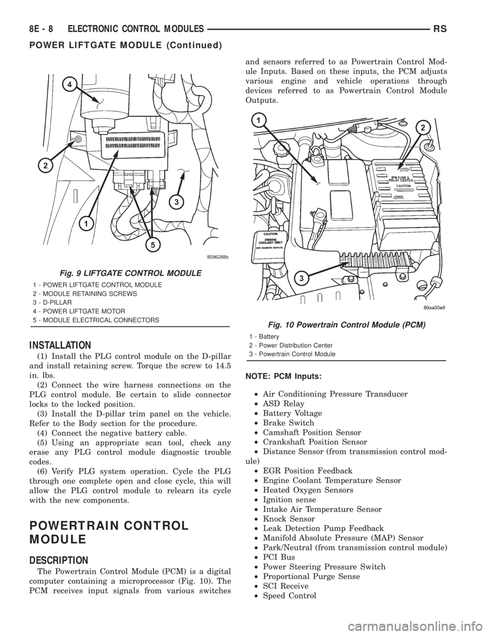
INSTALLATION
(1) Install the PLG control module on the D-pillar
and install retaining screw. Torque the screw to 14.5
in. lbs.
(2) Connect the wire harness connections on the
PLG control module. Be certain to slide connector
locks to the locked position.
(3) Install the D-pillar trim panel on the vehicle.
Refer to the Body section for the procedure.
(4) Connect the negative battery cable.
(5) Using an appropriate scan tool, check any
erase any PLG control module diagnostic trouble
codes.
(6) Verify PLG system operation. Cycle the PLG
through one complete open and close cycle, this will
allow the PLG control module to relearn its cycle
with the new components.
POWERTRAIN CONTROL
MODULE
DESCRIPTION
The Powertrain Control Module (PCM) is a digital
computer containing a microprocessor (Fig. 10). The
PCM receives input signals from various switchesand sensors referred to as Powertrain Control Mod-
ule Inputs. Based on these inputs, the PCM adjusts
various engine and vehicle operations through
devices referred to as Powertrain Control Module
Outputs.
NOTE: PCM Inputs:
²Air Conditioning Pressure Transducer
²ASD Relay
²Battery Voltage
²Brake Switch
²Camshaft Position Sensor
²Crankshaft Position Sensor
²Distance Sensor (from transmission control mod-
ule)
²EGR Position Feedback
²Engine Coolant Temperature Sensor
²Heated Oxygen Sensors
²Ignition sense
²Intake Air Temperature Sensor
²Knock Sensor
²Leak Detection Pump Feedback
²Manifold Absolute Pressure (MAP) Sensor
²Park/Neutral (from transmission control module)
²PCI Bus
²Power Steering Pressure Switch
²Proportional Purge Sense
²SCI Receive
²Speed Control
Fig. 9 LIFTGATE CONTROL MODULE
1 - POWER LIFTGATE CONTROL MODULE
2 - MODULE RETAINING SCREWS
3 - D-PILLAR
4 - POWER LIFTGATE MOTOR
5 - MODULE ELECTRICAL CONNECTORS
Fig. 10 Powertrain Control Module (PCM)
1 - Battery
2 - Power Distribution Center
3 - Powertrain Control Module
8E - 8 ELECTRONIC CONTROL MODULESRS
POWER LIFTGATE MODULE (Continued)
Page 1834 of 4284
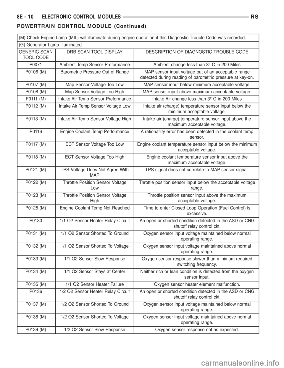
(M) Check Engine Lamp (MIL) will illuminate during engine operation if this Diagnostic Trouble Code was recorded.
(G) Generator Lamp Illuminated
GENERIC SCAN
TOOL CODEDRB SCAN TOOL DISPLAY DESCRIPTION OF DIAGNOSTIC TROUBLE CODE
P0071 Ambient Temp Sensor Preformance Ambient change less than 3É C in 200 Miles
P0106 (M) Barometric Pressure Out of Range MAP sensor input voltage out of an acceptable range
detected during reading of barometric pressure at key-on.
P0107 (M) Map Sensor Voltage Too Low MAP sensor input below minimum acceptable voltage.
P0108 (M) Map Sensor Voltage Too High MAP sensor input above maximum acceptable voltage.
P0111 (M) Intake Air Temp Sensor Preformance Intake Air change less than 3É C in 200 Miles
P0112 (M) Intake Air Temp Sensor Voltage Low Intake air (charge) temperature sensor input below the
minimum acceptable voltage.
P0113 (M) Intake Air Temp Sensor Voltage High Intake air (charge) temperature sensor input above the
maximum acceptable voltage.
P0116 Engine Coolant Temp Performance A rationatilty error has been detected in the coolant temp
sensor.
P0117 (M) ECT Sensor Voltage Too Low Engine coolant temperature sensor input below the minimum
acceptable voltage.
P0118 (M) ECT Sensor Voltage Too High Engine coolant temperature sensor input above the
maximum acceptable voltage.
P0121 (M) TPS Voltage Does Not Agree With
MAPTPS signal does not correlate to MAP sensor signal.
P0122 (M) Throttle Position Sensor Voltage
LowThrottle position sensor input below the acceptable voltage
range.
P0123 (M) Throttle Position Sensor Voltage
HighThrottle position sensor input above the maximum
acceptable voltage.
P0125 (M) Engine Coolant Temp Not Reached Time to enter Closed Loop Operation (Fuel Control) is
excessive.
P0130 1/1 O2 Sensor Heater Relay Circuit An open or shorted condition detected in the ASD or CNG
shutoff relay control ckt.
P0131 (M) 1/1 O2 Sensor Shorted To Ground Oxygen sensor input voltage maintained below normal
operating range.
P0132 (M) 1/1 O2 Sensor Shorted To Voltage Oxygen sensor input voltage maintained above normal
operating range.
P0133 (M) 1/1 O2 Sensor Slow Response Oxygen sensor response slower than minimum required
switching frequency.
P0134 (M) 1/1 O2 Sensor Stays at Center Neither rich or lean condition is detected from the oxygen
sensor input.
P0135 (M) 1/1 O2 Sensor Heater Failure Oxygen sensor heater element malfunction.
P0136 1/2 O2 Sensor Heater Relay Circuit An open or shorted condition detected in the ASD or CNG
shutoff relay control ckt.
P0137 (M) 1/2 O2 Sensor Shorted To Ground Oxygen sensor input voltage maintained below normal
operating range.
P0138 (M) 1/2 O2 Sensor Shorted To Voltage Oxygen sensor input voltage maintained above normal
operating range.
P0139 (M) 1/2 O2 Sensor Slow Response Oxygen sensor response not as expected.
8E - 10 ELECTRONIC CONTROL MODULESRS
POWERTRAIN CONTROL MODULE (Continued)
Page 1835 of 4284
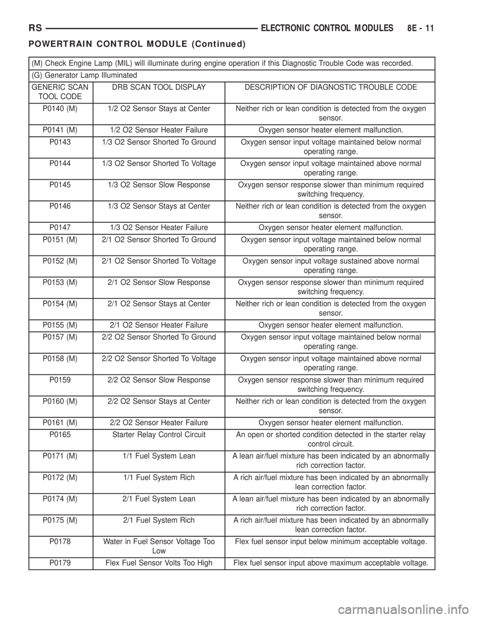
(M) Check Engine Lamp (MIL) will illuminate during engine operation if this Diagnostic Trouble Code was recorded.
(G) Generator Lamp Illuminated
GENERIC SCAN
TOOL CODEDRB SCAN TOOL DISPLAY DESCRIPTION OF DIAGNOSTIC TROUBLE CODE
P0140 (M) 1/2 O2 Sensor Stays at Center Neither rich or lean condition is detected from the oxygen
sensor.
P0141 (M) 1/2 O2 Sensor Heater Failure Oxygen sensor heater element malfunction.
P0143 1/3 O2 Sensor Shorted To Ground Oxygen sensor input voltage maintained below normal
operating range.
P0144 1/3 O2 Sensor Shorted To Voltage Oxygen sensor input voltage maintained above normal
operating range.
P0145 1/3 O2 Sensor Slow Response Oxygen sensor response slower than minimum required
switching frequency.
P0146 1/3 O2 Sensor Stays at Center Neither rich or lean condition is detected from the oxygen
sensor.
P0147 1/3 O2 Sensor Heater Failure Oxygen sensor heater element malfunction.
P0151 (M) 2/1 O2 Sensor Shorted To Ground Oxygen sensor input voltage maintained below normal
operating range.
P0152 (M) 2/1 O2 Sensor Shorted To Voltage Oxygen sensor input voltage sustained above normal
operating range.
P0153 (M) 2/1 O2 Sensor Slow Response Oxygen sensor response slower than minimum required
switching frequency.
P0154 (M) 2/1 O2 Sensor Stays at Center Neither rich or lean condition is detected from the oxygen
sensor.
P0155 (M) 2/1 O2 Sensor Heater Failure Oxygen sensor heater element malfunction.
P0157 (M) 2/2 O2 Sensor Shorted To Ground Oxygen sensor input voltage maintained below normal
operating range.
P0158 (M) 2/2 O2 Sensor Shorted To Voltage Oxygen sensor input voltage maintained above normal
operating range.
P0159 2/2 O2 Sensor Slow Response Oxygen sensor response slower than minimum required
switching frequency.
P0160 (M) 2/2 O2 Sensor Stays at Center Neither rich or lean condition is detected from the oxygen
sensor.
P0161 (M) 2/2 O2 Sensor Heater Failure Oxygen sensor heater element malfunction.
P0165 Starter Relay Control Circuit An open or shorted condition detected in the starter relay
control circuit.
P0171 (M) 1/1 Fuel System Lean A lean air/fuel mixture has been indicated by an abnormally
rich correction factor.
P0172 (M) 1/1 Fuel System Rich A rich air/fuel mixture has been indicated by an abnormally
lean correction factor.
P0174 (M) 2/1 Fuel System Lean A lean air/fuel mixture has been indicated by an abnormally
rich correction factor.
P0175 (M) 2/1 Fuel System Rich A rich air/fuel mixture has been indicated by an abnormally
lean correction factor.
P0178 Water in Fuel Sensor Voltage Too
LowFlex fuel sensor input below minimum acceptable voltage.
P0179 Flex Fuel Sensor Volts Too High Flex fuel sensor input above maximum acceptable voltage.
RSELECTRONIC CONTROL MODULES8E-11
POWERTRAIN CONTROL MODULE (Continued)
Page 1836 of 4284
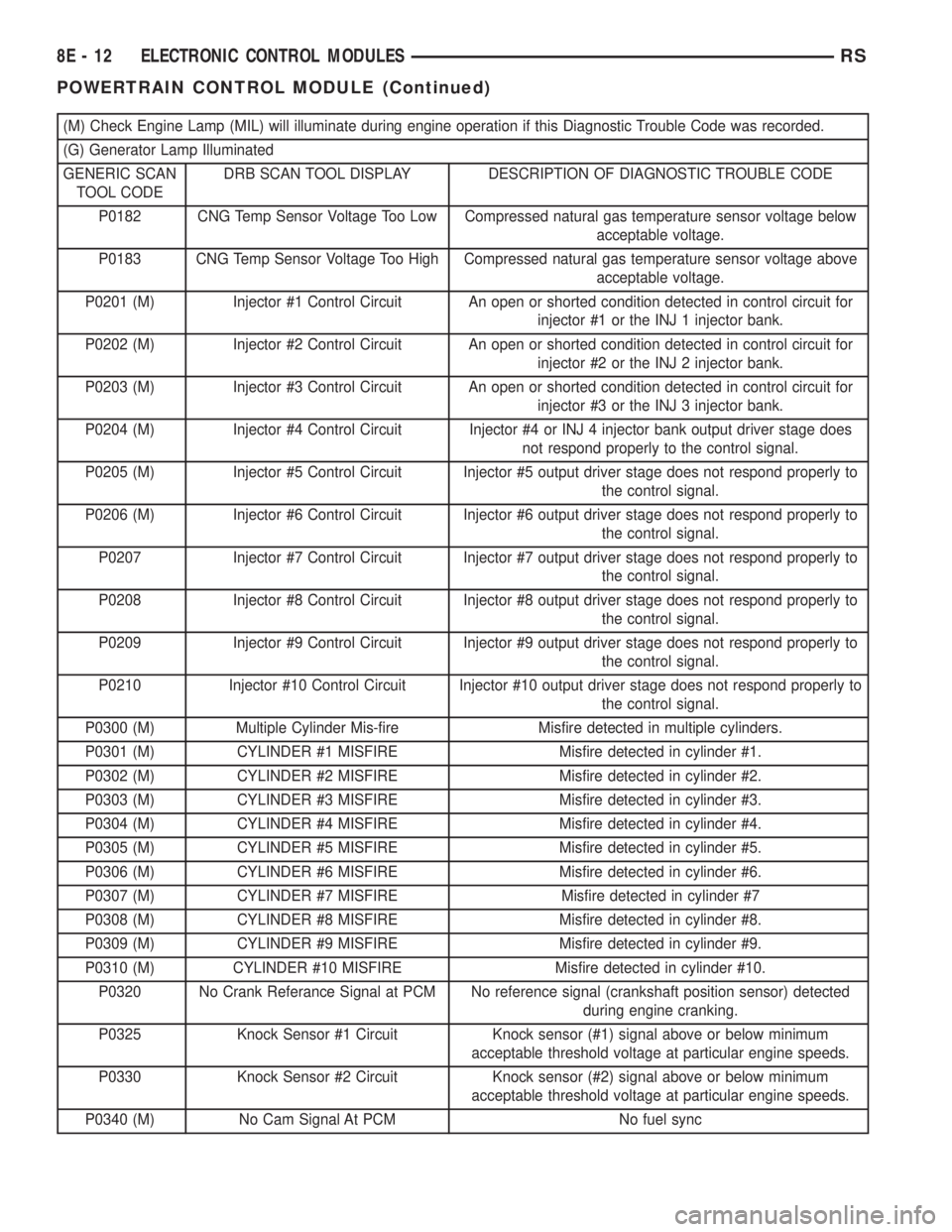
(M) Check Engine Lamp (MIL) will illuminate during engine operation if this Diagnostic Trouble Code was recorded.
(G) Generator Lamp Illuminated
GENERIC SCAN
TOOL CODEDRB SCAN TOOL DISPLAY DESCRIPTION OF DIAGNOSTIC TROUBLE CODE
P0182 CNG Temp Sensor Voltage Too Low Compressed natural gas temperature sensor voltage below
acceptable voltage.
P0183 CNG Temp Sensor Voltage Too High Compressed natural gas temperature sensor voltage above
acceptable voltage.
P0201 (M) Injector #1 Control Circuit An open or shorted condition detected in control circuit for
injector #1 or the INJ 1 injector bank.
P0202 (M) Injector #2 Control Circuit An open or shorted condition detected in control circuit for
injector #2 or the INJ 2 injector bank.
P0203 (M) Injector #3 Control Circuit An open or shorted condition detected in control circuit for
injector #3 or the INJ 3 injector bank.
P0204 (M) Injector #4 Control Circuit Injector #4 or INJ 4 injector bank output driver stage does
not respond properly to the control signal.
P0205 (M) Injector #5 Control Circuit Injector #5 output driver stage does not respond properly to
the control signal.
P0206 (M) Injector #6 Control Circuit Injector #6 output driver stage does not respond properly to
the control signal.
P0207 Injector #7 Control Circuit Injector #7 output driver stage does not respond properly to
the control signal.
P0208 Injector #8 Control Circuit Injector #8 output driver stage does not respond properly to
the control signal.
P0209 Injector #9 Control Circuit Injector #9 output driver stage does not respond properly to
the control signal.
P0210 Injector #10 Control Circuit Injector #10 output driver stage does not respond properly to
the control signal.
P0300 (M) Multiple Cylinder Mis-fire Misfire detected in multiple cylinders.
P0301 (M) CYLINDER #1 MISFIRE Misfire detected in cylinder #1.
P0302 (M) CYLINDER #2 MISFIRE Misfire detected in cylinder #2.
P0303 (M) CYLINDER #3 MISFIRE Misfire detected in cylinder #3.
P0304 (M) CYLINDER #4 MISFIRE Misfire detected in cylinder #4.
P0305 (M) CYLINDER #5 MISFIRE Misfire detected in cylinder #5.
P0306 (M) CYLINDER #6 MISFIRE Misfire detected in cylinder #6.
P0307 (M) CYLINDER #7 MISFIRE Misfire detected in cylinder #7
P0308 (M) CYLINDER #8 MISFIRE Misfire detected in cylinder #8.
P0309 (M) CYLINDER #9 MISFIRE Misfire detected in cylinder #9.
P0310 (M) CYLINDER #10 MISFIRE Misfire detected in cylinder #10.
P0320 No Crank Referance Signal at PCM No reference signal (crankshaft position sensor) detected
during engine cranking.
P0325 Knock Sensor #1 Circuit Knock sensor (#1) signal above or below minimum
acceptable threshold voltage at particular engine speeds.
P0330 Knock Sensor #2 Circuit Knock sensor (#2) signal above or below minimum
acceptable threshold voltage at particular engine speeds.
P0340 (M) No Cam Signal At PCM No fuel sync
8E - 12 ELECTRONIC CONTROL MODULESRS
POWERTRAIN CONTROL MODULE (Continued)