2001 CHRYSLER VOYAGER diagram
[x] Cancel search: diagramPage 1157 of 4284
TABLE OF CONTENTS - Continued
RIGHT REAR WHEEL SPEED SIGNAL FAILURE.............................26
SYSTEM OVERVOLTAGE................................................28
SYSTEM UNDERVOLTAGE...............................................30
VALVE POWER FEED FAILURE...........................................32
*BRAKE LAMP SWITCH..................................................35
*TRAC OFF INDICATOR NEVER/ALWAYS ON...............................36
*TRAC ON INDICATOR NEVER/ALWAYS ON................................39
VERIFICATION TESTS
VERIFICATION TESTS...................................................40
8.0 COMPONENT LOCATIONS...............................................41
8.1CONTROLLER ANTILOCK BRAKE (CAB)..............................41
8.2DATA LINK CONNECTOR...........................................41
8.3FUSES...........................................................42
8.4TRACTION CONTROL SWITCH......................................42
8.4.1TRACTION CONTROL INDICATORS...........................43
8.5WHEEL SPEED SENSORS..........................................43
8.5.1FRONT....................................................43
8.5.2REAR.....................................................44
8.5AWHEEL SPEED SENSOR CONNECTORS..............................44
8.5A.1FRONT....................................................44
8.5A.2REAR.....................................................45
8.6BRAKE LAMP SWITCH.............................................45
9.0 CONNECTOR PINOUTS.................................................47
CONTROLLER ANTILOCK BRAKE - BLACK 24 WAY..........................47
DATA LINK CONNECTOR - WHITE 16 WAY.................................47
DIAGNOSTIC JUNCTION PORT - BLACK 16 WAY............................48
INTELLIGENT POWER MODULE C4 - GRAY 10 WAY.........................48
LEFT FRONT WHEEL SPEED SENSOR - BLACK 2 WAY......................48
LEFT FRONT WHEEL SPEED SENSOR CONNECTOR (SENSOR SIDE)-2WAY..49
LEFT REAR WHEEL SPEED SENSOR - BLACK 2 WAY........................49
LEFT REAR WHEEL SPEED SENSOR CONNECTOR (SENSOR SIDE)-2WAY ...49
FUSES (IPM)...........................................................51
PUMP MOTOR CONNECTOR-2WAY.....................................52
RIGHT FRONT WHEEL SPEED SENSOR - GRAY 2 WAY......................52
RIGHT FRONT WHEEL SPEED SENSOR CONNECTOR
(SENSOR SIDE)-2WAY.................................................52
RIGHT REAR WHEEL SPEED SENSOR - BLACK 2 WAY......................52
RIGHT REAR WHEEL SPEED SENSOR CONNECTOR (SENSOR SIDE)-2WAY..53
TRACTION CONTROL SWITCH - BLACK 2 WAY.............................53
10.0 SCHEMATIC DIAGRAMS.................................................55
TEVES MARK 20 ANTILOCK BRAKE SYSTEM........................55
ii
Page 1212 of 4284
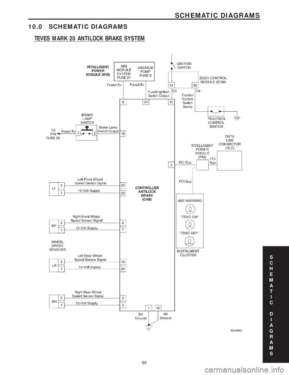
10.0 SCHEMATIC DIAGRAMS
TEVES MARK 20 ANTILOCK BRAKE SYSTEM
S
C
H
E
M
A
T
I
C
D
I
A
G
R
A
M
S
55
SCHEMATIC DIAGRAMS
Page 1219 of 4284
TABLE OF CONTENTS - Continued
A/C COMPRESSOR CLUTCH RELAY......................................242
ECM/PCM RELAY (DIESEL).............................................242
FUEL HEATER RELAY (DIESEL)..........................................242
LIFT PUMP RELAY (DIESEL).............................................242
STARTER MOTOR RELAY...............................................242
RADIATOR FAN NO. 1 (DIESEL) - GRAY 2 WAY.............................242
RADIATOR FAN NO. 2 (DIESEL) - GRAY 2 WAY.............................243
RADIATOR FAN RELAY NO. 1 (DIESEL) - BLUE 9 WAY......................243
RADIATOR FAN RELAY NO. 2 (DIESEL) - BLUE 9 WAY......................243
RADIATOR FAN RELAY NO. 3 (DIESEL) - BLUE 9 WAY......................243
RIGHT SPEED CONTROL SWITCH - WHITE 2 WAY.........................244
SENTRY KEY IMMOBILIZER MODULE - BLACK 6 WAY......................244
VEHICLE SPEED SENSOR (MTX/ATX) - BLACK 3 WAY......................244
WATER IN FUEL SENSOR (DIESEL) - BLACK 2 WAY........................244
10.0 SCHEMATIC DIAGRAMS................................................245
10.12001 RG 2.5L TURBO DIESEL......................................245
11.0 CHARTS AND GRAPHS................................................247
vi
Page 1223 of 4284
check the shared circuits for possible problems
before continuing (i.e. Sensor Grounds or 5-Volt
Supply circuits). Refer to the appropriate wiring
diagrams to identify shared circuits.
MASS AIR FLOW SENSOR SIGNAL VOLTAGE
TOO HIGH
MASS AIR FLOW SENSOR SIGNAL VOLTAGE
TOO LOW
MASS AIR FLOW SENSOR SUPPLY VOLTAGE
TOO HIGH OR LOW
MASS AIR FLOW SENSOR PLAUSIBILITY
MASS AIR FLOW SENSOR SIGNAL PLAUSI-
BILITY POSITIVE AREA
BAROMETRIC PRESSURE CIRCUIT SIGNAL
VOLTAGE TOO HIGH
BAROMETRIC PRESSURE CIRCUIT SIGNAL
VOLTAGE TOO LOW
INTAKE AIR TEMP SENSOR SIGNAL VOLT-
AGE TOO HIGH
INTAKE AIR TEMP SENSOR SIGNAL VOLT-
AGE TOO LOW
ENGINE COOLANT TEMP SENSOR SIGNAL
VOLTAGE TOO HIGH
ENGINE COOLANT TEMP SENSOR SIGNAL
VOLTAGE TOO LOW
FUEL PRESS SENSOR CIRCUIT MALF SIG-
NAL VOLTAGE TOO HIGH
FUEL PRESS SENSOR CIRCUIT MALF SIG-
NAL VOLTAGE TOO LOW
FUEL PRESS SENSOR CIRCUIT MALF SUP-
PLY VOLTAGE TOO HIGH OR LOW
OIL TEMP SENSOR CIRCUIT MALF SIGNAL
VOLTAGE TOO HIGH
OIL TEMP SENSOR CIRCUIT MALF SIGNAL
VOLTAGE TOO LOW
CYLINDER 1-INJECTOR CIRCUIT OVERCUR-
RENT HIGH SIDE
CYLINDER 1-INJECTOR CIRCUIT OVERCUR-
RENT LOW SIDE
CYLINDER 1-INJECTOR CIRCUIT LOAD
DROP
CYLINDER 1-INJECTOR CIRCUIT CURRENT
DECREASE
CYLINDER 2-INJECTOR CIRCUIT OVERCUR-
RENT HIGH SIDE
CYLINDER 2-INJECTOR CIRCUIT OVERCUR-
RENT LOW SIDE
CYLINDER 2-INJECTOR CIRCUIT LOAD
DROP
CYLINDER 2-INJECTOR CIRCUIT CURRENT
DECREASE
CYLINDER 3-INJECTOR CIRCUIT OVERCUR-
RENT HIGH SIDE
CYLINDER 3-INJECTOR CIRCUIT OVERCUR-
RENT LOW SIDE
CYLINDER 3-INJECTOR CIRCUIT LOAD
DROPCYLINDER 3-INJECTOR CIRCUIT CURRENT
DECREASE
CYLINDER 4-INJECTOR CIRCUIT OVERCUR-
RENT HIGH SIDE
CYLINDER 4-INJECTOR CIRCUIT OVERCUR-
RENT LOW SIDE
CYLINDER 4-INJECTOR CIRCUIT LOAD
DROP
CYLINDER 4-INJECTOR CIRCUIT CURRENT
DECREASE
BOOST PRESSURE SENSOR SIGNAL VOLT-
AGE TOO HIGH
BOOST PRESSURE SENSOR SIGNAL VOLT-
AGE TOO LOW
BOOST PRESSURE SENSOR SUPPLY VOLT-
AGE TOO HIGH OR LOW
BOOST PRESSURE SENSOR PLAUSIBILITY
CKP POSITION SENSOR CIRCUIT OVER-
SPEED RECOGNITION
CKP POSITION SENSOR CIRCUIT DYNAMIC
PLAUSIBILITY
CKP POSITION SENSOR CIRCUIT STATIC
PLAUSIBILITY
CMP POSITION SENSOR CIRCUIT CMP/CKP
SYNC FAILURE
CMP POSITION SENSOR CIRCUIT DYNAMIC
PLAUSIBILITY
CMP POSITION SENSOR CIRCUIT STATIC
PLAUSIBILITY
CMP POSITION SENSOR CIRCUIT SIGNAL
FREQUENCY TOO HIGH
CMP POSITION SENSOR CIRCUIT FUEL
SHUT-OFF ACTIVATED
GLOW PLUG CIRCUIT A SHORT CIRCUIT
GLOW PLUG CIRCUIT A OPEN CIRCUIT
EGR SOLENOID CIRCUIT OPEN CIRCUIT
EGR SOLENOID CIRCUIT SHORT CIRCUIT
EGR SOLENOID CIRCUIT IMPROPER FLOW
FAN 1 CONTROL CIRCUIT OPEN CIRCUIT
FAN 1 CONTROL CIRCUIT SHORT CIRCUIT
FAN 2 CONTROL CIRCUIT OPEN CIRCUIT
FAN 2 CONTROL CIRCUIT SHORT CIRCUIT
VEHICLE SPEED SENSOR SIGNAL VOLTAGE
TOO HIGH
VEHICLE SPEED SENSOR FREQUENCY TOO
HIGH
VEHICLE SPEED SENSOR HIGH LEVEL DU-
RATION
VEHICLE SPEED SENSOR PLAUSIBILITY
BATTERY TEMP SENSOR SIGNAL VOLTAGE
TOO HIGH
BATTERY TEMP SENSOR SIGNAL VOLTAGE
TOO LOW
OIL PRESS SENSOR CKT MALF PLAUSIBIL-
ITY
4
GENERAL INFORMATION
Page 1464 of 4284
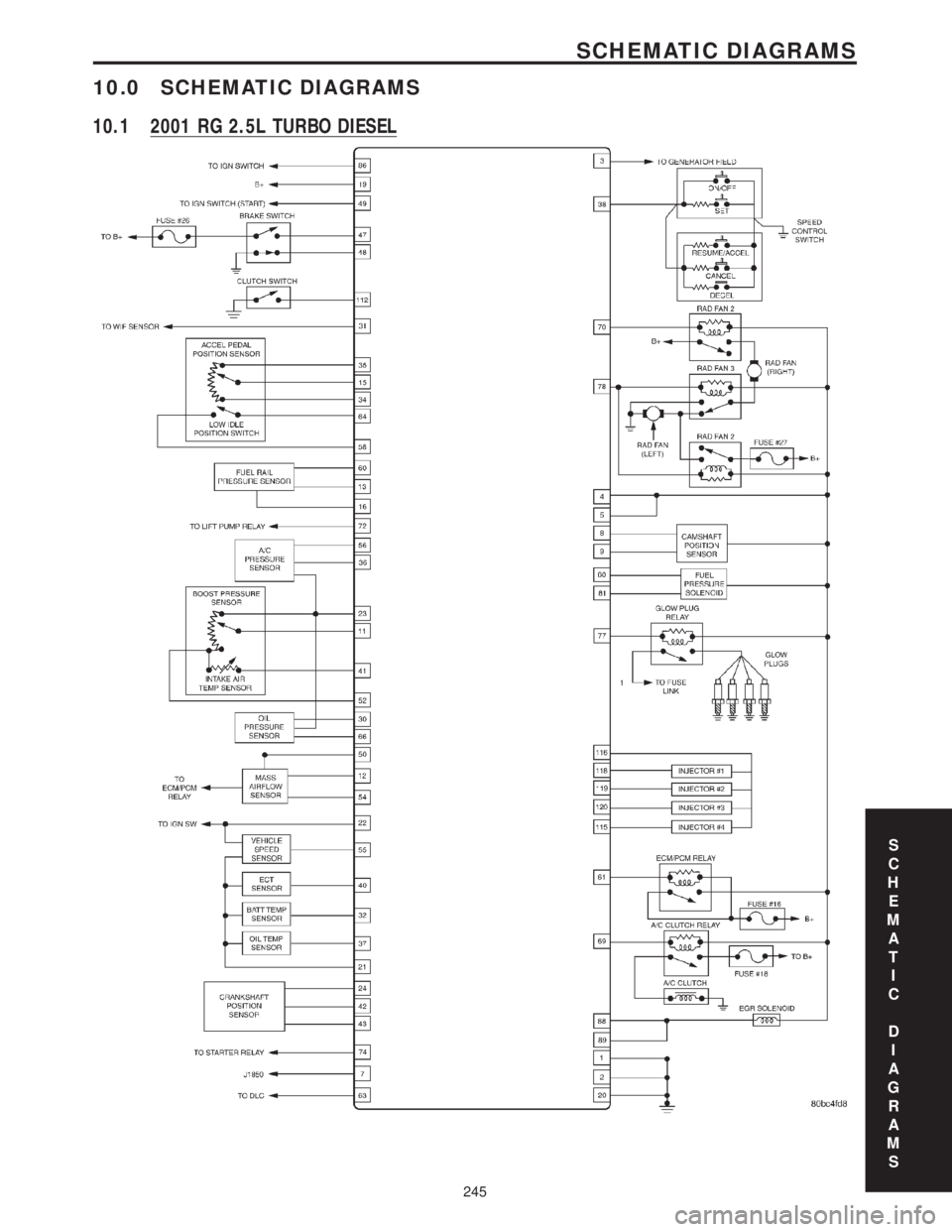
10.0 SCHEMATIC DIAGRAMS
10.1 2001 RG 2.5L TURBO DIESEL
S
C
H
E
M
A
T
I
C
D
I
A
G
R
A
M
S
245
SCHEMATIC DIAGRAMS
Page 1763 of 4284
REMOVAL
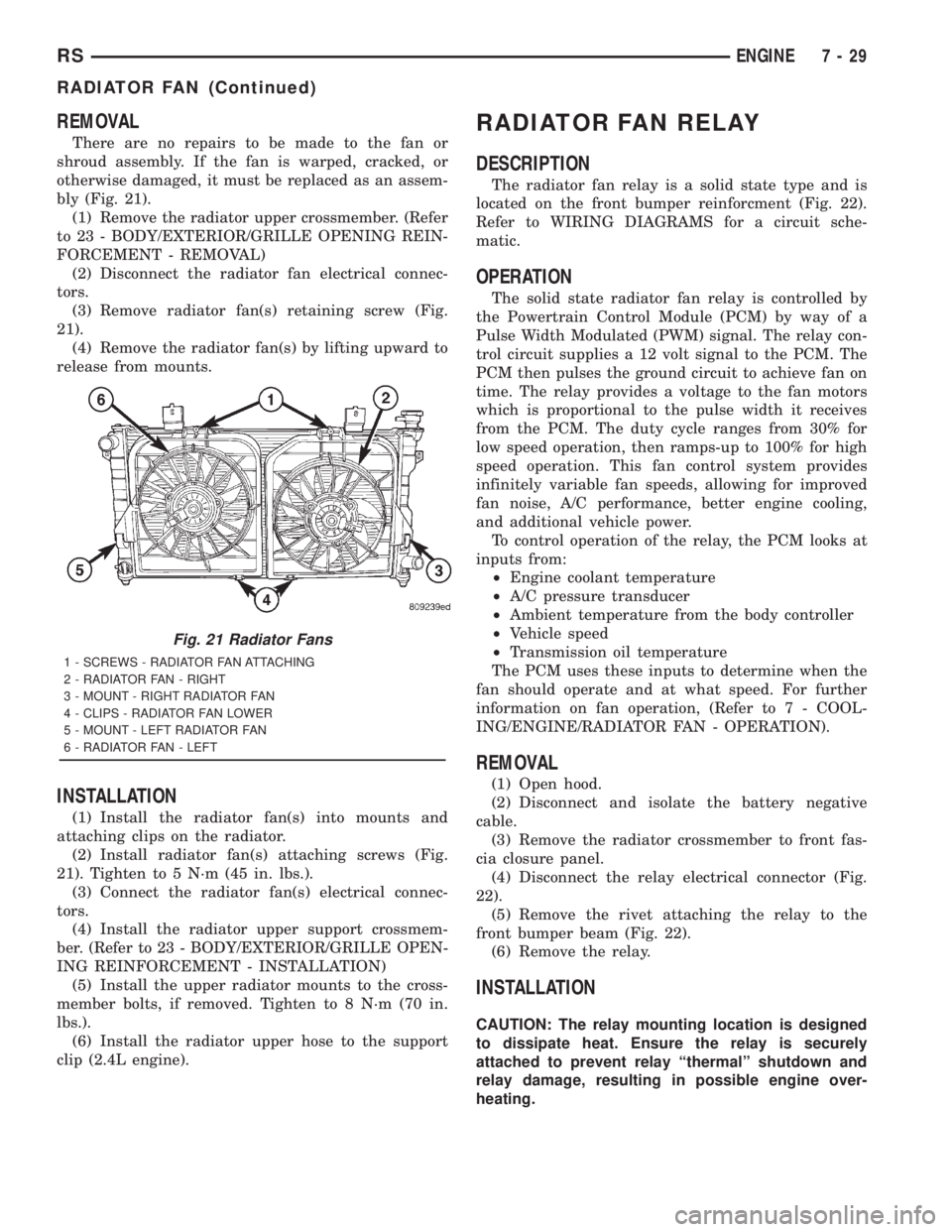
There are no repairs to be made to the fan or
shroud assembly. If the fan is warped, cracked, or
otherwise damaged, it must be replaced as an assem-
bly (Fig. 21).
(1) Remove the radiator upper crossmember. (Refer
to 23 - BODY/EXTERIOR/GRILLE OPENING REIN-
FORCEMENT - REMOVAL)
(2) Disconnect the radiator fan electrical connec-
tors.
(3) Remove radiator fan(s) retaining screw (Fig.
21).
(4) Remove the radiator fan(s) by lifting upward to
release from mounts.
INSTALLATION
(1) Install the radiator fan(s) into mounts and
attaching clips on the radiator.
(2) Install radiator fan(s) attaching screws (Fig.
21). Tighten to 5 N´m (45 in. lbs.).
(3) Connect the radiator fan(s) electrical connec-
tors.
(4) Install the radiator upper support crossmem-
ber. (Refer to 23 - BODY/EXTERIOR/GRILLE OPEN-
ING REINFORCEMENT - INSTALLATION)
(5) Install the upper radiator mounts to the cross-
member bolts, if removed. Tighten to 8 N´m (70 in.
lbs.).
(6) Install the radiator upper hose to the support
clip (2.4L engine).
RADIATOR FAN RELAY
DESCRIPTION
The radiator fan relay is a solid state type and is
located on the front bumper reinforcment (Fig. 22).
Refer to WIRING DIAGRAMS for a circuit sche-
matic.
OPERATION
The solid state radiator fan relay is controlled by
the Powertrain Control Module (PCM) by way of a
Pulse Width Modulated (PWM) signal. The relay con-
trol circuit supplies a 12 volt signal to the PCM. The
PCM then pulses the ground circuit to achieve fan on
time. The relay provides a voltage to the fan motors
which is proportional to the pulse width it receives
from the PCM. The duty cycle ranges from 30% for
low speed operation, then ramps-up to 100% for high
speed operation. This fan control system provides
infinitely variable fan speeds, allowing for improved
fan noise, A/C performance, better engine cooling,
and additional vehicle power.
To control operation of the relay, the PCM looks at
inputs from:
²Engine coolant temperature
²A/C pressure transducer
²Ambient temperature from the body controller
²Vehicle speed
²Transmission oil temperature
The PCM uses these inputs to determine when the
fan should operate and at what speed. For further
information on fan operation, (Refer to 7 - COOL-
ING/ENGINE/RADIATOR FAN - OPERATION).
REMOVAL
(1) Open hood.
(2) Disconnect and isolate the battery negative
cable.
(3) Remove the radiator crossmember to front fas-
cia closure panel.
(4) Disconnect the relay electrical connector (Fig.
22).
(5) Remove the rivet attaching the relay to the
front bumper beam (Fig. 22).
(6) Remove the relay.
INSTALLATION
CAUTION: The relay mounting location is designed
to dissipate heat. Ensure the relay is securely
attached to prevent relay ªthermalº shutdown and
relay damage, resulting in possible engine over-
heating.
Fig. 21 Radiator Fans
1 - SCREWS - RADIATOR FAN ATTACHING
2 - RADIATOR FAN - RIGHT
3 - MOUNT - RIGHT RADIATOR FAN
4 - CLIPS - RADIATOR FAN LOWER
5 - MOUNT - LEFT RADIATOR FAN
6 - RADIATOR FAN - LEFT
RSENGINE7-29
RADIATOR FAN (Continued)
Page 1812 of 4284
(4) Connect battery negative cable.
QUARTER PANEL SPEAKER
REMOVAL
(1) Disconnect and isolate the battery negative
cable.
(2) Remove speaker grill by prying away from trim
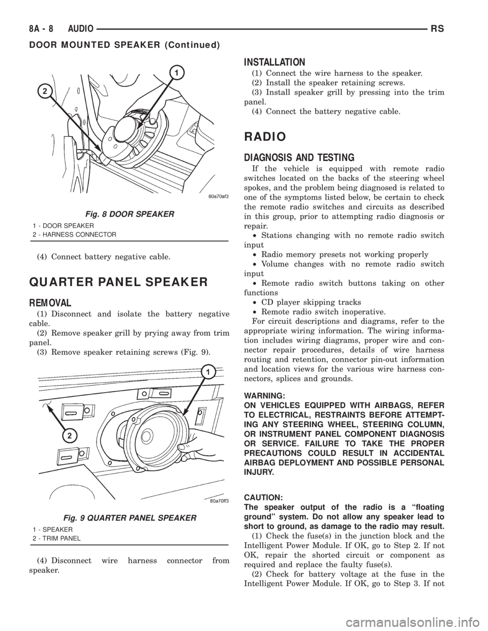
panel.
(3) Remove speaker retaining screws (Fig. 9).
(4) Disconnect wire harness connector from
speaker.
INSTALLATION
(1) Connect the wire harness to the speaker.
(2) Install the speaker retaining screws.
(3) Install speaker grill by pressing into the trim
panel.
(4) Connect the battery negative cable.
RADIO
DIAGNOSIS AND TESTING
If the vehicle is equipped with remote radio
switches located on the backs of the steering wheel
spokes, and the problem being diagnosed is related to
one of the symptoms listed below, be certain to check
the remote radio switches and circuits as described
in this group, prior to attempting radio diagnosis or
repair.
²Stations changing with no remote radio switch
input
²Radio memory presets not working properly
²Volume changes with no remote radio switch
input
²Remote radio switch buttons taking on other
functions
²CD player skipping tracks
²Remote radio switch inoperative.
For circuit descriptions and diagrams, refer to the
appropriate wiring information. The wiring informa-
tion includes wiring diagrams, proper wire and con-
nector repair procedures, details of wire harness
routing and retention, connector pin-out information
and location views for the various wire harness con-
nectors, splices and grounds.
WARNING:
ON VEHICLES EQUIPPED WITH AIRBAGS, REFER
TO ELECTRICAL, RESTRAINTS BEFORE ATTEMPT-
ING ANY STEERING WHEEL, STEERING COLUMN,
OR INSTRUMENT PANEL COMPONENT DIAGNOSIS
OR SERVICE. FAILURE TO TAKE THE PROPER
PRECAUTIONS COULD RESULT IN ACCIDENTAL
AIRBAG DEPLOYMENT AND POSSIBLE PERSONAL
INJURY.
CAUTION:
The speaker output of the radio is a ªfloating
groundº system. Do not allow any speaker lead to
short to ground, as damage to the radio may result.
(1) Check the fuse(s) in the junction block and the
Intelligent Power Module. If OK, go to Step 2. If not
OK, repair the shorted circuit or component as
required and replace the faulty fuse(s).
(2) Check for battery voltage at the fuse in the
Intelligent Power Module. If OK, go to Step 3. If not
Fig. 8 DOOR SPEAKER
1 - DOOR SPEAKER
2 - HARNESS CONNECTOR
Fig. 9 QUARTER PANEL SPEAKER
1 - SPEAKER
2 - TRIM PANEL
8A - 8 AUDIORS
DOOR MOUNTED SPEAKER (Continued)
Page 1817 of 4284
AUDIO
TABLE OF CONTENTS
page page
QUARTER GLASS INTEGRAL ANTENNA
DESCRIPTION............................1
OPERATION.............................1
DIAGNOSIS AND TESTING..................1
QUARTER GLASS INTEGRAL ANTENNA......1
ANTENNA MODULE
DESCRIPTION............................2OPERATION.............................2
DIAGNOSIS AND TESTING..................2
ANTENNA MODULE......................2
REMOVAL...............................2
INSTALLATION............................2
QUARTER GLASS INTEGRAL
ANTENNA
DESCRIPTION
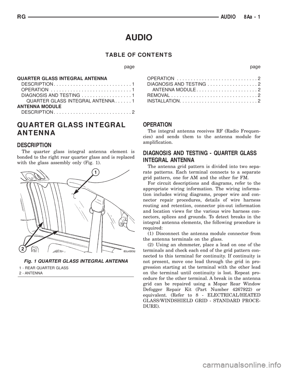
The quarter glass integral antenna element is
bonded to the right rear quarter glass and is replaced
with the glass assembly only (Fig. 1).
OPERATION
The integral antenna receives RF (Radio Frequen-
cies) and sends them to the antenna module for
amplification.
DIAGNOSIS AND TESTING - QUARTER GLASS
INTEGRAL ANTENNA
The antenna grid pattern is divided into two sepa-
rate patterns. Each terminal connects to a separate
grid pattern, one for AM and the other for FM.
For circuit descriptions and diagrams, refer to the
appropriate wiring information. The wiring informa-
tion includes wiring diagrams, proper wire and con-
nector repair procedures, details of wire harness
routing and retention, connector pin-out information
and location views for the various wire harness con-
nectors, splices and grounds. To detect breaks in the
integral antenna elements, the following procedure is
required:
(1) Disconnect the antenna module connector from
the antenna terminals on the glass.
(2) Using an ohmmeter, place a lead on one of the
terminals and check each end of the grid pattern con-
nected to this terminal for continuity. If continuity is
not present, move one lead through the grid in pro-
gression starting at the terminal with the other lead
on the terminal until continuity is lost. Repeat pro-
cedure for the other terminal. A break in the antenna
grid can be repaired using a Mopar Rear Window
Defogger Repair Kit (Part Number 4267922) or
equivalent. (Refer to 8 - ELECTRICAL/HEATED
GLASS/WINDSHIELD GRID - STANDARD PROCE-
DURE).
Fig. 1 QUARTER GLASS INTEGRAL ANTENNA
1 - REAR QUARTER GLASS
2 - ANTENNA
RGAUDIO8Aa-1