2001 CHRYSLER VOYAGER air condition
[x] Cancel search: air conditionPage 437 of 4284

Symptom:
*NO RESPONSE FROM ORC
POSSIBLE CAUSES
CHECKING FOR VOLTAGE AT ORC
ORC GROUND CIRCUIT OPEN
PCI BUS CIRCUIT OPEN
OCCUPANT RESTRAINT CONTROLLER
TEST ACTION APPLICABILITY
1NOTE: Check the FCM for DTC's. If DTC's are present, go to the appropriate
category and perform the DTC.
Ensure that the battery is fully charged.
WARNING: TURN THE IGNITION OFF, DISCONNECT THE BATTERY AND
WAIT TWO MINUTES BEFORE PROCEEDING.
Disconnect the Occupant Restraint Controller harness connector.
Turn the ignition on and then reconnect the Battery.
Using a 12-volt test light connected to ground, probe the ORC Run Only Driver
Circuit and the ORC Run/Start Driver Circuit at the ORC connector.
NOTE: One open circuit will not cause a NO RESPONSE condition.
Is the test light illuminated on both circuits?All
Ye s®Go To 2
No®Repair the ORC Run Only Driver and ORC Run/Start Driver
circuits for an open.
Perform AIRBAG VERIFICATION TEST - VER 1.
NOTE: When reconnecting airbag system components, the ignition must be
turned off and the battery must be disconnected.
2Ensure that the battery is fully charged.
WARNING: TURN THE IGNITION OFF, DISCONNECT THE BATTERY AND
WAIT TWO MINUTES BEFORE PROCEEDING.
Disconnect the Occupant Restraint Controller harness connector.
Measure the resistance between ground and the ground circuit.
Is the resistance below 5.0 ohms?All
Ye s®Go To 3
No®Repair the Ground circuit for an open.
Perform AIRBAG VERIFICATION TEST - VER 1.
When reconnecting Airbag system components, the ignition must be turned
off and the battery must be disconnected.
408
COMMUNICATION
Page 455 of 4284

Symptom:
*HOOD AJAR CIRCUIT OPEN
POSSIBLE CAUSES
HOOD AJAR SWITCH GROUND CIRCUIT OPEN
INTERMITTENT CONDITION
HOOD AJAR SWITCH
HOOD AJAR SWITCH SENSE CIRCUIT OPEN
BODY CONTROL MODULE INTERNAL MALFUNCTION
TEST ACTION APPLICABILITY
1 Open the Hood.
With the DRBIIItin Inputs/Outputs, read the HOOD AJAR SW state.
Does the DRBIIItdisplay CLOSED?All
Ye s®The condition that caused this symptom is currently not present.
Inspect the related wiring harness for a possible intermittent
condition. Look for any chafed, pierced, pinched or partially
broken wires.
Perform BODY VERIFICATION TEST - VER 1.
No®Go To 2
2 Disconnect the Hood Ajar switch connector.
Using a 12-volt Test Light connected to 12-volts, test the Ground circuit for
continuity.
Does the light illuminate?All
Ye s®Go To 3
No®Repair the Ground circuit for an open.
Perform BODY VERIFICATION TEST - VER 1.
3 Disconnect the Hood Ajar Switch connector.
With the DRBIIItin Inputs/Outputs, read the HOOD AJAR SW state.
Connect a jumper wire between Sense circuit and the Ground circuit.
Does the DRBIIItdisplay HOOD AJAR SW: CLOSED?All
Ye s®Replace the Hood Ajar Switch.
Perform BODY VERIFICATION TEST - VER 1.
No®Go To 4
4 Disconnect the Body Control Module C3 harness connector.
Disconnect the Hood Ajar Switch harness connector.
Measure the resistance of the Sense circuit.
Is the resistance below 5.0 ohms?All
Ye s®Replace the Body Control Module.
Perform BODY VERIFICATION TEST - VER 1.
No®Repair the Hood Ajar Switch Sense circuit for an open.
Perform BODY VERIFICATION TEST - VER 1.
426
DOOR AJAR
Page 457 of 4284

Symptom:
*LEFT FRONT DOOR AJAR SWITCH SENSE CIRCUIT OPEN
POSSIBLE CAUSES
INTERMITTENT CONDITION
LEFT FRONT DOOR AJAR SWITCH GROUND CIRCUIT OPEN
LEFT FRONT DOOR LOCK MOTOR/AJAR SWITCH
LEFT FRONT DOOR AJAR SWITCH SENSE CIRCUIT OPEN
BODY CONTROL MODULE INTERNAL MALFUNCTION
TEST ACTION APPLICABILITY
1 Open the driver door.
With the DRBIIItin Inputs/Outputs, read the DR DOOR AJAR SW state.
Does the DRBIIItdisplay CLOSED?All
Ye s®The condition that caused this symptom is currently not present.
Inspect the related wiring harness for a possible intermittent
condition. Look for any chafed, pierced, pinched or partially
broken wires.
Perform BODY VERIFICATION TEST - VER 1.
No®Go To 2
2 Disconnect the Left Front Door Lock Motor/Ajar switch connector.
Using a 12-volt Test Light connected to 12-volts, test the Ground circuit for
continuity.
Does the light illuminate?All
Ye s®Go To 3
No®Repair the Ground circuit for an open.
Perform BODY VERIFICATION TEST - VER 1.
3 Disconnect the Left Front Door Lock Motor/Ajar Switch connector.
With the DRBIIItin Inputs/Outputs, read the DR DOOR AJAR SW state.
Connect a jumper wire between Sense circuit and the Ground circuit.
Does the DRBIIItdisplay DR DOOR AJAR SW: CLOSED?All
Ye s®Replace the Left Front Door Lock Motor/Ajar Switch.
Perform BODY VERIFICATION TEST - VER 1.
No®Go To 4
4 Disconnect the Body Control Module C3 harness connector.
Disconnect the Left Front Door Lock Motor/Ajar Switch harness connector.
Measure the resistance of the Sense circuit.
Is the resistance below 5.0 ohms?All
Ye s®Replace the Body Control Module.
Perform BODY VERIFICATION TEST - VER 1.
No®Repair the Left Front Door Ajar Switch Sense circuit for an open.
Perform BODY VERIFICATION TEST - VER 1.
428
DOOR AJAR
Page 462 of 4284

Symptom:
*LIFTGATE AJAR CIRCUIT OPEN
POSSIBLE CAUSES
INTERMITTENT CONDITION
LIFTGATE AJAR SWITCH GROUND CIRCUIT OPEN
LIFTGATE AJAR SWITCH
LIFTGATE AJAR SWITCH SENSE CIRCUIT OPEN
BODY CONTROL MODULE INTERNAL MALFUNCTION
TEST ACTION APPLICABILITY
1 Open the Liftgate.
With the DRBIIItin Inputs/Outputs, read the LIFTGATE AJAR SW state.
Does the DRBIIItdisplay CLOSED?All
Ye s®The condition that caused this symptom is currently not present.
Inspect the related wiring harness for a possible intermittent
condition. Look for any chafed, pierced, pinched or partially
broken wires.
Perform BODY VERIFICATION TEST - VER 1.
No®Go To 2
2 Disconnect the Liftgate Ajar switch connector.
Using a 12-volt Test Light connected to 12-volts, test the Ground circuit for
continuity.
Does the light illuminate?All
Ye s®Go To 3
No®Repair the Ground circuit for an open.
Perform BODY VERIFICATION TEST - VER 1.
3 Disconnect the Liftgate Ajar Switch connector.
With the DRBIIItin Inputs/Outputs, read the LIFTGATE AJAR SW state.
Connect a jumper wire between Sense circuit and the Ground circuit.
Does the DRBIIItdisplay LIFTGATE AJAR SW: CLOSED?All
Ye s®Replace the Liftgate Ajar Switch.
Perform BODY VERIFICATION TEST - VER 1.
No®Go To 4
4 Disconnect the Body Control Module C3 harness connector.
Disconnect the Liftgate Ajar Switch harness connector.
Measure the resistance of the Sense circuit.
Is the resistance below 5.0 ohms?All
Ye s®Replace the Body Control Module.
Perform BODY VERIFICATION TEST - VER 1.
No®Repair the Liftgate Ajar Switch Sense circuit for an open.
Perform BODY VERIFICATION TEST - VER 1.
433
DOOR AJAR
Page 464 of 4284

Symptom:
*RIGHT FRONT DOOR AJAR SWITCH SENSE CIRCUIT OPEN
POSSIBLE CAUSES
INTERMITTENT CONDITION
RIGHT FRONT DOOR AJAR SWITCH GROUND CIRCUIT OPEN
RIGHT FRONT DOOR LOCK MOTOR/AJAR SWITCH
RIGHT FRONT DOOR AJAR SWITCH SENSE CIRCUIT OPEN
BODY CONTROL MODULE INTERNAL MALFUNCTION
TEST ACTION APPLICABILITY
1 Open the passenger door.
With the DRBIIItin Inputs/Outputs, read the PASS DOOR AJAR SW state.
Does the DRBIIItdisplay CLOSED?All
Ye s®The condition that caused this symptom is currently not present.
Inspect the related wiring harness for a possible intermittent
condition. Look for any chafed, pierced, pinched or partially
broken wires.
Perform BODY VERIFICATION TEST - VER 1.
No®Go To 2
2 Disconnect the Right Front Door Lock Motor/Ajar switch connector.
Using a 12-volt Test Light connected to 12-volts, test the Ground circuit for
continuity.
Does the light illuminate?All
Ye s®Go To 3
No®Repair the Ground circuit for an open.
Perform BODY VERIFICATION TEST - VER 1.
3 Disconnect the Right Front Door Lock Motor/Ajar Switch connector.
With the DRBIIItin Inputs/Outputs, read the PASS DOOR AJAR SW state.
Connect a jumper wire between Sense circuit and the Ground circuit.
Does the DRBIIItdisplay PASS DOOR AJAR SW: CLOSED?All
Ye s®Replace the Right Front Door Lock Motor/Ajar Switch.
Perform BODY VERIFICATION TEST - VER 1.
No®Go To 4
4 Disconnect the Body Control Module C3 harness connector.
Disconnect the Right Front Door Lock Motor/Ajar Switch harness connector.
Measure the resistance of the Sense circuit.
Is the resistance below 5.0 ohms?All
Ye s®Replace the Body Control Module.
Perform BODY VERIFICATION TEST - VER 1.
No®Repair the Right Front Door Ajar Switch Sense circuit for an
open.
Perform BODY VERIFICATION TEST - VER 1.
435
DOOR AJAR
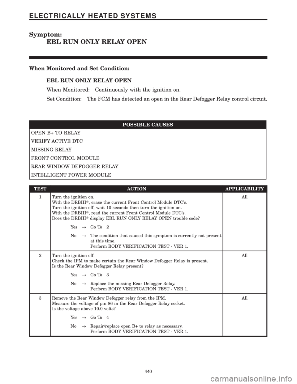
Page 469 of 4284

Symptom:
EBL RUN ONLY RELAY OPEN
When Monitored and Set Condition:
EBL RUN ONLY RELAY OPEN
When Monitored: Continuously with the ignition on.
Set Condition: The FCM has detected an open in the Rear Defogger Relay control circuit.
POSSIBLE CAUSES
OPEN B+ TO RELAY
VERIFY ACTIVE DTC
MISSING RELAY
FRONT CONTROL MODULE
REAR WINDOW DEFOGGER RELAY
INTELLIGENT POWER MODULE
TEST ACTION APPLICABILITY
1 Turn the ignition on.
With the DRBIIIt, erase the current Front Control Module DTC's.
Turn the ignition off, wait 10 seconds then turn the ignition on.
With the DRBIIIt, read the current Front Control Module DTC's.
Does the DRBIIItdisplay EBL RUN ONLY RELAY OPEN trouble code?All
Ye s®Go To 2
No®The condition that caused this symptom is currently not present
at this time.
Perform BODY VERIFICATION TEST - VER 1.
2 Turn the ignition off.
Check the IPM to make certain the Rear Window Defogger Relay is present.
Is the Rear Window Defogger Relay present?All
Ye s®Go To 3
No®Replace the missing Rear Defogger Relay.
Perform BODY VERIFICATION TEST - VER 1.
3 Remove the Rear Window Defogger relay from the IPM.
Measure the voltage of pin 86 in the Rear Defogger Relay socket.
Is the voltage above 10.0 volts?All
Ye s®Go To 4
No®Repair/replace open B+ to relay as necessary.
Perform BODY VERIFICATION TEST - VER 1.
440
ELECTRICALLY HEATED SYSTEMS
Page 472 of 4284

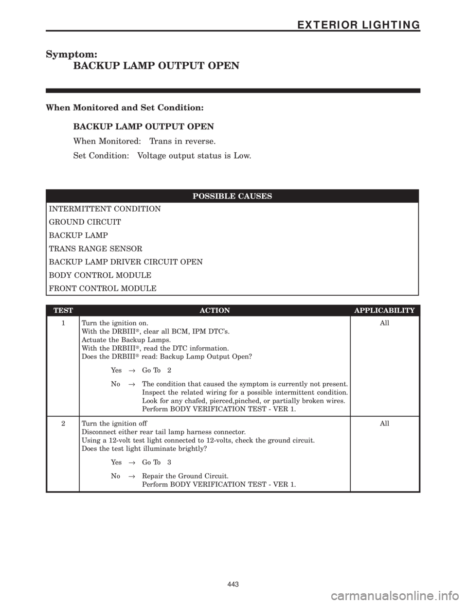
Symptom:
BACKUP LAMP OUTPUT OPEN
When Monitored and Set Condition:
BACKUP LAMP OUTPUT OPEN
When Monitored: Trans in reverse.
Set Condition: Voltage output status is Low.
POSSIBLE CAUSES
INTERMITTENT CONDITION
GROUND CIRCUIT
BACKUP LAMP
TRANS RANGE SENSOR
BACKUP LAMP DRIVER CIRCUIT OPEN
BODY CONTROL MODULE
FRONT CONTROL MODULE
TEST ACTION APPLICABILITY
1 Turn the ignition on.
With the DRBIIIt, clear all BCM, IPM DTC's.
Actuate the Backup Lamps.
With the DRBIIIt, read the DTC information.
Does the DRBIIItread: Backup Lamp Output Open?All
Ye s®Go To 2
No®The condition that caused the symptom is currently not present.
Inspect the related wiring for a possible intermittent condition.
Look for any chafed, pierced,pinched, or partially broken wires.
Perform BODY VERIFICATION TEST - VER 1.
2 Turn the ignition off
Disconnect either rear tail lamp harness connector.
Using a 12-volt test light connected to 12-volts, check the ground circuit.
Does the test light illuminate brightly?All
Ye s®Go To 3
No®Repair the Ground Circuit.
Perform BODY VERIFICATION TEST - VER 1.
443
EXTERIOR LIGHTING
Page 473 of 4284

TEST ACTION APPLICABILITY
3 Turn the ignition off.
Disconnect either rear tail lamp harness connector.
Turn the ignition on.
Engage the transmission to reverse.
Using a 12-volt test light connected to ground, check the Backup Lamps Output
circuit.
Does the test light illuminate brightly?All
Ye s®Replace the applicable Backup Lamp.
Perform BODY VERIFICATION TEST - VER 1.
No®Go To 4
4 Turn the ignition off.
Disconnect the IPM harness connector.
Measure the resistance of the Backup Lamp Output Circuit and ground.
Is the resistance below 5.0 ohms?All
Ye s®Refer to symptom list for problems related to Trans Range Sensor.
Perform BODY VERIFICATION TEST - VER 1.
No®Go To 5
5 Turn the ignition off.
Disconnect the Body Control Module harness connector.
Measure the resistance of the Backup Lamp Driver Circuit to ground.
Is the resistance above 5.0 ohms?All
Ye s®Repair the Backup Lamp Driver Circuit for an open condition.
Perform BODY VERIFICATION TEST - VER 1.
No®Go To 6
6 Turn the ignition off.
Disconnect the Body Control Module harness connector.
Disconnect the FCM from the IPM.
Measure the resistance of the Backup Lamp Driver Circuit and ground.
Is the resistance below 5.0 ohms?All
Ye s®Replace the Body Control Module.
Perform BODY VERIFICATION TEST - VER 1.
No®Replace the Front Control Module.
Perform BODY VERIFICATION TEST - VER 1.
444
EXTERIOR LIGHTING
BACKUP LAMP OUTPUT OPEN ÐContinued