2001 CHRYSLER VOYAGER keyless
[x] Cancel search: keylessPage 790 of 4284

Symptom:
RKE PROGRAM LINE OUTPUT OPEN
When Monitored and Set Condition:
RKE PROGRAM LINE OUTPUT OPEN
When Monitored: With ignition in the RUN position.
Set Condition: When the BCM senses an open or short to ground signal on the RKE
Module Program Enable circuit for longer than 0.125 msec.
POSSIBLE CAUSES
DTC PRESENT
BODY CONTROL MODULE - RKE MODULE PROGRAM ENABLE CIRCUIT OPEN OR SHORT TO
GROUND
RKE MODULE PROGRAM ENABLE WIRE OPEN
RKE MODULE PROGRAM ENABLE WIRE SHORT TO GROUND
RKE MODULE - PROGRAM ENABLE CIRCUIT OPEN
TEST ACTION APPLICABILITY
1 Turn the ignition on.
With the DRBIIIt, record and erase DTC's.
With the DRBIIIt, read DTCs.
Operate the RKE transmitter while monitoring the DRBIII.
Does the DRBIIItdisplay RKE PROGRAM LINE OUTPUT OPEN?All
Ye s®Go To 2
No®Using the wiring diagram/schematic as a guide, inspect the
wiring and connectors for an intermittent condition.
Perform BODY VERIFICATION TEST - VER 1.
2 Disconnect the Body Control Module C4 connector.
Measure the voltage of the RKE Module Program Enable circuit between ground and
the BCM C4 connector.
Is the voltage between 10.2 and 11.8 volts?All
Ye s®Replace the Body Control Module.
Perform BODY VERIFICATION TEST - VER 1.
No®Go To 3
3 Turn the ignition off.
Disconnect the Remote Keyless Entry Module connector.
Disconnect the Body Control Module C4 connector.
Measure the resistance of the RKE Module Program Enable circuit between the RKE
Module connector and the BCM C4 connector.
Is the resistance below 5.0 ohms?All
Ye s®Go To 4
No®Repair the RKE Module Program Enable wire for an open
Perform BODY VERIFICATION TEST - VER 1.
761
POWER DOOR LOCKS/RKE
Page 791 of 4284

TEST ACTION APPLICABILITY
4 Turn the ignition off.
Disconnect the Remote Keyless Entry Module connector.
Disconnect the Body Control Module C4 connector.
Measure the resistance of the RKE Module Program Enable circuit to ground.
Is the resistance below 1000.0 ohms?All
Ye s®Repair the RKE Module Program Enable wire for a short to
ground.
Perform BODY VERIFICATION TEST - VER 1.
No®Go To 5
5 If there are no possible causes remaining, view repair. All
Repair
Replace the Remote Keyless Entry Module.
Perform BODY VERIFICATION TEST - VER 1.
762
POWER DOOR LOCKS/RKE
RKE PROGRAM LINE OUTPUT OPEN ÐContinued
Page 792 of 4284

Symptom:
RKE PROGRAM LINE OUTPUT SHORT
When Monitored and Set Condition:
RKE PROGRAM LINE OUTPUT SHORT
When Monitored: With ignition in the RUN position.
Set Condition: When the BCM senses an over current on the RKE Module Program
Enable circuit and the RKE is in PROGRAM or DIAGNOSTIC mode.
POSSIBLE CAUSES
DTC PRESENT
REMOTE KEYLESS ENTRY MODULE - RKE MODULE PROGRAM ENABLE CIRCUIT SHORT TO
VOLTAGE
RKE MODULE PROGRAM ENABLE WIRE SHORT TO VOLTAGE
BODY CONTROL MODULE - SHORT TO VOLTAGE
TEST ACTION APPLICABILITY
1 Turn the ignition on.
With the DRBIIIt, record and erase DTC's.
With the DRBIIIt, enter PROGRAM RKE.
With the DRBIIIt, read DTCs.
Does the DRBIIItdisplay RKE PROGRAM LINE OUTPUT SHORT?All
Ye s®Go To 2
No®Using the wiring diagram/schematic as a guide, inspect the
wiring and connectors for an intermittent condition.
Perform BODY VERIFICATION TEST - VER 1.
2 Disconnect the Remote Keyless Entry Module connector.
With the DRBIIIt, erase DTCs.
Cycle the ignition key and wait 30 seconds.
With the DRBIIIt, read DTCs.
Does the DRBIIItdisplay RKE PROGRAM LINE OUTPUT OPEN?All
No®Go To 3
Ye s®Replace the Remote Keyless Entry Module.
Perform BODY VERIFICATION TEST - VER 1.
3 Disconnect the Remote Keyless Entry Module connector.
Disconnect the Body Control Module C4 connector.
Turn the ignition on.
Measure the voltage between RKE Module Program Enable circuit and ground.
Is there any voltage present?All
Ye s®Repair the RKE Module Program Enable wire for a short to
voltage.
Perform BODY VERIFICATION TEST - VER 1.
No®Replace the Body Control Module.
Perform BODY VERIFICATION TEST - VER 1.
763
POWER DOOR LOCKS/RKE
Page 1035 of 4284
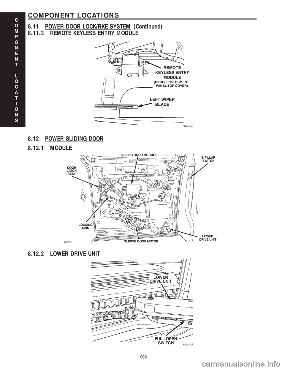
8.11.3 REMOTE KEYLESS ENTRY MODULE
8.12 POWER SLIDING DOOR
8.12.1 MODULE
8.12.2 LOWER DRIVE UNIT
C
O
M
P
O
N
E
N
T
L
O
C
A
T
I
O
N
S
1006
COMPONENT LOCATIONS
8.11 POWER DOOR LOCK/RKE SYSTEM (Continued)
Page 1045 of 4284
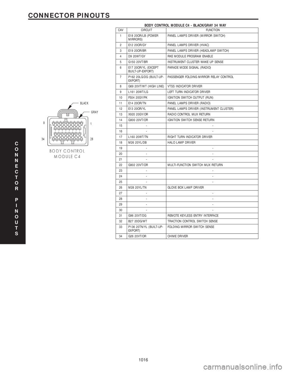
BODY CONTROL MODULE C4 - BLACK/GRAY 34 WAYCAV CIRCUIT FUNCTION
1 E18 20OR/LB (POWER
MIRRORS)PANEL LAMPS DRIVER (MIRROR SWITCH)
2 E12 20OR/GY PANEL LAMPS DRIVER (HVAC)
3 E19 20OR/BR PANEL LAMPS DRIVER (HEADLAMP SWITCH)
4 D9 20WT/GY RKE MODULE PROGRAM ENABLE
5 G150 20VT/BR INSTRUMENT CLUSTER WAKE UP SENSE
6 E17 20OR/YL (EXCEPT
BUILT-UP-EXPORT)PARADE MODE SIGNAL (RADIO)
7 P162 20LG/DG (BUILT-UP-
EXPORT)PASSENGER FOLDING MIRROR RELAY CONTROL
8 G69 20VT/WT (HIGH LINE) VTSS INDICATOR DRIVER
9 L161 20WT/LG LEFT TURN INDICATOR DRIVER
10 F504 20GY/PK IGNITION SWITCH OUTPUT (RUN)
11 E14 20OR/TN PANEL LAMPS DRIVER (RADIO)
12 E13 20OR/YL PANEL LAMPS DRIVER (INSTRUMENT CLUSTER)
13 X920 20GY/OR RADIO CONTROL MUX RETURN
14 G900 20VT/OR IGNITION SWITCH SENSE RETURN
15 - -
16 - -
17 L160 20WT/TN RIGHT TURN INDICATOR DRIVER
18 M26 20YL/DB HALO LAMP DRIVER
19 - -
20 - -
21 - -
22 G902 20VT/OR MULTI-FUNCTION SWITCH MUX RETURN
23 - -
24 - -
25 - -
26 M28 20YL/TN GLOVE BOX LAMP DRIVER
27 - -
28 - -
29 - -
30 - -
31 G96 20VT/DG REMOTE KEYLESS ENTRY INTERFACE
32 B27 20DG/WT TRACTION CONTROL SWITCH SENSE
33 P136 20TN/YL (BUILT-UP-
EXPORT)FOLDING MIRROR SWITCH SENSE
34 G26 20VT/OR CHIME DRIVER
C
O
N
N
E
C
T
O
R
P
I
N
O
U
T
S
1016
CONNECTOR PINOUTS
Page 1106 of 4284
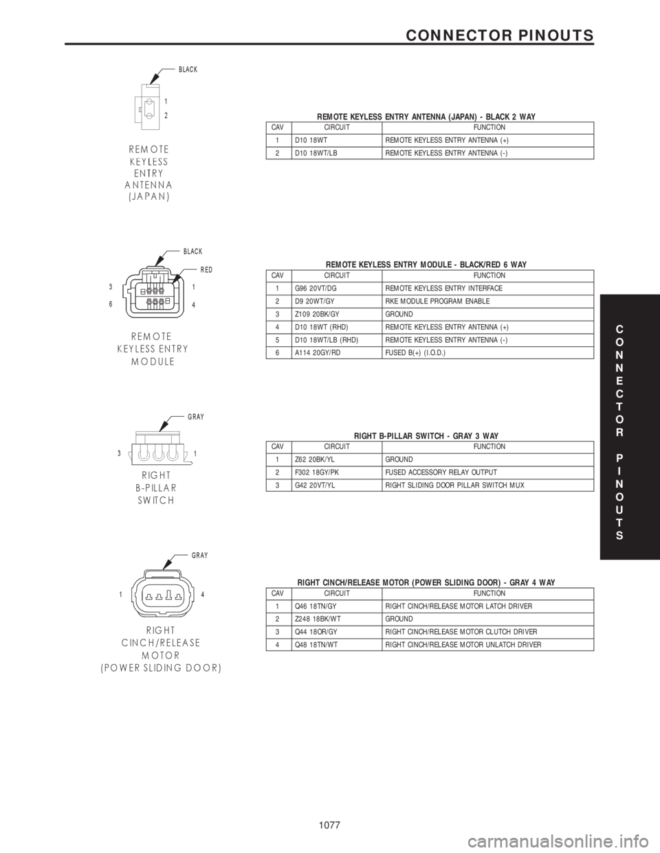
REMOTE KEYLESS ENTRY ANTENNA (JAPAN) - BLACK 2 WAYCAV CIRCUIT FUNCTION
1 D10 18WT REMOTE KEYLESS ENTRY ANTENNA (+)
2 D10 18WT/LB REMOTE KEYLESS ENTRY ANTENNA (-)
REMOTE KEYLESS ENTRY MODULE - BLACK/RED 6 WAYCAV CIRCUIT FUNCTION
1 G96 20VT/DG REMOTE KEYLESS ENTRY INTERFACE
2 D9 20WT/GY RKE MODULE PROGRAM ENABLE
3 Z109 20BK/GY GROUND
4 D10 18WT (RHD) REMOTE KEYLESS ENTRY ANTENNA (+)
5 D10 18WT/LB (RHD) REMOTE KEYLESS ENTRY ANTENNA (-)
6 A114 20GY/RD FUSED B(+) (I.O.D.)
RIGHT B-PILLAR SWITCH - GRAY 3 WAYCAV CIRCUIT FUNCTION
1 Z62 20BK/YL GROUND
2 F302 18GY/PK FUSED ACCESSORY RELAY OUTPUT
3 G42 20VT/YL RIGHT SLIDING DOOR PILLAR SWITCH MUX
RIGHT CINCH/RELEASE MOTOR (POWER SLIDING DOOR) - GRAY 4 WAYCAV CIRCUIT FUNCTION
1 Q46 18TN/GY RIGHT CINCH/RELEASE MOTOR LATCH DRIVER
2 Z248 18BK/WT GROUND
3 Q44 18OR/GY RIGHT CINCH/RELEASE MOTOR CLUTCH DRIVER
4 Q48 18TN/WT RIGHT CINCH/RELEASE MOTOR UNLATCH DRIVER
C
O
N
N
E
C
T
O
R
P
I
N
O
U
T
S
1077
CONNECTOR PINOUTS
Page 1904 of 4284
²Remote Keyless Entry Module (RKE)- Refer
toRemote Keyless Entry Modulein Power Locks
for more information.
²Electronic Vehicle Information Center
(EVIC)- Refer toElectronic Vehicle Information
Centerin Overhead Console for more information.
²Heated Seat Module (HSM)- Refer toHeated
Seat Modulein Electronic Control Modules for more
information.
²Memory Heated Seat Module (MHSM)-If
the vehicle is equipped with the Memory System,
refer toMemory Seat Mirror Module (MSMM)in
Electronic Control Modules for more information.
Refer toWiring Diagramsfor complete circuit
diagrams. Following are general descriptions of the
major components in the heated seat system.
OPERATION
The heated seat system will only operate when the
ignition switch is in the On position, and the surface
temperature at the front seat heating element sen-
sors is below the designed temperature set points of
the system. The heated seat system will not operate
in ambient temperatures greater than about 41É C
(105É F). The front seat heating elements and sensors
are hard wired to the Heated Seat Module (HSM) or
the Memory Heated Seat Module (MHSM).
The heated seat switches are hard wired to the
Body Control Module (BCM). The BCM monitors the
heated seat switch inputs, then sends heated seat
switch status messages to the HSM or MHSM over
the Programmable Communications Interface J1850
(PCI) data bus. The HSM or MHSM contains the con-
trol logic for the heated seat system. The HSM or
MHSM responds to the heated seat switch status
messages, ignition switch status messages, and the
front seat heating element sensor inputs by control-
ling the output to the front seat heating elements
through integral solid-state relays.
When a seat heater is turned on, the sensor
located on the seat cushion electric heater element
provides the HSM or MHSM with an input indicating
the surface temperature of the seat cushion. If the
surface temperature input is below the temperature
set point for the selected Low or High heated seat
switch position, the HSM or MHSM energizes the
integral solid-state relay, which supplies battery cur-
rent to the heating elements in the seat cushion and
back. When the sensor input indicates the correct
temperature set point has been achieved, the HSM or
MHSM de-energizes the solid-state relay. The HSM
or MHSM will continue to cycle the solid-state relay
as needed to maintain the temperature set point.
The HSM or MHSM and the seat heater elements
operate on non-switched battery current supplied
through the power seat fuse in the intelligent powermodule. However, the HSM or MHSM will automati-
cally turn off the heating elements if it detects an
open in the sensor circuit, a short in the heating ele-
ment circuit causing an excessive current draw, or
when the ignition switch is turned to the Off posi-
tion.
See the owner's manual in the vehicle glove box for
more information on the features, use and operation
of the heated seat system.
DRIVER HEATED SEAT
SWITCH
DESCRIPTION
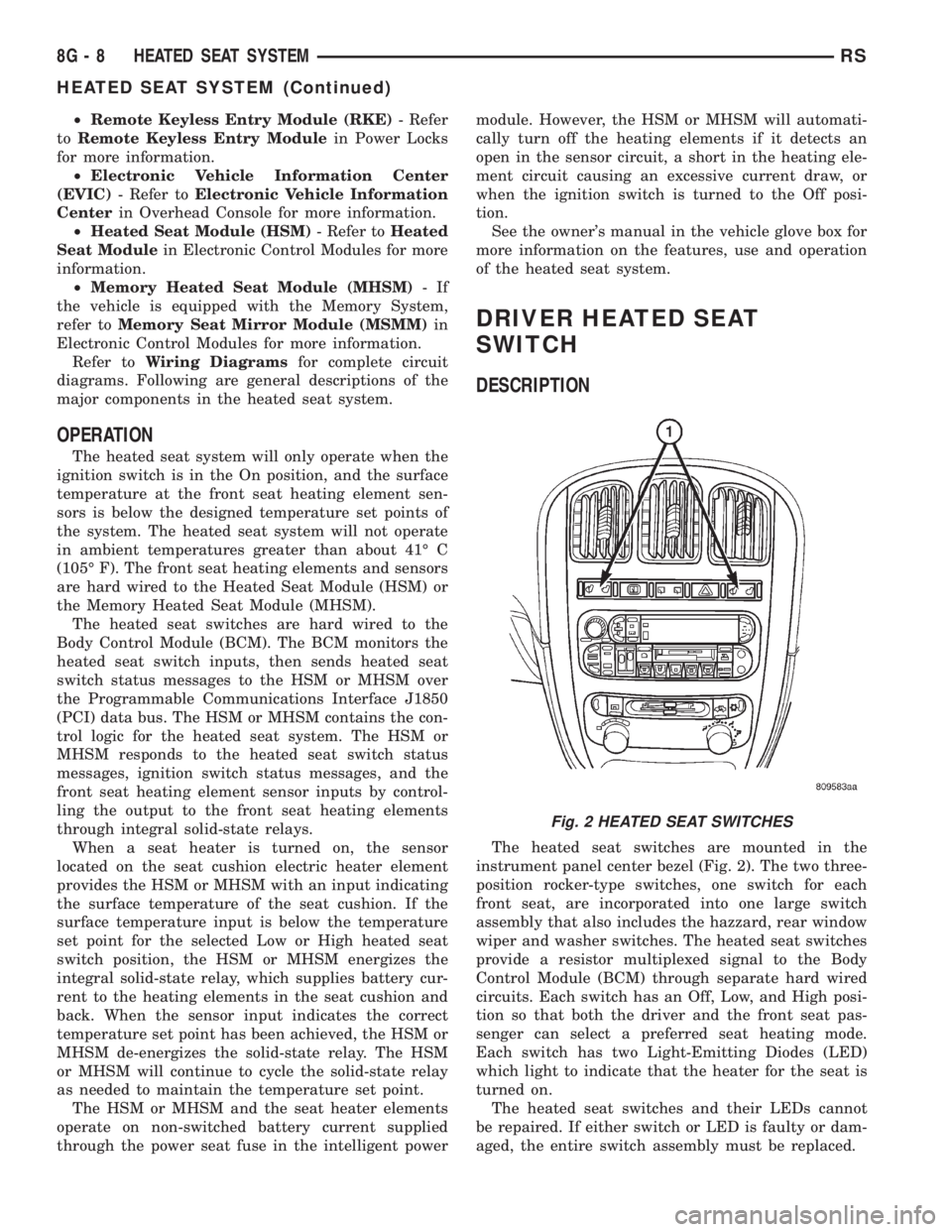
The heated seat switches are mounted in the
instrument panel center bezel (Fig. 2). The two three-
position rocker-type switches, one switch for each
front seat, are incorporated into one large switch
assembly that also includes the hazzard, rear window
wiper and washer switches. The heated seat switches
provide a resistor multiplexed signal to the Body
Control Module (BCM) through separate hard wired
circuits. Each switch has an Off, Low, and High posi-
tion so that both the driver and the front seat pas-
senger can select a preferred seat heating mode.
Each switch has two Light-Emitting Diodes (LED)
which light to indicate that the heater for the seat is
turned on.
The heated seat switches and their LEDs cannot
be repaired. If either switch or LED is faulty or dam-
aged, the entire switch assembly must be replaced.
Fig. 2 HEATED SEAT SWITCHES
8G - 8 HEATED SEAT SYSTEMRS
HEATED SEAT SYSTEM (Continued)
Page 1976 of 4284
STANDARD PROCEDURE - ELECTRONIC
VEHICLE INFORMATION CENTER
PROGRAMMING
EVIC PROGRAMMING MODE
Some vehicles are equipped with a Electronic Vehi-
cle Information Center (EVIC) equipped overhead
console. The Electronic Vehicle Information Center
(EVIC) provides the vehicle operator with a user
interface, which allows the selection of several
optional customer programmable electronic features
to suit individual preferences. The EVIC must be
placed into its programming mode in order to view or
change the programmable features. To enter the
EVIC programming mode and to view or change the
selected programmable features options, proceed as
follows:
(1) Turn the ignition switch to the On position.
(2) Depress and release the Menu push button.
The first item in the programmable features menu
list will appear in the EVIC display.
(3) Momentarily depress and release the Menu
push button to step through the programmable fea-
tures list. Each programmable feature and its cur-
rently selected option will appear on the EVIC
display in the sequence shown in the Programmable
Features list that follows.
(4) Momentarily depress and release the Step push
button to step through the available options for the
programmable feature being displayed.
(5) The option that last appears in the display
with a programmable feature before exiting the pro-
gramming mode, becomes the newly selected pro-
grammable feature option.
(6) The EVIC exits the programming mode and
returns to its normal operating mode when the C/T
push button is depressed or when the end of the pro-
grammable features menu list is reached, whichever
occurs first.
PROGRAMMABLE FEATURES
²LANGUAGE?- The options include English,
Francaise, Deutsch, Italiana, or Espanol. The default
is English. All EVIC display nomenclature, including
the trip computer functions, warning messages and
the programmable features appear in the selected
language.
²DISPLAY U.S. OR METRIC?- The options
include U.S. and M. The default is U.S. This feature
toggles the trip computer temperature, fuel economy
and odometer display readings between U.S. and
metric units of measure. It also changes the odome-
ter display in the instrument cluster.
²SERVICE INTV. =- The options include from
1000 to 12000 kilometers in 1000 kilometer incre-
ments (2000 to 7500 miles in 500 mile increments).The default is 12000 kilometers (7500 miles). The
selected distance becomes the interval at which the
Perform Service warning message will be displayed
by the EVIC. If a new distance is selected, a second
programmable feature appears,RESET SERVICE
DISTANCE?- The options include No and Yes. The
default is Yes. When Yes is selected, the accumulated
distance since the last previous Perform Service
warning message will be reset to zero because the
service interval has been changed. When No is
selected, the distance until the next Perform Service
warning message is reduced by the accumulated dis-
tance since the last previous message.
²USE FACTORY SETTINGS?- The options
include Yes and No. The default is Yes. When yes is
selected all the programmable features will return to
there defaults and the rest of the programmable fea-
tures will not be displayed. If No is selected the rest
of the programmable features will be displayed at
there default values. This feature will automatically
return to the Yes default under two conditions. First,
if no programmable features are changed from there
defaults. Second, if all the programmable features
equal there defaults.
²AUTO DOOR LOCKS?- The options include
Yes and No. The default is Yes. When Yes is selected,
all doors and the liftgate lock automatically when
vehicle speed reaches 25 kilometers-per-hour (15
miles-per-hour). If YES is selected, a second program-
mable feature appears,AUTO UNLOCK ON EXIT?
- The options again include Yes and No. The default
is No. When Yes is selected, following each Auto Door
Lock event all doors and the liftgate will automati-
cally unlock when the driver door is opened, if the
vehicle is stopped and the transmission gear selector
is in Park or Neutral. The Auto Door Unlock event
will only occur once following each Auto Door Lock
event.
²REMOTE UNLOCK- The options include
Driver Door 1st and All Doors. The default is Driver
Door 1st. When Diver Door 1st is selected, only the
driver door unlocks when the Unlock button of the
Remote Keyless Entry (RKE) transmitter is
depressed once. The Unlock button of the RKE trans-
mitter must be depressed twice to unlock all doors.
When All Doors is selected, all doors unlock when the
Unlock button of the RKE transmitter is depressed
once.
²REMOTE LINKED TO MEMORY?- This pro-
grammable feature only applies to vehicles equipped
with the optional memory / heated system. The
options include Yes and No. The default is No. When
Yes is selected, the memory system will recall the
Driver 1 or Driver 2 memory settings assigned to the
RKE transmitter being used to unlock the vehicle.
When No is selected, the memory system will only
8M - 8 OVERHEAD CONSOLERS
ELECTRONIC VEHICLE INFO CENTER (Continued)