2001 CHRYSLER VOYAGER ECO mode
[x] Cancel search: ECO modePage 3729 of 4284
through the rear evaporator when the rear air condi-
tioner is turned Off.
DIAGNOSIS AND TESTING - EXPANSION VALVE
WARNING: REFER TO THE APPLICABLE WARN-
INGS AND CAUTIONS FOR THIS SYSTEM BEFORE
PERFORMING THE FOLLOWING OPERATION.
(Refer to 24 - HEATING & AIR CONDITIONING/
PLUMBING - FRONT - WARNING - A/C PLUMBING)
and (Refer to 24 - HEATING & AIR CONDITIONING/
PLUMBING - FRONT - CAUTION - A/C PLUMBING).
NOTE: The expansion valve should only be tested
following testing of the compressor.
NOTE: Liquid CO
2is required to test the expansion
valve. This material is available from most welding
supply facilities. Liquid CO
2is also available from
companies which service and sell fire extinguish-
ers.
When testing the expansion valve, the work area
and the vehicle temperature must be 21É to 27É C
(70É to 85É F). To test the expansion valve:
(1) Connect a charging station or manifold gauge
set to the refrigerant system service ports. Verify the
refrigerant charge level.
(2) Close all doors, windows and vents to the pas-
senger compartment.
(3) Set the heater-air conditioner controls so that
the compressor is operating, the temperature control
is in the highest temperature position, the mode door
is directing the output to the floor outlets, and the
blower is operating at the highest speed setting.
(4) Start the engine and allow it to idle at 1000
rpm. After the engine has reached normal operating
temperature, allow the passenger compartment to
heat up. This will create the need for maximum
refrigerant flow into the evaporator.
(5) If the refrigerant charge is sufficient, the dis-
charge (high pressure) gauge should read 965 to 1655
kPa (140 to 240 psi). The suction (low pressure)
gauge should read 140 kPa to 207 kPa (20 psi to 30
psi). If OK, go to Step 6. If not OK, replace the faulty
expansion valve.
WARNING:
PROTECT THE SKIN AND EYES FROM EXPOSURE
TO LIQUID CO
2. PERSONAL INJURY CAN RESULT.
(6) If the suction (low pressure) gauge reads
within the specified range, freeze the expansion valve
control head for 30 seconds using liquid CO
2or
another suitable super-cold material.Do not spray
R-134a or R-12 refrigerant on the expansionvalve control head for this test.The suction (low
pressure) gauge reading should drop by 10 psi. If OK,
go to Step 7 If not OK, replace the faulty expansion
valve.
(7) Allow the expansion valve control head to thaw.
The suction (low pressure) gauge reading should sta-
bilize at 140 kPa to 240 kPa (20 psi to 30 psi). If not
OK, replace the faulty expansion valve.
(8) When expansion valve testing is complete, test
the overall air conditioner performance. (Refer to 24 -
HEATING & AIR CONDITIONING - DIAGNOSIS
AND TESTING - A/C PERFORMANCE TEST).
Remove all test equipment before returning the vehi-
cle to service.
REMOVAL
WARNING: REFER TO THE APPLICABLE WARN-
INGS AND CAUTIONS FOR THIS SYSTEM BEFORE
PERFORMING THE FOLLOWING OPERATION.
(Refer to 24 - HEATING & AIR CONDITIONING/
PLUMBING - FRONT - WARNING - A/C PLUMBING),
(Refer to 24 - HEATING & AIR CONDITIONING/
PLUMBING - FRONT - CAUTION - A/C PLUMBING),
and (Refer to 24 - HEATING & AIR CONDITIONING/
PLUMBING - FRONT - WARNING - HEATER PLUMB-
ING).
(1) Remove the rear heater-A/C unit housing from
the vehicle. (Refer to 24 - HEATING & AIR CONDI-
TIONING/DISTRIBUTION - REAR/REAR HEATER-
A/C HOUSING - REMOVAL).
(2) Carefully remove the foam insulator wrap from
the rear expansion valve.
(3) Remove the rear evaporator line extension from
the expansion valve. (Refer to 24 - HEATING & AIR
CONDITIONING/PLUMBING - REAR/EVAPORA-
TOR - REMOVAL - EVAPORATOR LINE EXTEN-
SION).
(4) If the vehicle is equipped with the optional
Automatic Temperature Control (ATC) system, dis-
connect the expansion valve solenoid pigtail wire con-
nector from the rear HVAC wire harness connector
(Fig. 4).
(5) Remove the two screws that secure the expan-
sion valve to the evaporator tube sealing plate.
(6) Remove the expansion valve from the evapora-
tor tubes.
(7) Remove the seals from the evaporator tube fit-
tings and discard.
(8) Install plugs in, or tape over the opened evap-
orator tube fittings and both expansion valve ports.
INSTALLATION
(1) Remove the tape or plugs from the evaporator
tube fittings and both expansion valve ports.
RSPLUMBING - REAR24-99
EXPANSION VALVE (Continued)
Page 3733 of 4284
CAUTION:
When removing hoses from outlet nipples, do not
use excessive force. Outlet nipples may become
damaged and leak engine coolant.
(4) Compress insert in rear heater hose quick con-
nection and pull downward on hose. (Fig. 12)
(5) Remove (3) straps securing underbody lines.
(Fig. 9)
(6) Separate and remove rear heater lines from
vehicle.
INSTALLATION
There are several heater core plumbing configura-
tions used on this model, depending upon the engine
size and other optional equipment. One plumbing
configuration is used for all 2.4L engines (Fig. 21),
while the 3.3L and 3.8L engines have unique heater
return plumbing on the engine for models with or
without an optional engine oil cooler (Fig. 24) or (Fig.
25). There are also unique plumbing configurations
at the heater core for models with or without the
optional rear heater and air conditioner (Fig. 22) or
(Fig. 23). All models use a combination of formed
steel tubing and rubber hoses. In most cases, the
rubber hose is secured to the steel tubing with a
spring tension clamp.
WARNING: REFER TO THE APPLICABLE WARN-
INGS AND CAUTIONS FOR THIS SYSTEM BEFORE
PERFORMING THE FOLLOWING OPERATION.
(Refer to 24 - HEATING & AIR CONDITIONING/
PLUMBING FRONT - WARNING - HEATER PLUMB-
ING).
(1) Using spring tension clamp pliers, compress
and slide the clamps that secure each end of the
heater hose toward the center of the hose being
installed. Release the clamp when it is near the cen-
ter of the hose.
(2) Grasp one end of the heater hose being
installed firmly and carefully twist the hose back and
forth while pushing it over from the barbed end of
the nipple. Repeat this procedure at the opposite end
of the hose being installed.
(3) Using spring tension clamp pliers, compress
and slide the clamps that secure each end of the
heater hose over the tube or nipple. Release the
clamp when it is over the tube or nipple.
(4) Refill the engine cooling system. (Refer to 7 -
COOLING - STANDARD PROCEDURE - COOLING
SYSTEM REFILL).
SUCTION LINE
REMOVAL
The front air conditioner suction line includes the
low side service port on a section of tubing located
near the compressor. On models equipped with the
optional rear air conditioner, the front air conditioner
suction line also includes a suction line hose and
tube extension that connects the front suction line to
the suction line for the rear air conditioner.
WARNING: REFER TO THE APPLICABLE WARN-
INGS AND CAUTIONS FOR THIS SYSTEM BEFORE
PERFORMING THE FOLLOWING OPERATION.
(Refer to 24 - HEATING & AIR CONDITIONING/
PLUMBING - FRONT - WARNING - A/C PLUMBING)
and (Refer to 24 - HEATING & AIR CONDITIONING/
PLUMBING - FRONT - CAUTION - A/C PLUMBING).
(1) Recover the refrigerant from the refrigerant
system. (Refer to 24 - HEATING & AIR CONDI-
TIONING/PLUMBING - FRONT/REFRIGERANT -
STANDARD PROCEDURE - REFRIGERANT
RECOVERY).
(2) Disconnect and isolate the battery negative
cable.
(3) Remove the air cleaner top cover and snorkel
from the air cleaner housing located on the right side
of the engine compartment.
(4) Disconnect the drain tube from the wiper mod-
ule drain on the right side of the engine compart-
ment.
(5) Remove the nut that secures the suction line
fitting to the top of the compressor.
(6) Disconnect the suction line fitting from the
compressor suction port.
(7) Remove the seal from the suction line fitting
and discard.
(8) Install plugs in, or tape over the opened suc-
tion line fitting and the compressor suction port.
(9) Disengage the retainer that secures the suction
line routing clip to the filter-drier mounting bracket
on the side of the right front strut tower in the
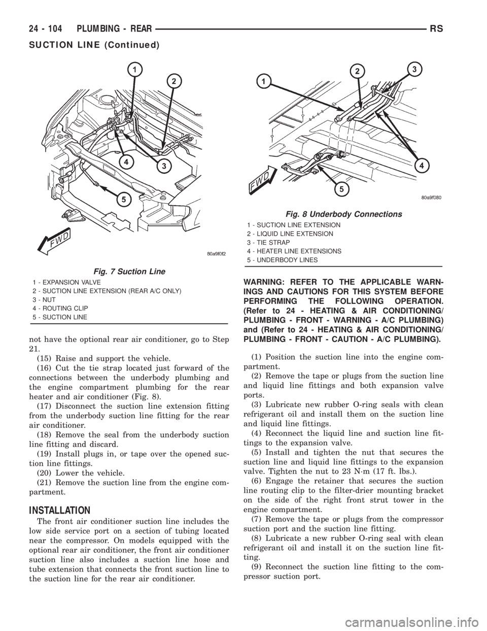
engine compartment (Fig. 7).
(10) Remove the nut that secures the suction line
and liquid line fittings to the expansion valve.
(11) Disconnect the suction line and liquid line fit-
tings from the expansion valve.
(12) Remove the seals from the suction line and
liquid line fittings and discard.
(13) Install plugs in, or tape over the opened suc-
tion line and liquid line fittings and both expansion
valve ports.
(14) If the vehicle is equipped with the optional
rear air conditioner, go to Step 15. If the vehicle does
RSPLUMBING - REAR24 - 103
HEATER HOSE (Continued)
Page 3734 of 4284
not have the optional rear air conditioner, go to Step
21.
(15) Raise and support the vehicle.
(16) Cut the tie strap located just forward of the
connections between the underbody plumbing and
the engine compartment plumbing for the rear
heater and air conditioner (Fig. 8).
(17) Disconnect the suction line extension fitting
from the underbody suction line fitting for the rear
air conditioner.
(18) Remove the seal from the underbody suction
line fitting and discard.
(19) Install plugs in, or tape over the opened suc-
tion line fittings.
(20) Lower the vehicle.
(21) Remove the suction line from the engine com-
partment.
INSTALLATION
The front air conditioner suction line includes the
low side service port on a section of tubing located
near the compressor. On models equipped with the
optional rear air conditioner, the front air conditioner
suction line also includes a suction line hose and
tube extension that connects the front suction line to
the suction line for the rear air conditioner.WARNING: REFER TO THE APPLICABLE WARN-
INGS AND CAUTIONS FOR THIS SYSTEM BEFORE
PERFORMING THE FOLLOWING OPERATION.
(Refer to 24 - HEATING & AIR CONDITIONING/
PLUMBING - FRONT - WARNING - A/C PLUMBING)
and (Refer to 24 - HEATING & AIR CONDITIONING/
PLUMBING - FRONT - CAUTION - A/C PLUMBING).
(1) Position the suction line into the engine com-
partment.
(2) Remove the tape or plugs from the suction line
and liquid line fittings and both expansion valve
ports.
(3) Lubricate new rubber O-ring seals with clean
refrigerant oil and install them on the suction line
and liquid line fittings.
(4) Reconnect the liquid line and suction line fit-
tings to the expansion valve.
(5) Install and tighten the nut that secures the
suction line and liquid line fittings to the expansion
valve. Tighten the nut to 23 N´m (17 ft. lbs.).
(6) Engage the retainer that secures the suction
line routing clip to the filter-drier mounting bracket
on the side of the right front strut tower in the
engine compartment.
(7) Remove the tape or plugs from the compressor
suction port and the suction line fitting.
(8) Lubricate a new rubber O-ring seal with clean
refrigerant oil and install it on the suction line fit-
ting.
(9) Reconnect the suction line fitting to the com-
pressor suction port.
Fig. 7 Suction Line
1 - EXPANSION VALVE
2 - SUCTION LINE EXTENSION (REAR A/C ONLY)
3 - NUT
4 - ROUTING CLIP
5 - SUCTION LINE
Fig. 8 Underbody Connections
1 - SUCTION LINE EXTENSION
2 - LIQUID LINE EXTENSION
3 - TIE STRAP
4 - HEATER LINE EXTENSIONS
5 - UNDERBODY LINES
24 - 104 PLUMBING - REARRS
SUCTION LINE (Continued)
Page 3735 of 4284
(10) Install and tighten the nut that secures the
suction line fitting to the compressor. Tighten the nut
to 23 N´m (17 ft. lbs.).
(11) Reconnect the drain tube to the wiper module
drain on the right side of the engine compartment.
(12) Reinstall the air cleaner top cover and snorkel
onto the air cleaner housing located on the right side
of the engine compartment.
(13) Reconnect the battery negative cable.
(14) If the vehicle is equipped with the optional
rear air conditioner, go to Step 15. If the vehicle does
not have the optional rear air conditioner, go to Step
21.
(15) Raise and support the vehicle.
(16) Remove the tape or plugs from the suction
line extension fitting and the underbody suction line
fitting (Fig. 35).
(17) Lubricate a new rubber O-ring seal with clean
refrigerant oil and install it on the underbody suction
line fitting.
(18) Reconnect the suction line extension fitting to
the underbody suction line fitting. Tighten the fit-
tings to 23 N´m (17 ft. lbs.).
(19) Install a new tie strap just forward of the con-
nections between the underbody plumbing and the
engine compartment plumbing for the rear heater
and air conditioner.
(20) Lower the vehicle.
(21) Evacuate the refrigerant system. (Refer to 24
- HEATING & AIR CONDITIONING/PLUMBING -
FRONT/REFRIGERANT - STANDARD PROCE-
DURE - REFRIGERANT SYSTEM EVACUATE).
(22) Charge the refrigerant system. (Refer to 24 -
HEATING & AIR CONDITIONING/PLUMBING -
FRONT/REFRIGERANT - STANDARD PROCE-
DURE - REFRIGERANT SYSTEM CHARGE).UNDERBODY LINES
DESCRIPTION
The rear heater-A/C unit plumbing is used only on
models with the optional rear heater-A/C unit. The
formed metal rear heater-A/C unit suction line, liquid
line, and heater lines are available for separate ser-
vice replacement. The molded and straight heater
hoses used on the rear heater-A/C unit can be ser-
viced in the vehicle. Refer to Group 7 - Cooling Sys-
tem for the heater hose service procedures.
OPERATION
The rear heater and A/C lines are all serviced as
individual pieces. When disconnecting any line or
block ensure that the area around it is clean of any
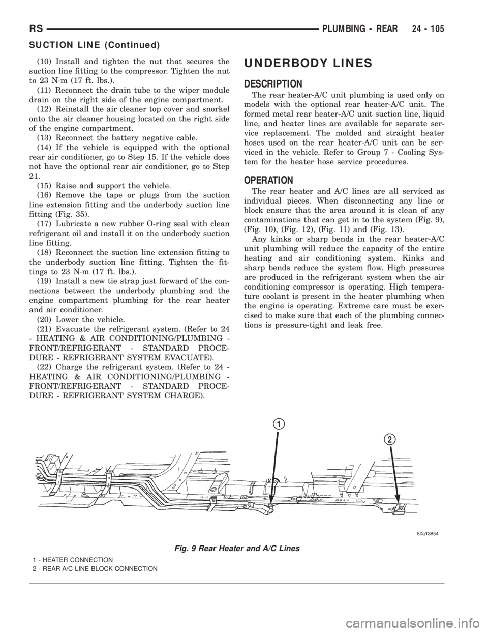
contaminations that can get in to the system (Fig. 9),
(Fig. 10), (Fig. 12), (Fig. 11) and (Fig. 13).
Any kinks or sharp bends in the rear heater-A/C
unit plumbing will reduce the capacity of the entire
heating and air conditioning system. Kinks and
sharp bends reduce the system flow. High pressures
are produced in the refrigerant system when the air
conditioning compressor is operating. High tempera-
ture coolant is present in the heater plumbing when
the engine is operating. Extreme care must be exer-
cised to make sure that each of the plumbing connec-
tions is pressure-tight and leak free.
Fig. 9 Rear Heater and A/C Lines
1 - HEATER CONNECTION
2 - REAR A/C LINE BLOCK CONNECTION
RSPLUMBING - REAR24 - 105
SUCTION LINE (Continued)
Page 3742 of 4284
REFRIGERANT
DIAGNOSIS AND TESTING - REFRIGERANT
SYSTEM CHARGE LEVEL 2.5L DIESEL
WARNING: REFER TO THE APPLICABLE WARN-
INGS AND CAUTIONS FOR THIS SYSTEM BEFORE
PERFORMING THE FOLLOWING OPERATION.
(Refer to 24 - HEATING & AIR CONDITIONING/
PLUMBING - FRONT - WARNING - A/C PLUMBING)
and (Refer to 24 - HEATING & AIR CONDITIONING/
PLUMBING - FRONT - CAUTION - A/C PLUMBING).
NOTE: The proper amount of R-134a refrigerant for
the refrigerant system in this model is:
²Single or Dual Zone (Front Unit Only - 2.5L Die-
sel) ± 0.91 kilograms (2.00 pounds or 32 ounces)
²Single or Dual Zone (Front Unit Only) - 0.96
kilograms (2.13 pounds or 34 ounces)
²Three Zone (Front and Rear Units) - 1.31 kilo-
grams (2.88 pounds or 46 ounces)
The procedure that follows should be used to deter-
mine whether the refrigerant system contains the
proper refrigerant charge. Symptoms of an improper
refrigerant charge (low) include: poor air conditionerperformance, fog emitted from the air conditioner out-
lets, a hissing sound from the expansion valve/evapo-
rator area. There are two different methods with
which the refrigerant charge level may be tested:
²Using a DRBIIItscan tool, a thermocouple and
the Charge Determination Chart (Fig. 3). Refer to
the appropriate diagnostic information.
²Using a manifold gauge set, a thermocouple and
the Charge Determination Chart (Fig. 3).
A temperature probe is required to measure liquid
line temperature. The clamp-on, Type K thermocou-
ple temperature probe used in this procedure is
available through the DaimlerChrysler Professional
Service Equipment (PSE) program. This probe (PSE
#66-324-0014 or #80PK-1A) is compatible with tem-
perature-measuring instruments that accept Type K
thermocouples, and have a miniature connector
input. Other temperature probes are available
through aftermarket sources; however, all references
in this procedure will reflect the use of the probe
made available through the PSE program.
In order to use the temperature probe, a digital ther-
mometer will also be required. If a digital thermometer
is not available, an adapter is available through the
PSE program that will convert any standard digital
multimeter into a digital thermometer. This adapter is
designed to accept any standard Type K thermocouple.
If a digital multimeter is not available, this tool is also
available through the PSE program.
NOTE: When connecting the service equipment
couplings to the refrigerant system service ports,
be certain that the valve of each coupling is fully
closed. This will reduce the amount of effort
required to make the connection.
(1) Remove the caps from the refrigerant system
service ports and attach a manifold gauge set or a
R-134a refrigerant recovery/recycling/charging sta-
tion that meets SAE Standard J2210 to the refriger-
ant system.
(2) Attach a clamp-on thermocouple to the liquid
line. The thermocouple must be placed as close to the
A/C pressure transducer as possible to accurately
observe liquid line temperature.
(3) Bring the refrigerant system up to operating
temperature and pressure. This is done by allowing
the engine to run at idle under the following condi-
tions for five minutes.
(a) Front windows are open.
(b) Transaxle in Park.
(c) Front heater-A/C controls set to outside air,
full cool, panel mode, blower high, and compressor
engaged.
(d)
If the vehicle is so equipped, the rear heater-
A/C controls must be set to full cool and blower high.
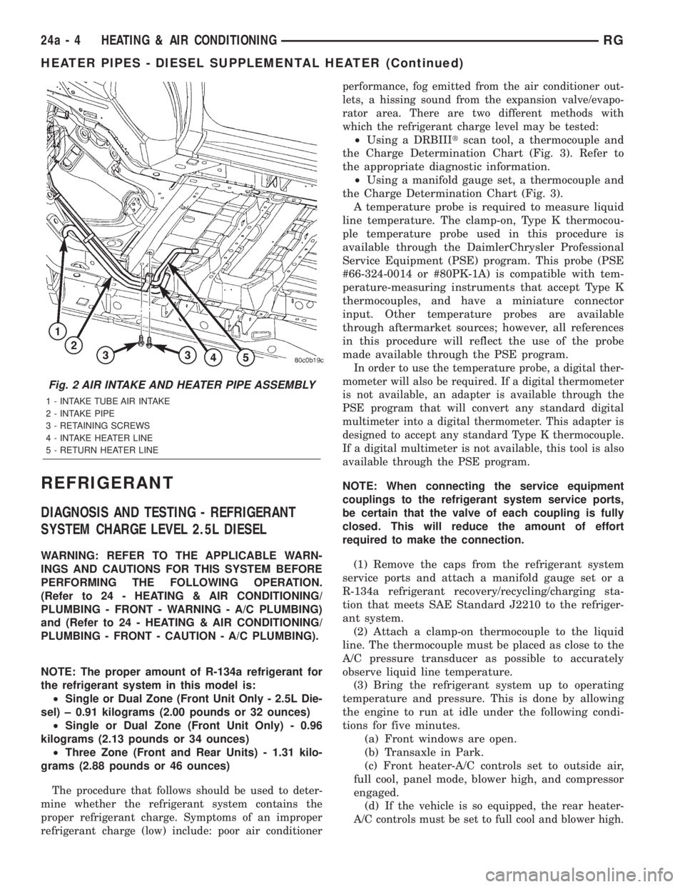
Fig. 2 AIR INTAKE AND HEATER PIPE ASSEMBLY
1 - INTAKE TUBE AIR INTAKE
2 - INTAKE PIPE
3 - RETAINING SCREWS
4 - INTAKE HEATER LINE
5 - RETURN HEATER LINE
24a - 4 HEATING & AIR CONDITIONINGRG
HEATER PIPES - DIESEL SUPPLEMENTAL HEATER (Continued)
Page 3755 of 4284
²Ethanel content learn is takeng place and the
ethenal used once flag is set
SuspendÐThe Task Manager does not mature a
catalyst fault if any of the following are present:
²Oxygen Sensor Monitor, Priority 1
²Upstream Oxygen Sensor Heater, Priority 1
²EGR Monitor, Priority 1
²EVAP Monitor, Priority 1
²Fuel System Monitor, Priority 2
²Misfire Monitor, Priority 2
DESCRIPTION - VEHICLE EMISSION CONTROL
INFORMATION LABEL
All models have a Vehicle Emission Control Infor-
mation (VECI) Label. Chrysler permanently attaches
the label in the engine compartment. It cannot be
removed without defacing information and destroying
the label.
The label contains the vehicle's emission specifica-
tions and vacuum hose routings. All hoses must be
connected and routed according to the label.
DESCRIPTION - TRIP DEFINITION
A ªTripº means vehicle operation (following an
engine-off period) of duration and driving mode such
that all components and systems are monitored at
least once by the diagnostic system. The monitors
must successfully pass before the PCM can verify
that a previously malfunctioning component is meet-
ing the normal operating conditions of that compo-
nent. For misfire or fuel system malfunction, the
MIL may be extinguished if the fault does not recur
when monitored during three subsequent sequential
driving cycles in which conditions are similar to
those under which the malfunction was first deter-
mined.
Anytime the MIL is illuminated, a DTC is stored.
The DTC can self erase only when the MIL has been
extinguished. Once the MIL is extinguished, the
PCM must pass the diagnostic test for the most
recent DTC for 40 warm-up cycles (80 warm-up
cycles for the Fuel System Monitor and the Misfire
Monitor) . A warm-up cycle can best be described by
the following:
²The engine must be running
²A rise of 40ÉF in engine temperature must occur
from the time when the engine was started
²Engine coolant temperature must reach at least
160ÉF
²A ªdriving cycleº that consists of engine start up
and engine shut off.
Once the above conditions occur, the PCM is con-
sidered to have passed a warm-up cycle. Due to the
conditions required to extinguish the MIL and erase
the DTC, it is most important that after a repair hasbeen made, all DTC's be erased and the repair veri-
fied.
OPERATION - NON-MONITORED CIRCUITS
The PCM does not monitor all circuits, systems
and conditions that could have malfunctions causing
driveability problems. However, problems with these
systems may cause the PCM to store diagnostic trou-
ble codes for other systems or components. For exam-
ple, a fuel pressure problem will not register a fault
directly, but could cause a rich/lean condition or mis-
fire. This could cause the PCM to store an oxygen
sensor or misfire diagnostic trouble code.
The major non-monitored circuits are listed below
along with examples of failures modes that do not
directly cause the PCM to set a DTC, but for a sys-
tem that is monitored.
FUEL PRESSURE
The fuel pressure regulator controls fuel system
pressure. The PCM cannot detect a clogged fuel
pump inlet filter, clogged in-line fuel filter, or a
pinched fuel supply or return line. However, these
could result in a rich or lean condition causing the
PCM to store an oxygen sensor or fuel system diag-
nostic trouble code.
SECONDARY IGNITION CIRCUIT
The PCM cannot detect an inoperative ignition coil,
fouled or worn spark plugs, ignition cross firing, or
open spark plug cables.
CYLINDER COMPRESSION
The PCM cannot detect uneven, low, or high engine
cylinder compression.
EXHAUST SYSTEM
The PCM cannot detect a plugged, restricted or
leaking exhaust system. It may set a EGR or Fuel
system fault or O2S.
FUEL INJECTOR MECHANICAL MALFUNCTIONS
The PCM cannot determine if a fuel injector is
clogged, the needle is sticking or if the wrong injector
is installed. However, these could result in a rich or
lean condition causing the PCM to store a diagnostic
trouble code for either misfire, an oxygen sensor, or
the fuel system.
EXCESSIVE OIL CONSUMPTION
Although the PCM monitors engine exhaust oxygen
content when the system is in closed loop, it cannot
determine excessive oil consumption.
THROTTLE BODY AIR FLOW
The PCM cannot detect a clogged or restricted air
cleaner inlet or filter element.
RSEMISSIONS CONTROL25-5
EMISSIONS CONTROL (Continued)
Page 3759 of 4284
speed above the maximum threshold (2000 rpm), the
PCM will not store a DTC.
There are several operating conditions for which
the PCM monitors and sets DTC's. Refer to Moni-
tored Systems, Components, and Non-Monitored Cir-
cuits in this section.
NOTE: Various diagnostic procedures may actually
cause a diagnostic monitor to set a DTC. For
instance, pulling a spark plug wire to perform a
spark test may set the misfire code. When a repair
is completed and verified, use the DRBIIITscan tool
to erase all DTC's and extinguish the MIL.
Technicians can display stored DTC's. Refer to
Diagnostic Trouble Codes in this section. For DTC
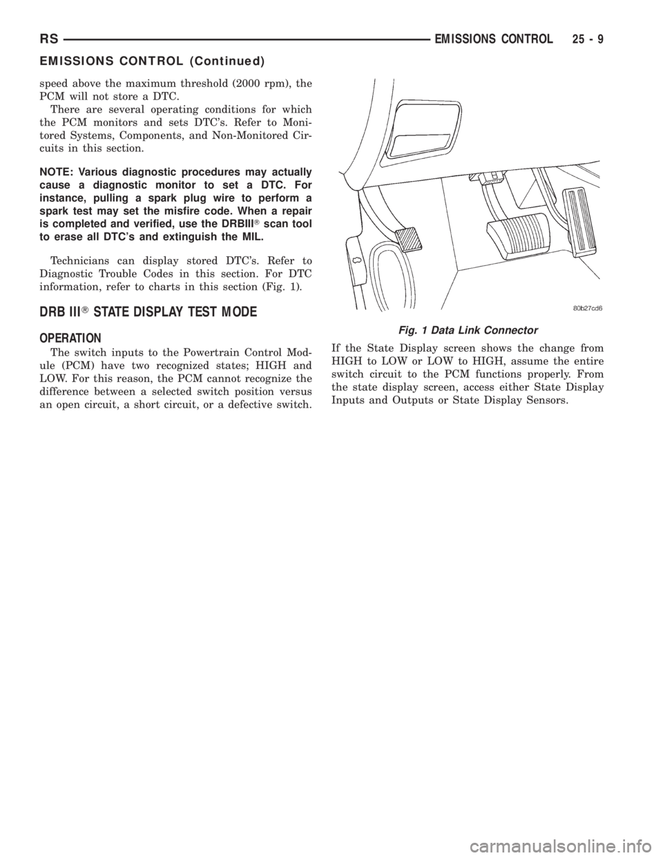
information, refer to charts in this section (Fig. 1).
DRB IIITSTATE DISPLAY TEST MODE
OPERATION
The switch inputs to the Powertrain Control Mod-
ule (PCM) have two recognized states; HIGH and
LOW. For this reason, the PCM cannot recognize the
difference between a selected switch position versus
an open circuit, a short circuit, or a defective switch.If the State Display screen shows the change from
HIGH to LOW or LOW to HIGH, assume the entire
switch circuit to the PCM functions properly. From
the state display screen, access either State Display
Inputs and Outputs or State Display Sensors.
Fig. 1 Data Link Connector
RSEMISSIONS CONTROL25-9
EMISSIONS CONTROL (Continued)
Page 3763 of 4284
LEAK DETECTION PUMP
DESCRIPTION
The leak detection pump is a device used to detect
a leak in the evaporative system.
The primary components within the leak detection
pump assembly are: a three-port leak detection sole-
noid valve, a pump assembly that includes a spring
loaded diaphragm, a reed switch which is used to
monitor the pump diaphragm movement (position),
two check valves, and a spring loaded vent seal
valve.
OPERATION - LDP
Immediately after a cold start, when the engine
temperature is between 40ÉF and 86ÉF, the 3 port
solenoid is briefly energized. This initializes the
pump by drawing air into the pump cavity and also
closes the vent seal. During non-test test conditions,
the vent seal is held open by the pump diaphragm
assembly which pushes it open at the full travel posi-
tion. The vent seal will remain closed while the
pump is cycling. This is due to the operation of the 3
port solenoid which prevents the diaphragm assem-
bly from reaching full travel. After the brief initial-
ization period, the solenoid is de-energized, allowing
atmospheric pressure to enter the pump cavity. This
permits the spring to drive the diaphragm which
forces air out of the pump cavity and into the vent
system. When the solenoid is energized and de-ener-
gized, the cycle is repeated creating flow in typical
diaphragm pump fashion. The pump is controlled in
2 modes:
PUMP MODE:The pump is cycled at a fixed rate
to achieve a rapid pressure build in order to shorten
the overall test time.
TEST MODE:The solenoid is energized with a
fixed duration pulse. Subsequent fixed pulses occur
when the diaphragm reaches the switch closure
point.
The spring in the pump is set so that the system
will achieve an equalized pressure of about 7.5 inches
of water.
When the pump starts, the cycle rate is quite high.
As the system becomes pressurized, pump rate drops.
If there is no leak, the pump will quit. If there is a
leak, the test is terminated at the end of the test
mode.
If there is no leak, the purge monitor is run. If the
cycle rate increases due to the flow through the
purge system, the test is passed and the diagnostic is
complete.
The canister vent valve will unseal the system
after completion of the test sequence as the pump
diaphragm assembly moves to the full travel position.
OPERATION - LDP SWITCH
The leak detection pump LDP assembly incorpo-
rates two primary functions: it detects a leak in the
evaporative system, and it seals the evaporative sys-
tem so that the required leak detection monitor test
can be run.
The three-port LDP solenoid valve is used to
expose either engine vacuum or atmospheric pressure
to the top side of the leak detection pump diaphragm.
When the LDP solenoid valve is denergized its port
(opening) to engine vacuum is blocked off. This
allows ambient air (atmospheric pressure) to enter
the top of the pump diaphragm. The spring load on
the diaphragm will push the diaphragm down, as
long as there is no pressure present in the rest of the
evaporative system. If there is sufficient evaporative
system pressure present, then the pump diaphragm
will stay in the9up9position. If the evaporative sys-
tem pressure decays, then the pump diaphragm will
eventually fall. The rate of this decent is dependent
upon the size of the evaporative system leak (Large
or small).
When the LDP solenoid valve is energized the port
(opening) to atmosphere is blocked off. At the same
time, the port to engine vacuum is opened. Engine
vacuum replaces atmospheric pressure. When engine
vacuum is sufficient, it over comes the spring pres-
sure load on the pump diaphragm and causes the
diaphragm to rise to its9up9position. The reed
switch will change state depending upon the position
of the pump diaphragm.
If the diaphragm is in the9up9position the reed
switch will be in its9open9state. This means that the
12 volt signal sense to the PCM is interrupted. Zero
volts is detected by the PCM. If the pump diaphragm
is in the9down9position the reed switch will be in its
9closed9state. 12 volts is sent to the PCM via the
switch sense circuit.
The check valves are one-way valves. The first
check valve is used to draw outside air into the lower
chamber of the LDP (the space that is below the
pump diaphragm). The second check valve is used to
vent this outside air, which has become pressurized
from the fall of the pump diaphragm, into the evap-
orative system.
The spring loaded vent seal valve, inside the LDP
is used to seal off the evaporative system. When the
pump diaphragm is in the9up9position the spring
pushes the vent seal valve closed. The vent seal valve
opens only when the pump diaphragm is in its9full
down9position. When the pump assembly is in its
pump mode the pump diaphragm is not allowed to
descend (fall) so far as to allow the vent seal valve to
open. This allows the leak detection pump to develop
the required pressure within the evaporative system
for system leak testing.
RSEVAPORATIVE EMISSIONS25-13