2001 CHRYSLER VOYAGER Engine
[x] Cancel search: EnginePage 4235 of 4284
TEST ACTION APPLICABILITY
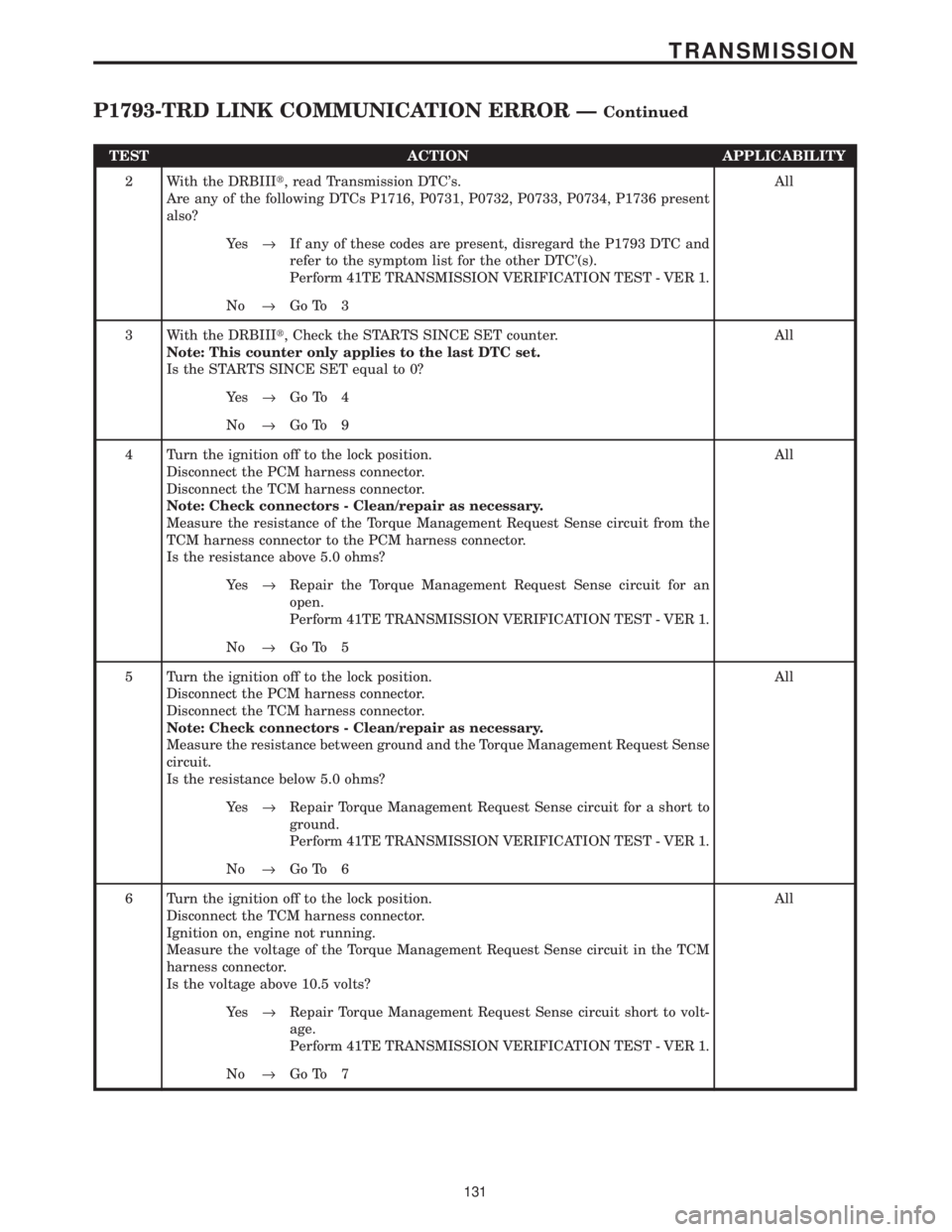
2 With the DRBIIIt, read Transmission DTC's.
Are any of the following DTCs P1716, P0731, P0732, P0733, P0734, P1736 present
also?All
Ye s®If any of these codes are present, disregard the P1793 DTC and
refer to the symptom list for the other DTC'(s).
Perform 41TE TRANSMISSION VERIFICATION TEST - VER 1.
No®Go To 3
3 With the DRBIIIt, Check the STARTS SINCE SET counter.
Note: This counter only applies to the last DTC set.
Is the STARTS SINCE SET equal to 0?All
Ye s®Go To 4
No®Go To 9
4 Turn the ignition off to the lock position.
Disconnect the PCM harness connector.
Disconnect the TCM harness connector.
Note: Check connectors - Clean/repair as necessary.
Measure the resistance of the Torque Management Request Sense circuit from the
TCM harness connector to the PCM harness connector.
Is the resistance above 5.0 ohms?All
Ye s®Repair the Torque Management Request Sense circuit for an
open.
Perform 41TE TRANSMISSION VERIFICATION TEST - VER 1.
No®Go To 5
5 Turn the ignition off to the lock position.
Disconnect the PCM harness connector.
Disconnect the TCM harness connector.
Note: Check connectors - Clean/repair as necessary.
Measure the resistance between ground and the Torque Management Request Sense
circuit.
Is the resistance below 5.0 ohms?All
Ye s®Repair Torque Management Request Sense circuit for a short to
ground.
Perform 41TE TRANSMISSION VERIFICATION TEST - VER 1.
No®Go To 6
6 Turn the ignition off to the lock position.
Disconnect the TCM harness connector.
Ignition on, engine not running.
Measure the voltage of the Torque Management Request Sense circuit in the TCM
harness connector.
Is the voltage above 10.5 volts?All
Ye s®Repair Torque Management Request Sense circuit short to volt-
age.
Perform 41TE TRANSMISSION VERIFICATION TEST - VER 1.
No®Go To 7
131
TRANSMISSION
P1793-TRD LINK COMMUNICATION ERROR ÐContinued
Page 4236 of 4284

TEST ACTION APPLICABILITY
7 Turn the ignition off to the lock position.
Disconnect the TCM harness connector.
Ignition on, engine not running.
Measure the voltage of the Torque Management Request Sense circuit in the TCM
harness connector.
Is the voltage above 7.0 volts?All
Ye s®Replace the TCM. WITH THE DRBIIItPERFORM QUICK
LEARN AND REPROGRAM PINION FACTOR.
Perform 41TE TRANSMISSION VERIFICATION TEST - VER 1.
No®Go To 8
8 If there are no possible causes remaining, view repair. All
Repair
Replace the Powertrain Control Module. Replace and program the
PCM Module in accordance with the Service Information.
Perform 41TE TRANSMISSION VERIFICATION TEST - VER 1.
9 The conditions necessary to set this DTC are not present at this time.
Using the schematics as a guide, inspect the wiring and connectors specific to this
circuit.
Wiggle the wiring while checking for shorts and open circuits.
Were there any problems found?All
Ye s®Repair as necessary.
Perform 41TE TRANSMISSION VERIFICATION TEST - VER 1.
No®Test Complete.
132
TRANSMISSION
P1793-TRD LINK COMMUNICATION ERROR ÐContinued
Page 4237 of 4284
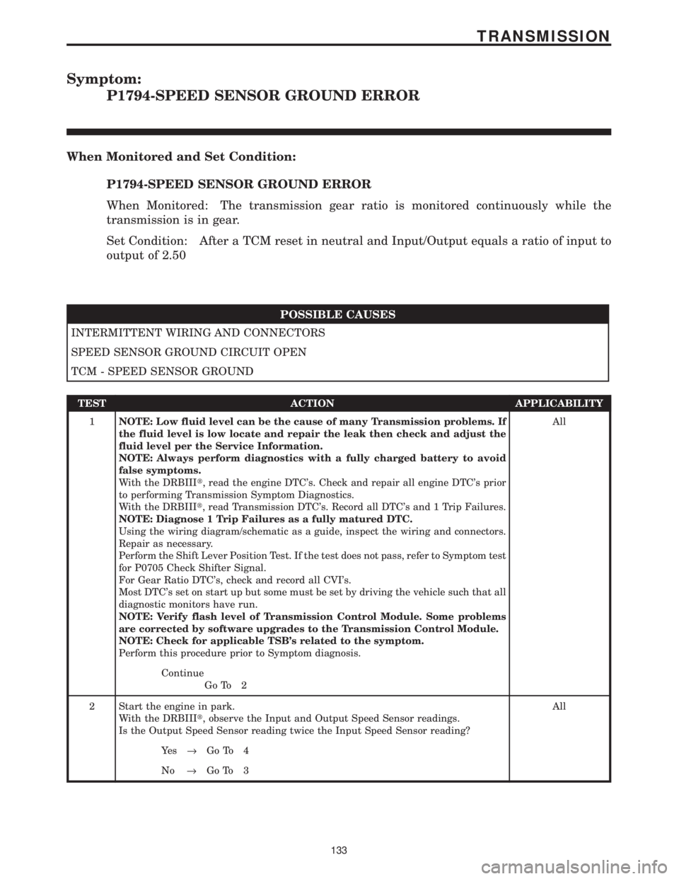
Symptom:
P1794-SPEED SENSOR GROUND ERROR
When Monitored and Set Condition:
P1794-SPEED SENSOR GROUND ERROR
When Monitored: The transmission gear ratio is monitored continuously while the
transmission is in gear.
Set Condition: After a TCM reset in neutral and Input/Output equals a ratio of input to
output of 2.50
POSSIBLE CAUSES
INTERMITTENT WIRING AND CONNECTORS
SPEED SENSOR GROUND CIRCUIT OPEN
TCM - SPEED SENSOR GROUND
TEST ACTION APPLICABILITY
1NOTE: Low fluid level can be the cause of many Transmission problems. If
the fluid level is low locate and repair the leak then check and adjust the
fluid level per the Service Information.
NOTE: Always perform diagnostics with a fully charged battery to avoid
false symptoms.
With the DRBIIIt, read the engine DTC's. Check and repair all engine DTC's prior
to performing Transmission Symptom Diagnostics.
With the DRBIIIt, read Transmission DTC's. Record all DTC's and 1 Trip Failures.
NOTE: Diagnose 1 Trip Failures as a fully matured DTC.
Using the wiring diagram/schematic as a guide, inspect the wiring and connectors.
Repair as necessary.
Perform the Shift Lever Position Test. If the test does not pass, refer to Symptom test
for P0705 Check Shifter Signal.
For Gear Ratio DTC's, check and record all CVI's.
Most DTC's set on start up but some must be set by driving the vehicle such that all
diagnostic monitors have run.
NOTE: Verify flash level of Transmission Control Module. Some problems
are corrected by software upgrades to the Transmission Control Module.
NOTE: Check for applicable TSB's related to the symptom.
Perform this procedure prior to Symptom diagnosis.All
Continue
Go To 2
2 Start the engine in park.
With the DRBIIIt, observe the Input and Output Speed Sensor readings.
Is the Output Speed Sensor reading twice the Input Speed Sensor reading?All
Ye s®Go To 4
No®Go To 3
133
TRANSMISSION
Page 4238 of 4284
TEST ACTION APPLICABILITY
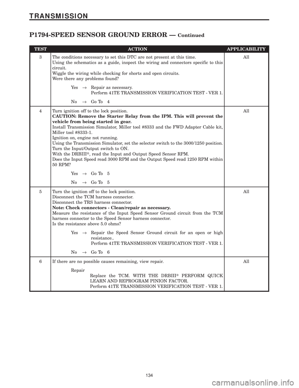
3 The conditions necessary to set this DTC are not present at this time.
Using the schematics as a guide, inspect the wiring and connectors specific to this
circuit.
Wiggle the wiring while checking for shorts and open circuits.
Were there any problems found?All
Ye s®Repair as necessary.
Perform 41TE TRANSMISSION VERIFICATION TEST - VER 1.
No®Go To 4
4 Turn ignition off to the lock position.
CAUTION: Remove the Starter Relay from the IPM. This will prevent the
vehicle from being started in gear.
Install Transmission Simulator, Miller tool #8333 and the FWD Adapter Cable kit,
Miller tool #8333-1.
Ignition on, engine not running.
Using the Transmission Simulator, set the selector switch to the 3000/1250 position.
Turn the Input/Output switch to ON.
With the DRBIIIt, read the Input and Output Speed Sensor RPM.
Does the Input Speed read 3000 RPM and the Output Speed read 1250 RPM within
50 RPM?All
Ye s®Go To 5
No®Go To 5
5 Turn the ignition off to the lock position.
Disconnect the TCM harness connector.
Disconnect the TRS harness connector.
Note: Check connectors - Clean/repair as necessary.
Measure the resistance of the Input Speed Sensor Ground circuit from the TCM
harness connector to the Speed Sensor harness connector.
Is the resistance above 5.0 ohms?All
Ye s®Repair the Speed Sensor Ground circuit for an open or high
resistance..
Perform 41TE TRANSMISSION VERIFICATION TEST - VER 1.
No®Go To 6
6 If there are no possible causes remaining, view repair. All
Repair
Replace the TCM. WITH THE DRBIIItPERFORM QUICK
LEARN AND REPROGRAM PINION FACTOR.
Perform 41TE TRANSMISSION VERIFICATION TEST - VER 1.
134
TRANSMISSION
P1794-SPEED SENSOR GROUND ERROR ÐContinued
Page 4243 of 4284
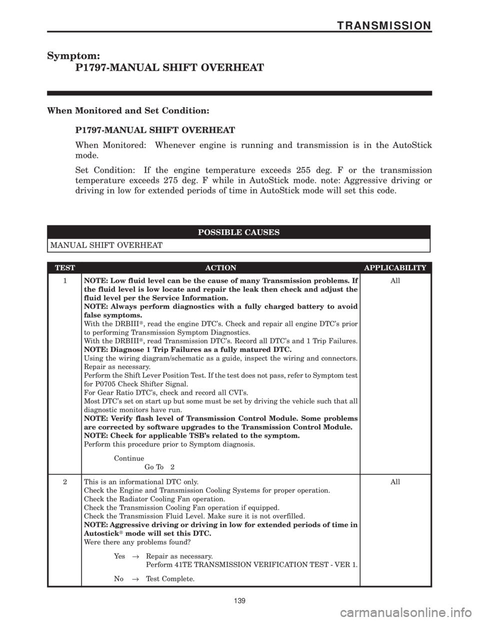
Symptom:
P1797-MANUAL SHIFT OVERHEAT
When Monitored and Set Condition:
P1797-MANUAL SHIFT OVERHEAT
When Monitored: Whenever engine is running and transmission is in the AutoStick
mode.
Set Condition: If the engine temperature exceeds 255 deg. F or the transmission
temperature exceeds 275 deg. F while in AutoStick mode. note: Aggressive driving or
driving in low for extended periods of time in AutoStick mode will set this code.
POSSIBLE CAUSES
MANUAL SHIFT OVERHEAT
TEST ACTION APPLICABILITY
1NOTE: Low fluid level can be the cause of many Transmission problems. If
the fluid level is low locate and repair the leak then check and adjust the
fluid level per the Service Information.
NOTE: Always perform diagnostics with a fully charged battery to avoid
false symptoms.
With the DRBIIIt, read the engine DTC's. Check and repair all engine DTC's prior
to performing Transmission Symptom Diagnostics.
With the DRBIIIt, read Transmission DTC's. Record all DTC's and 1 Trip Failures.
NOTE: Diagnose 1 Trip Failures as a fully matured DTC.
Using the wiring diagram/schematic as a guide, inspect the wiring and connectors.
Repair as necessary.
Perform the Shift Lever Position Test. If the test does not pass, refer to Symptom test
for P0705 Check Shifter Signal.
For Gear Ratio DTC's, check and record all CVI's.
Most DTC's set on start up but some must be set by driving the vehicle such that all
diagnostic monitors have run.
NOTE: Verify flash level of Transmission Control Module. Some problems
are corrected by software upgrades to the Transmission Control Module.
NOTE: Check for applicable TSB's related to the symptom.
Perform this procedure prior to Symptom diagnosis.All
Continue
Go To 2
2 This is an informational DTC only.
Check the Engine and Transmission Cooling Systems for proper operation.
Check the Radiator Cooling Fan operation.
Check the Transmission Cooling Fan operation if equipped.
Check the Transmission Fluid Level. Make sure it is not overfilled.
NOTE: Aggressive driving or driving in low for extended periods of time in
Autosticktmode will set this DTC.
Were there any problems found?All
Ye s®Repair as necessary.
Perform 41TE TRANSMISSION VERIFICATION TEST - VER 1.
No®Test Complete.
139
TRANSMISSION
Page 4244 of 4284
Symptom:
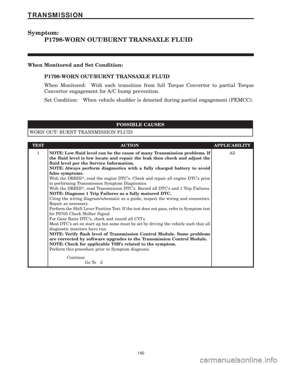
P1798-WORN OUT/BURNT TRANSAXLE FLUID
When Monitored and Set Condition:
P1798-WORN OUT/BURNT TRANSAXLE FLUID
When Monitored: With each transition from full Torque Convertor to partial Torque
Convertor engagement for A/C bump prevention.
Set Condition: When vehicle shudder is detected during partial engagement (PEMCC).
POSSIBLE CAUSES
WORN OUT/ BURNT TRANSMISSION FLUID
TEST ACTION APPLICABILITY
1NOTE: Low fluid level can be the cause of many Transmission problems. If
the fluid level is low locate and repair the leak then check and adjust the
fluid level per the Service Information.
NOTE: Always perform diagnostics with a fully charged battery to avoid
false symptoms.
With the DRBIIIt, read the engine DTC's. Check and repair all engine DTC's prior
to performing Transmission Symptom Diagnostics.
With the DRBIIIt, read Transmission DTC's. Record all DTC's and 1 Trip Failures.
NOTE: Diagnose 1 Trip Failures as a fully matured DTC.
Using the wiring diagram/schematic as a guide, inspect the wiring and connectors.
Repair as necessary.
Perform the Shift Lever Position Test. If the test does not pass, refer to Symptom test
for P0705 Check Shifter Signal.
For Gear Ratio DTC's, check and record all CVI's.
Most DTC's set on start up but some must be set by driving the vehicle such that all
diagnostic monitors have run.
NOTE: Verify flash level of Transmission Control Module. Some problems
are corrected by software upgrades to the Transmission Control Module.
NOTE: Check for applicable TSB's related to the symptom.
Perform this procedure prior to Symptom diagnosis.All
Continue
Go To 2
140
TRANSMISSION
Page 4245 of 4284
TEST ACTION APPLICABILITY
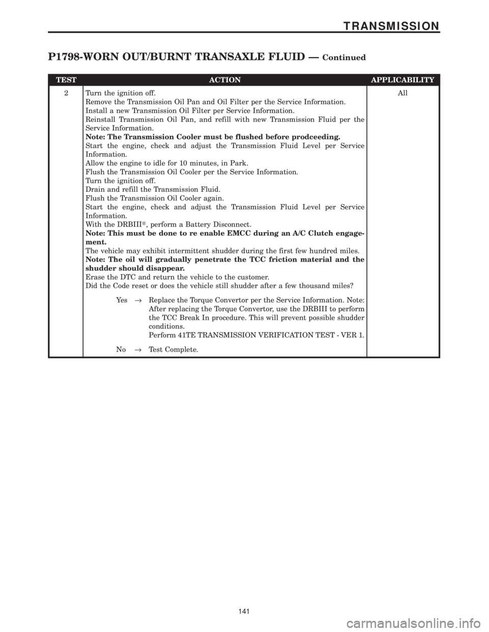
2 Turn the ignition off.
Remove the Transmission Oil Pan and Oil Filter per the Service Information.
Install a new Transmission Oil Filter per Service Information.
Reinstall Transmission Oil Pan, and refill with new Transmission Fluid per the
Service Information.
Note: The Transmission Cooler must be flushed before prodceeding.
Start the engine, check and adjust the Transmission Fluid Level per Service
Information.
Allow the engine to idle for 10 minutes, in Park.
Flush the Transmission Oil Cooler per the Service Information.
Turn the ignition off.
Drain and refill the Transmission Fluid.
Flush the Transmission Oil Cooler again.
Start the engine, check and adjust the Transmission Fluid Level per Service
Information.
With the DRBIIIt, perform a Battery Disconnect.
Note: This must be done to re enable EMCC during an A/C Clutch engage-
ment.
The vehicle may exhibit intermittent shudder during the first few hundred miles.
Note: The oil will gradually penetrate the TCC friction material and the
shudder should disappear.
Erase the DTC and return the vehicle to the customer.
Did the Code reset or does the vehicle still shudder after a few thousand miles?All
Ye s®Replace the Torque Convertor per the Service Information. Note:
After replacing the Torque Convertor, use the DRBIII to perform
the TCC Break In procedure. This will prevent possible shudder
conditions.
Perform 41TE TRANSMISSION VERIFICATION TEST - VER 1.
No®Test Complete.
141
TRANSMISSION
P1798-WORN OUT/BURNT TRANSAXLE FLUID ÐContinued
Page 4246 of 4284
Symptom:
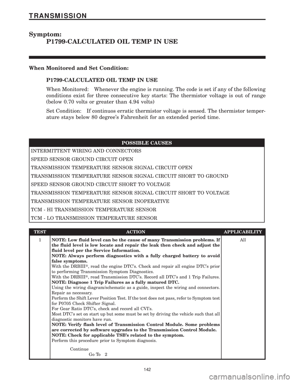
P1799-CALCULATED OIL TEMP IN USE
When Monitored and Set Condition:
P1799-CALCULATED OIL TEMP IN USE
When Monitored: Whenever the engine is running. The code is set if any of the following
conditions exist for three consecutive key starts: The thermistor voltage is out of range
(below 0.70 volts or greater than 4.94 volts)
Set Condition: If continuos erratic thermistor voltage is sensed. The thermistor temper-
ature stays below 80 degree's Fahrenheit for an extended period time.
POSSIBLE CAUSES
INTERMITTENT WIRING AND CONNECTORS
SPEED SENSOR GROUND CIRCUIT OPEN
TRANSMISSION TEMPERATURE SENSOR SIGNAL CIRCUIT OPEN
TRANSMISSION TEMPERATURE SENSOR SIGNAL CIRCUIT SHORT TO GROUND
SPEED SENSOR GROUND CIRCUIT SHORT TO VOLTAGE
TRANSMISSION TEMPERATURE SENSOR SIGNAL CIRCUIT SHORT TO VOLTAGE
TRANSMISSION TEMPERATURE SENSOR INOPERATIVE
TCM - HI TRANSMISSION TEMPERATURE SENSOR
TCM - LO TRANSMISSION TEMPERATURE SENSOR
TEST ACTION APPLICABILITY
1NOTE: Low fluid level can be the cause of many Transmission problems. If
the fluid level is low locate and repair the leak then check and adjust the
fluid level per the Service Information.
NOTE: Always perform diagnostics with a fully charged battery to avoid
false symptoms.
With the DRBIIIt, read the engine DTC's. Check and repair all engine DTC's prior
to performing Transmission Symptom Diagnostics.
With the DRBIIIt, read Transmission DTC's. Record all DTC's and 1 Trip Failures.
NOTE: Diagnose 1 Trip Failures as a fully matured DTC.
Using the wiring diagram/schematic as a guide, inspect the wiring and connectors.
Repair as necessary.
Perform the Shift Lever Position Test. If the test does not pass, refer to Symptom test
for P0705 Check Shifter Signal.
For Gear Ratio DTC's, check and record all CVI's.
Most DTC's set on start up but some must be set by driving the vehicle such that all
diagnostic monitors have run.
NOTE: Verify flash level of Transmission Control Module. Some problems
are corrected by software upgrades to the Transmission Control Module.
NOTE: Check for applicable TSB's related to the symptom.
Perform this procedure prior to Symptom diagnosis.All
Continue
Go To 2
142
TRANSMISSION