2001 CHRYSLER VOYAGER brake sensor
[x] Cancel search: brake sensorPage 3941 of 4284
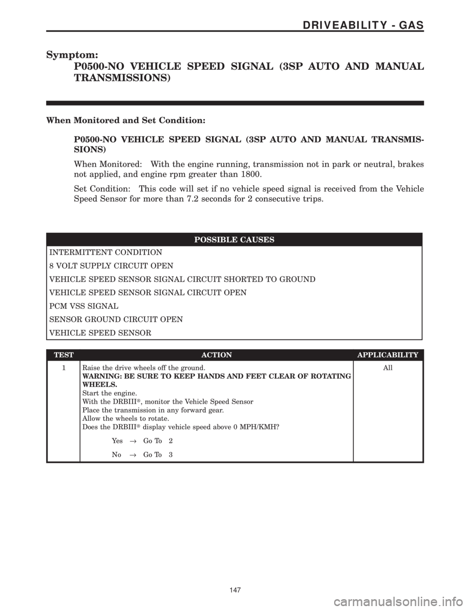
Symptom:
P0500-NO VEHICLE SPEED SIGNAL (3SP AUTO AND MANUAL
TRANSMISSIONS)
When Monitored and Set Condition:
P0500-NO VEHICLE SPEED SIGNAL (3SP AUTO AND MANUAL TRANSMIS-
SIONS)
When Monitored: With the engine running, transmission not in park or neutral, brakes
not applied, and engine rpm greater than 1800.
Set Condition: This code will set if no vehicle speed signal is received from the Vehicle
Speed Sensor for more than 7.2 seconds for 2 consecutive trips.
POSSIBLE CAUSES
INTERMITTENT CONDITION
8 VOLT SUPPLY CIRCUIT OPEN
VEHICLE SPEED SENSOR SIGNAL CIRCUIT SHORTED TO GROUND
VEHICLE SPEED SENSOR SIGNAL CIRCUIT OPEN
PCM VSS SIGNAL
SENSOR GROUND CIRCUIT OPEN
VEHICLE SPEED SENSOR
TEST ACTION APPLICABILITY
1 Raise the drive wheels off the ground.
WARNING: BE SURE TO KEEP HANDS AND FEET CLEAR OF ROTATING
WHEELS.
Start the engine.
With the DRBIIIt, monitor the Vehicle Speed Sensor
Place the transmission in any forward gear.
Allow the wheels to rotate.
Does the DRBIIItdisplay vehicle speed above 0 MPH/KMH?All
Ye s®Go To 2
No®Go To 3
147
DRIVEABILITY - GAS
Page 3944 of 4284
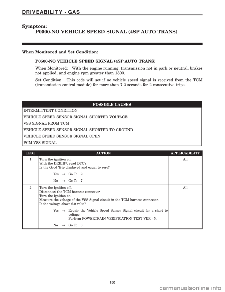
Symptom:
P0500-NO VEHICLE SPEED SIGNAL (4SP AUTO TRANS)
When Monitored and Set Condition:
P0500-NO VEHICLE SPEED SIGNAL (4SP AUTO TRANS)
When Monitored: With the engine running, transmission not in park or neutral, brakes
not applied, and engine rpm greater than 1800.
Set Condition: This code will set if no vehicle speed signal is received from the TCM
(transmission control module) for more than 7.2 seconds for 2 consecutive trips.
POSSIBLE CAUSES
INTERMITTENT CONDITION
VEHICLE SPEED SENSOR SIGNAL SHORTED VOLTAGE
VSS SIGNAL FROM TCM
VEHICLE SPEED SENSOR SIGNAL SHORTED TO GROUND
VEHICLE SPEED SENSOR SIGNAL OPEN
PCM VSS SIGNAL
TEST ACTION APPLICABILITY
1 Turn the ignition on.
With the DRBIIIt, read DTC's.
Is the Good Trip displayed and equal to zero?All
Ye s®Go To 2
No®Go To 7
2 Turn the ignition off.
Disconnect the TCM harness connector.
Turn the ignition on.
Measure the voltage of the VSS Signal circuit in the TCM harness connector.
Is the voltage above 6.0 volts?All
Ye s®Repair the Vehicle Speed Sensor Signal circuit for a short to
voltage.
Perform POWERTRAIN VERIFICATION TEST VER - 5.
No®Go To 3
150
DRIVEABILITY - GAS
Page 3987 of 4284
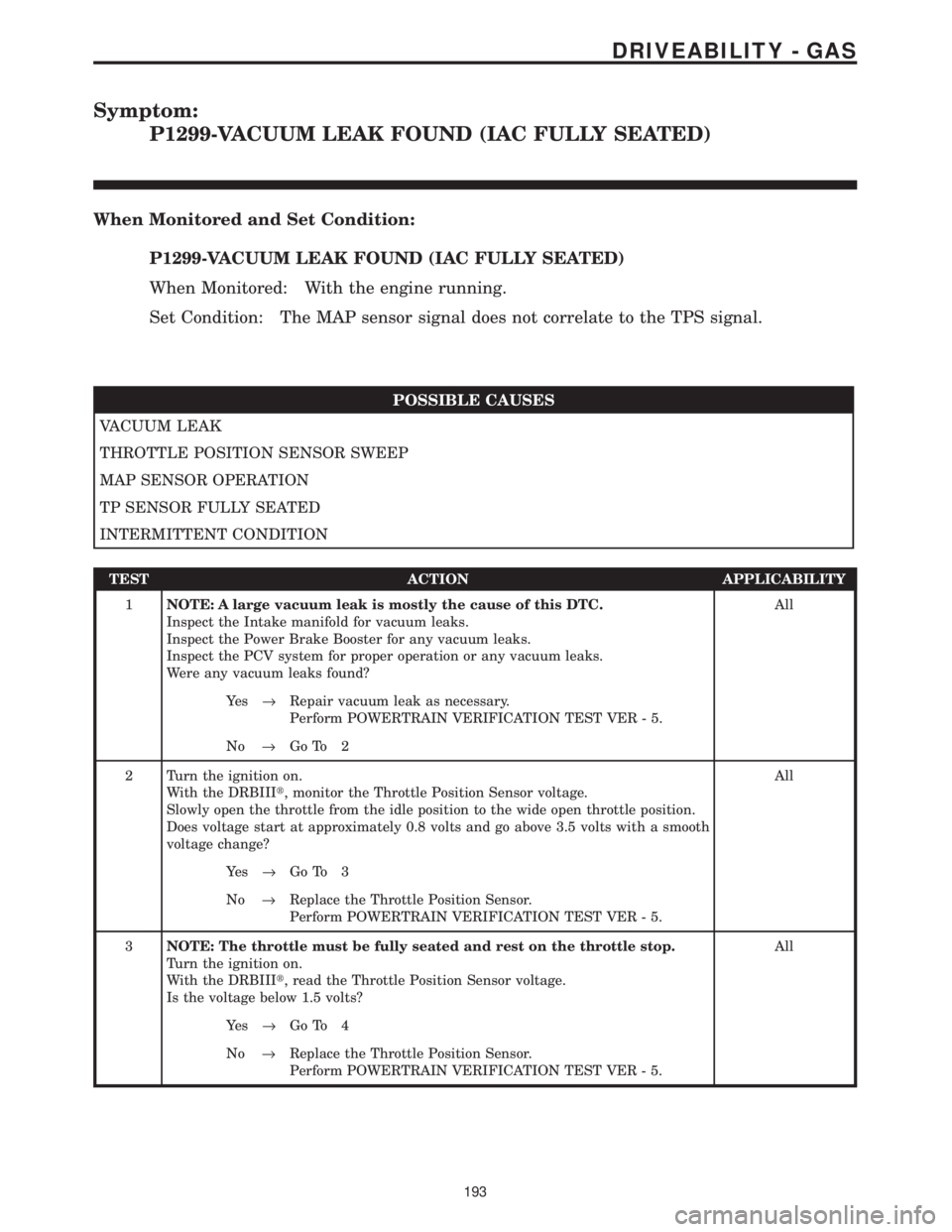
Symptom:
P1299-VACUUM LEAK FOUND (IAC FULLY SEATED)
When Monitored and Set Condition:
P1299-VACUUM LEAK FOUND (IAC FULLY SEATED)
When Monitored: With the engine running.
Set Condition: The MAP sensor signal does not correlate to the TPS signal.
POSSIBLE CAUSES
VACUUM LEAK
THROTTLE POSITION SENSOR SWEEP
MAP SENSOR OPERATION
TP SENSOR FULLY SEATED
INTERMITTENT CONDITION
TEST ACTION APPLICABILITY
1NOTE: A large vacuum leak is mostly the cause of this DTC.
Inspect the Intake manifold for vacuum leaks.
Inspect the Power Brake Booster for any vacuum leaks.
Inspect the PCV system for proper operation or any vacuum leaks.
Were any vacuum leaks found?All
Ye s®Repair vacuum leak as necessary.
Perform POWERTRAIN VERIFICATION TEST VER - 5.
No®Go To 2
2 Turn the ignition on.
With the DRBIIIt, monitor the Throttle Position Sensor voltage.
Slowly open the throttle from the idle position to the wide open throttle position.
Does voltage start at approximately 0.8 volts and go above 3.5 volts with a smooth
voltage change?All
Ye s®Go To 3
No®Replace the Throttle Position Sensor.
Perform POWERTRAIN VERIFICATION TEST VER - 5.
3NOTE: The throttle must be fully seated and rest on the throttle stop.
Turn the ignition on.
With the DRBIIIt, read the Throttle Position Sensor voltage.
Is the voltage below 1.5 volts?All
Ye s®Go To 4
No®Replace the Throttle Position Sensor.
Perform POWERTRAIN VERIFICATION TEST VER - 5.
193
DRIVEABILITY - GAS
Page 4086 of 4284
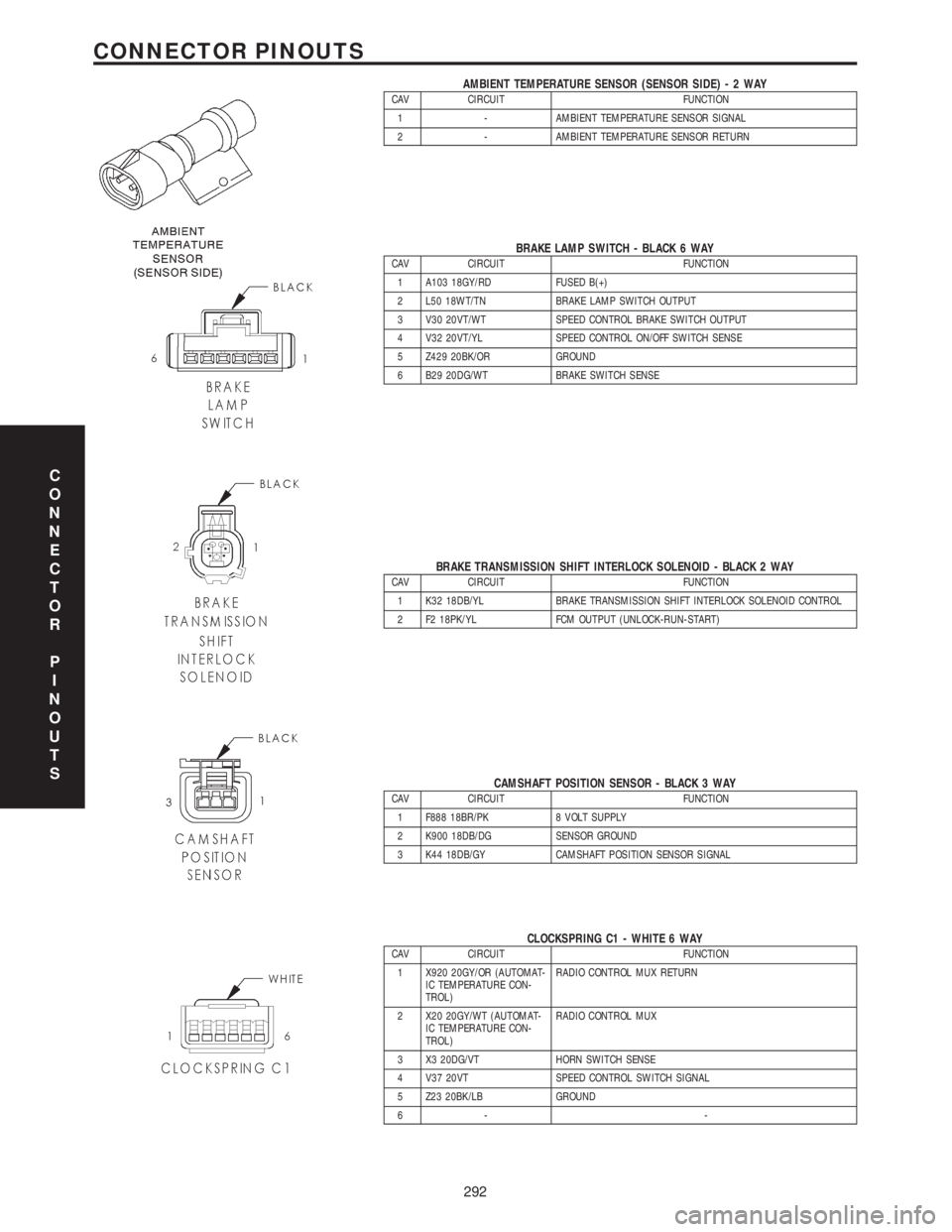
AMBIENT TEMPERATURE SENSOR (SENSOR SIDE)-2WAYCAV CIRCUIT FUNCTION
1 - AMBIENT TEMPERATURE SENSOR SIGNAL
2 - AMBIENT TEMPERATURE SENSOR RETURN
BRAKE LAMP SWITCH - BLACK 6 WAYCAV CIRCUIT FUNCTION
1 A103 18GY/RD FUSED B(+)
2 L50 18WT/TN BRAKE LAMP SWITCH OUTPUT
3 V30 20VT/WT SPEED CONTROL BRAKE SWITCH OUTPUT
4 V32 20VT/YL SPEED CONTROL ON/OFF SWITCH SENSE
5 Z429 20BK/OR GROUND
6 B29 20DG/WT BRAKE SWITCH SENSE
BRAKE TRANSMISSION SHIFT INTERLOCK SOLENOID - BLACK 2 WAYCAV CIRCUIT FUNCTION
1 K32 18DB/YL BRAKE TRANSMISSION SHIFT INTERLOCK SOLENOID CONTROL
2 F2 18PK/YL FCM OUTPUT (UNLOCK-RUN-START)
CAMSHAFT POSITION SENSOR - BLACK 3 WAYCAV CIRCUIT FUNCTION
1 F888 18BR/PK 8 VOLT SUPPLY
2 K900 18DB/DG SENSOR GROUND
3 K44 18DB/GY CAMSHAFT POSITION SENSOR SIGNAL
CLOCKSPRING C1 - WHITE 6 WAYCAV CIRCUIT FUNCTION
1 X920 20GY/OR (AUTOMAT-
IC TEMPERATURE CON-
TROL)RADIO CONTROL MUX RETURN
2 X20 20GY/WT (AUTOMAT-
IC TEMPERATURE CON-
TROL)RADIO CONTROL MUX
3 X3 20DG/VT HORN SWITCH SENSE
4 V37 20VT SPEED CONTROL SWITCH SIGNAL
5 Z23 20BK/LB GROUND
6- -
C
O
N
N
E
C
T
O
R
P
I
N
O
U
T
S
292
CONNECTOR PINOUTS
Page 4096 of 4284
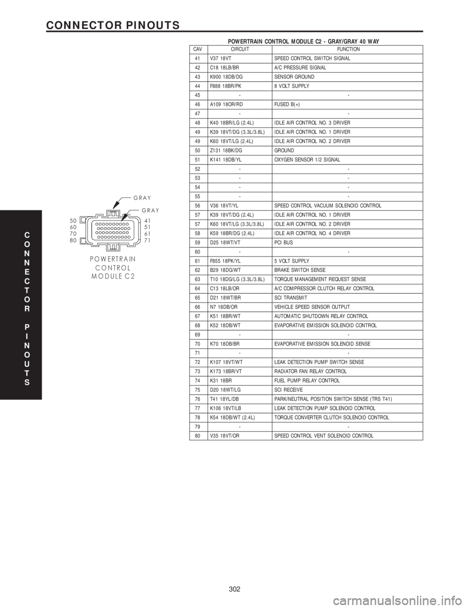
POWERTRAIN CONTROL MODULE C2 - GRAY/GRAY 40 WAYCAV CIRCUIT FUNCTION
41 V37 18VT SPEED CONTROL SWITCH SIGNAL
42 C18 18LB/BR A/C PRESSURE SIGNAL
43 K900 18DB/DG SENSOR GROUND
44 F888 18BR/PK 8 VOLT SUPPLY
45 - -
46 A109 18OR/RD FUSED B(+)
47 - -
48 K40 18BR/LG (2.4L) IDLE AIR CONTROL NO. 3 DRIVER
49 K39 18VT/DG (3.3L/3.8L) IDLE AIR CONTROL NO. 1 DRIVER
49 K60 18VT/LG (2.4L) IDLE AIR CONTROL NO. 2 DRIVER
50 Z131 18BK/DG GROUND
51 K141 18DB/YL OXYGEN SENSOR 1/2 SIGNAL
52 - -
53 - -
54 - -
55 - -
56 V36 18VT/YL SPEED CONTROL VACUUM SOLENOID CONTROL
57 K39 18VT/DG (2.4L) IDLE AIR CONTROL NO. 1 DRIVER
57 K60 18VT/LG (3.3L/3.8L) IDLE AIR CONTROL NO. 2 DRIVER
58 K59 18BR/DG (2.4L) IDLE AIR CONTROL NO. 4 DRIVER
59 D25 18WT/VT PCI BUS
60 - -
61 F855 18PK/YL 5 VOLT SUPPLY
62 B29 18DG/WT BRAKE SWITCH SENSE
63 T10 18DG/LG (3.3L/3.8L) TORQUE MANAGEMENT REQUEST SENSE
64 C13 18LB/OR A/C COMPRESSOR CLUTCH RELAY CONTROL
65 D21 18WT/BR SCI TRANSMIT
66 N7 18DB/OR VEHICLE SPEED SENSOR OUTPUT
67 K51 18BR/WT AUTOMATIC SHUTDOWN RELAY CONTROL
68 K52 18DB/WT EVAPORATIVE EMISSION SOLENOID CONTROL
69 - -
70 K70 18DB/BR EVAPORATIVE EMISSION SOLENOID SENSE
71 - -
72 K107 18VT/WT LEAK DETECTION PUMP SWITCH SENSE
73 K173 18BR/VT RADIATOR FAN RELAY CONTROL
74 K31 18BR FUEL PUMP RELAY CONTROL
75 D20 18WT/LG SCI RECEIVE
76 T41 18YL/DB PARK/NEUTRAL POSITION SWITCH SENSE (TRS T41)
77 K106 18VT/LB LEAK DETECTION PUMP SOLENOID CONTROL
78 K54 18DB/WT (2.4L) TORQUE CONVERTER CLUTCH SOLENOID CONTROL
79 - -
80 V35 18VT/OR SPEED CONTROL VENT SOLENOID CONTROL
C
O
N
N
E
C
T
O
R
P
I
N
O
U
T
S
302
CONNECTOR PINOUTS
Page 4102 of 4284

TABLE OF CONTENTS - Continued
TRANSMISSION
P0120-THROTTLE POSITION SENSOR SIGNAL CIRCUIT.....................24
P0600-SERIAL COMMUNICATION LINK MALFUNCTION.......................26
P0604-INTERNAL TCM..................................................28
P0605-INTERNAL TCM..................................................29
P0700-INTERNAL TCM..................................................30
P0705-CHECK SHIFTER SIGNAL..........................................31
P0715-INPUT SPEED SENSOR ERROR....................................38
P0720-OUTPUT SPEED SENSOR ERROR..................................42
P0725-ENGINE SPEED SENSOR CIRCUIT (3.3L/3.8L)........................46
P0725-ENGINE SPEED SENSOR CIRCUIT (3.5L)............................48
P0731-GEAR RATIO ERROR IN 1ST.......................................51
P0732-GEAR RATIO ERROR IN 2ND.......................................53
P0733-GEAR RATIO ERROR IN 3RD.......................................55
P0734-GEAR RATIO ERROR IN 4TH.......................................57
P0736-GEAR RATIO ERROR IN REVERSE..................................59
P0740-TORQUE CONVERTER CLUTCH CONTROL CIRCUIT...................61
P0750-LR SOLENOID CIRCUIT............................................63
P0755-2-4 SOLENOID CIRCUIT...........................................66
P0760-OD SOLENOID CIRCUIT...........................................69
P0765-UD SOLENOID CIRCUIT...........................................72
P1714-LOW BATTERY VOLTAGE..........................................75
P1716-BUS COMMUNICATION WITH PCM..................................79
P1717-NO COMMUNICATION WITH THE MIC...............................81
P1738-HIGH TEMPERATURE OPERATION ACTIVATED.......................83
P1739-POWER UP AT SPEED............................................85
P1765-SWITCHED BATTERY.............................................86
P1767-TRANSMISSION RELAY ALWAYS ON................................89
P1768-RELAY OUTPUT ALWAYS OFF......................................92
P1775-SOLENOID SWITCH VALVE LATCHED IN TCC POSITION...............96
P1776-SOLENOID SWITCH VALVE LATCHED IN LR POSITION................100
P1781-OD PRESSURE SWITCH SENSE CIRCUIT...........................104
P1782 - 2-4 PRESSURE SWITCH SENSE CIRCUIT..........................107
P1784-LR PRESSURE SWITCH SENSE CIRCUIT...........................110
P1787-OD HYDRAULIC PRESSURE TEST FAILURE.........................114
P1788-2/4 HYDRAULIC PRESSURE TEST FAILURE.........................118
P1789-2-4/OD HYDRAULIC PRESSURE TEST FAILURE......................122
P1790-FAULT IMMEDIATELY AFTER SHIFT................................123
P1791-LOSS OF PRIME.................................................124
P1792-BATTERY WAS DISCONNECTED...................................127
P1793-TRD LINK COMMUNICATION ERROR...............................130
P1794-SPEED SENSOR GROUND ERROR................................133
P1795-INTERNAL TCM.................................................135
P1796-AUTOSTICK SENSOR CIRCUIT....................................136
P1797-MANUAL SHIFT OVERHEAT.......................................139
P1798-WORN OUT/BURNT TRANSAXLE FLUID.............................140
P1799-CALCULATED OIL TEMP IN USE...................................142
*BRAKE SHIFT INTERLOCK OUTPUT OPEN...............................146
*CHECKING PARK/NEUTRAL SWITCH OPERATION.........................148
*INCORRECT TRANSMISSION FLUID LEVEL...............................150
*NO BACK UP LAMP OPERATION........................................151
*NO SPEEDOMETER OPERATION........................................153
*TRANSMISSION NOISY WITH NO DTC'S PRESENT........................154
ii
Page 4103 of 4284
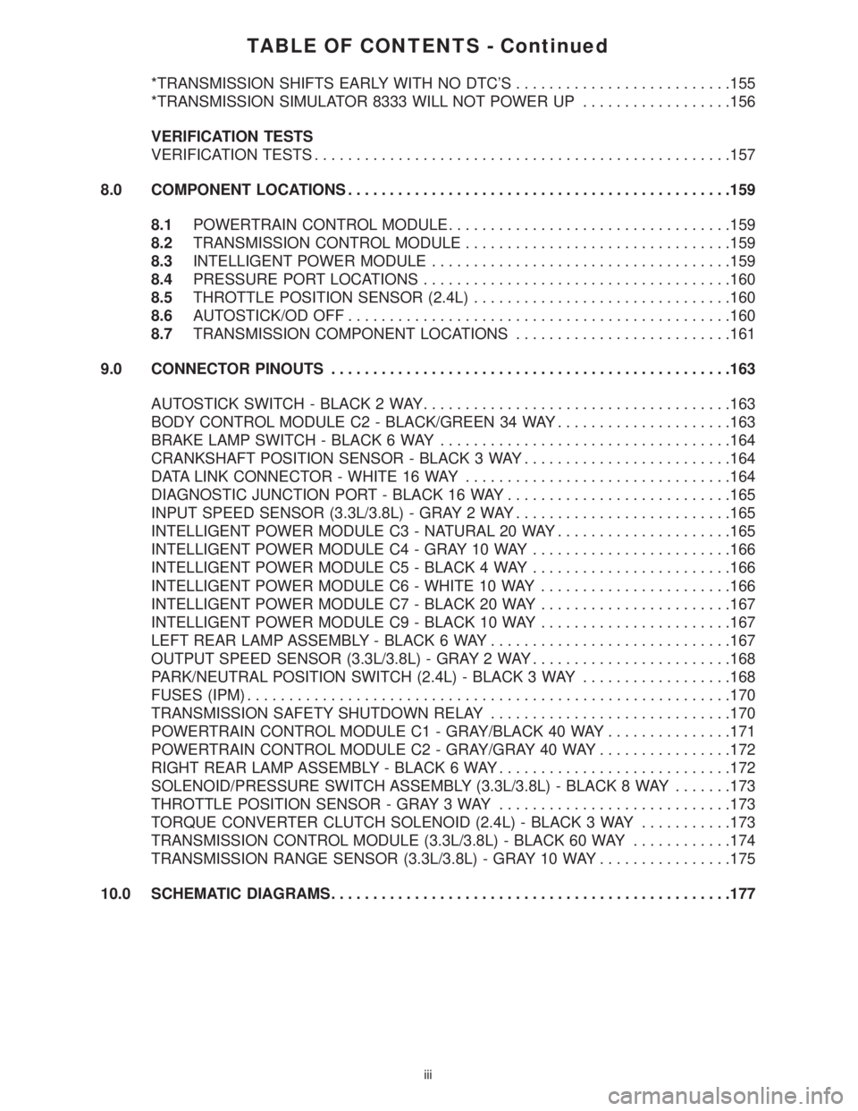
TABLE OF CONTENTS - Continued
*TRANSMISSION SHIFTS EARLY WITH NO DTC'S..........................155
*TRANSMISSION SIMULATOR 8333 WILL NOT POWER UP..................156
VERIFICATION TESTS
VERIFICATION TESTS..................................................157
8.0 COMPONENT LOCATIONS..............................................159
8.1POWERTRAIN CONTROL MODULE..................................159
8.2TRANSMISSION CONTROL MODULE................................159
8.3INTELLIGENT POWER MODULE....................................159
8.4PRESSURE PORT LOCATIONS.....................................160
8.5THROTTLE POSITION SENSOR (2.4L)...............................160
8.6AUTOSTICK/OD OFF..............................................160
8.7TRANSMISSION COMPONENT LOCATIONS..........................161
9.0 CONNECTOR PINOUTS................................................163
AUTOSTICK SWITCH - BLACK 2 WAY.....................................163
BODY CONTROL MODULE C2 - BLACK/GREEN 34 WAY.....................163
BRAKE LAMP SWITCH - BLACK 6 WAY...................................164
CRANKSHAFT POSITION SENSOR - BLACK 3 WAY.........................164
DATA LINK CONNECTOR - WHITE 16 WAY................................164
DIAGNOSTIC JUNCTION PORT - BLACK 16 WAY...........................165
INPUT SPEED SENSOR (3.3L/3.8L) - GRAY 2 WAY..........................165
INTELLIGENT POWER MODULE C3 - NATURAL 20 WAY.....................165
INTELLIGENT POWER MODULE C4 - GRAY 10 WAY........................166
INTELLIGENT POWER MODULE C5 - BLACK 4 WAY........................166
INTELLIGENT POWER MODULE C6 - WHITE 10 WAY.......................166
INTELLIGENT POWER MODULE C7 - BLACK 20 WAY.......................167
INTELLIGENT POWER MODULE C9 - BLACK 10 WAY.......................167
LEFT REAR LAMP ASSEMBLY - BLACK 6 WAY.............................167
OUTPUT SPEED SENSOR (3.3L/3.8L) - GRAY 2 WAY........................168
PARK/NEUTRAL POSITION SWITCH (2.4L) - BLACK 3 WAY..................168
FUSES (IPM)..........................................................170
TRANSMISSION SAFETY SHUTDOWN RELAY.............................170
POWERTRAIN CONTROL MODULE C1 - GRAY/BLACK 40 WAY...............171
POWERTRAIN CONTROL MODULE C2 - GRAY/GRAY 40 WAY................172
RIGHT REAR LAMP ASSEMBLY - BLACK 6 WAY............................172
SOLENOID/PRESSURE SWITCH ASSEMBLY (3.3L/3.8L) - BLACK 8 WAY.......173
THROTTLE POSITION SENSOR - GRAY 3 WAY............................173
TORQUE CONVERTER CLUTCH SOLENOID (2.4L) - BLACK 3 WAY...........173
TRANSMISSION CONTROL MODULE (3.3L/3.8L) - BLACK 60 WAY............174
TRANSMISSION RANGE SENSOR (3.3L/3.8L) - GRAY 10 WAY................175
10.0 SCHEMATIC DIAGRAMS................................................177
iii
Page 4107 of 4284
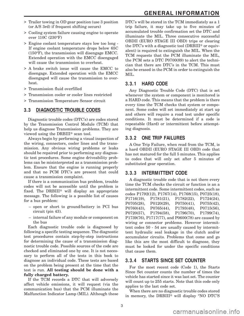
> Trailer towing in OD gear position (use 3 position
(or A/S 3rd) if frequent shifting occurs)
> Cooling system failure causing engine to operate
over 110C (230ÉF)
> Engine coolant temperature stays low too long -
If engine coolant temperature drops below 65C
(150ÉF), the transmission will disengage EMCC.
Extended operation with the EMCC disengaged
will cause the transmission to overheat.
> A brake switch issue will cause the EMCC to
disengage. Extended operation with the EMCC
disengaged will cause the transmission to over-
heat.
> Transmission fluid overfilled
> Transmission cooler or cooler lines restricted
> Transmission Temperature Sensor circuit
3.3 DIAGNOSTIC TROUBLE CODES
Diagnostic trouble codes (DTC's) are codes stored
by the Transmission Control Module (TCM) that
help us diagnose Transmission problems. They are
viewed using the DRBIIItscan tool.
Always begin by performing a visual inspection of
the wiring, connectors, cooler lines and the trans-
mission. Any obvious wiring problems or leaks
should be repaired prior to performing any diagnos-
tic test procedures. Some engine driveability prob-
lems can be misinterpreted as a transmission prob-
lem. Ensure that the engine is running properly
and that no PCM DTC's are present that could
cause a transmission complaint.
If there is a communication bus problem, trouble
codes will not be accessible until the problem is
fixed. The DRBIIItwill display an appropriate
message. The following is a possible list of causes
for a bus problem:
± open or short to ground/battery in PCI bus
circuit (pin 43).
± internal failure of any module or component on
the bus
Each diagnostic trouble code is diagnosed by
following a specific testing sequence. The diagnostic
test procedures contain step-by-step instructions
for determining the cause of a transmission diag-
nostic trouble code. Possible sources of the code are
checked and eliminated one by one. It is not neces-
sary to perform all of the tests in this book to
diagnose an individual code. These tests are based
on the problem being present at the time that the
test is run.All testing should be done with a
fully charged battery.
If the TCM records a DTC that will adversely
affect vehicle emissions, it will request (via the
communication bus) that the PCM illuminate the
Malfunction Indicator Lamp (MIL). Although theseDTC's will be stored in the TCM immediately as a 1
trip failure, it may take up to five minutes of
accumulated trouble confirmation set the DTC and
illuminate the MIL. Three consecutive successful
OBDII (EURO STAGE III OBD) trips or clearing
the DTC's with a diagnostic tool (DRBIIItor equiv-
alent) is required to extinguish the MIL. When the
TCM requests that the PCM illuminate the MIL,
the PCM sets a DTC P0700(89) to alert the techni-
cian that there are DTC's in the TCM. This must
also be erased in the PCM in order to extinguish the
MIL.
3.3.1 HARD CODE
Any Diagnostic Trouble Code (DTC) that is set
whenever the system or component is monitored is
a HARD code. This means that the problem is there
every time the TCM checks that system or compo-
nent. Some codes will set immediately at start up
and others will require a road test under specific
conditions. It must be determined if a code is
repeatable (Hard) or intermittent before attempt-
ing diagnosis.
3.3.2 ONE TRIP FAILURES
A One Trip Failure, when read from the TCM, is
a hard OBDII (EURO STAGE III OBD) code that
has not matured for the full 5 minutes. This applies
to codes that will only set after 5 minutes of
substituted gear operation.
3.3.3 INTERMITTENT CODE
A diagnostic trouble code that is not there every
time the TCM checks the circuit or function is an a
intermittent code. Some intermittent codes, such as
codes P1792(12), P1767(14), P1768(15), P0725(18),
P1716(19), P1781(21), P1782(22), P1724(24),
P0705(28), P0120(29), P0750(41), P0755(42),
P0760(43), P0765(44), P1793(48), P0715(56),
P0720(57), P1794(58), P1796(70), P1799(74),
P1739(76), P1717(77), and P0600(78) are caused by
wiring or connector problems. However intermit-
tent codes 50 - 54 are usually caused by intermit-
tent hydraulic seal leakage in the clutch and/or
accumulator circuits. Problems that come and go
like this are the most difficult to diagnose, they
must be looked for under the specific conditions
that cause them.
3.3.4 STARTS SINCE SET COUNTER
For the most recent code (Code 1), the Starts
Since Set counter counts the number of times the
vehicle has started since it was last set. The counter
will count up to 255 starts. Note that this code only
applies to the last code set.
When there are no diagnostic trouble codes stored
in memory, the DRBIIItwill display ``NO DTC'S
3
GENERAL INFORMATION