2001 CHRYSLER VOYAGER brake sensor
[x] Cancel search: brake sensorPage 4121 of 4284

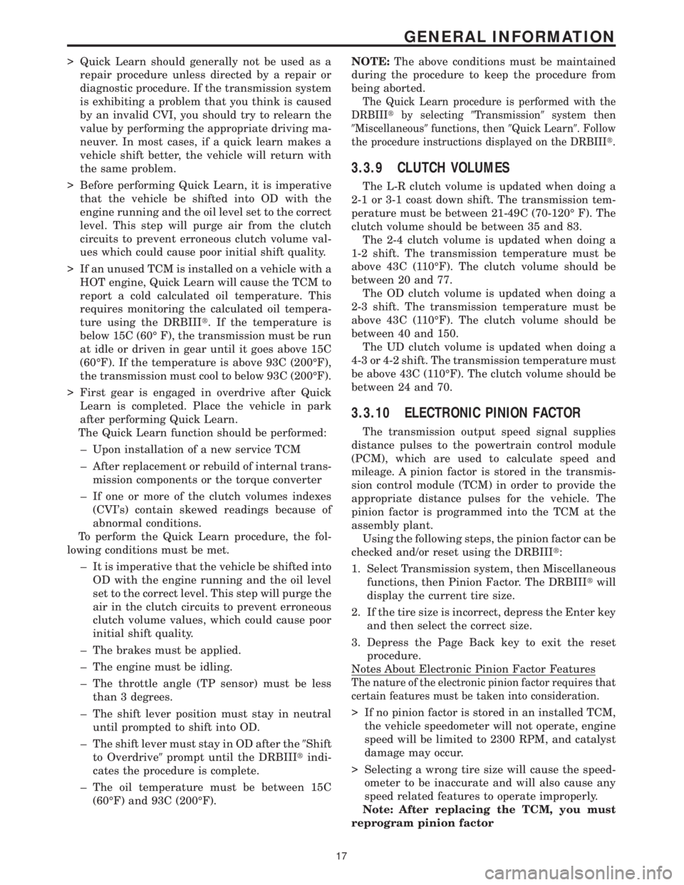
> Quick Learn should generally not be used as a
repair procedure unless directed by a repair or
diagnostic procedure. If the transmission system
is exhibiting a problem that you think is caused
by an invalid CVI, you should try to relearn the
value by performing the appropriate driving ma-
neuver. In most cases, if a quick learn makes a
vehicle shift better, the vehicle will return with
the same problem.
> Before performing Quick Learn, it is imperative
that the vehicle be shifted into OD with the
engine running and the oil level set to the correct
level. This step will purge air from the clutch
circuits to prevent erroneous clutch volume val-
ues which could cause poor initial shift quality.
> If an unused TCM is installed on a vehicle with a
HOT engine, Quick Learn will cause the TCM to
report a cold calculated oil temperature. This
requires monitoring the calculated oil tempera-
ture using the DRBIIIt. If the temperature is
below 15C (60É F), the transmission must be run
at idle or driven in gear until it goes above 15C
(60ÉF). If the temperature is above 93C (200ÉF),
the transmission must cool to below 93C (200ÉF).
> First gear is engaged in overdrive after Quick
Learn is completed. Place the vehicle in park
after performing Quick Learn.
The Quick Learn function should be performed:
± Upon installation of a new service TCM
± After replacement or rebuild of internal trans-
mission components or the torque converter
± If one or more of the clutch volumes indexes
(CVI's) contain skewed readings because of
abnormal conditions.
To perform the Quick Learn procedure, the fol-
lowing conditions must be met.
± It is imperative that the vehicle be shifted into
OD with the engine running and the oil level
set to the correct level. This step will purge the
air in the clutch circuits to prevent erroneous
clutch volume values, which could cause poor
initial shift quality.
± The brakes must be applied.
± The engine must be idling.
± The throttle angle (TP sensor) must be less
than 3 degrees.
± The shift lever position must stay in neutral
until prompted to shift into OD.
± The shift lever must stay in OD after the9Shift
to Overdrive9prompt until the DRBIIItindi-
cates the procedure is complete.
± The oil temperature must be between 15C
(60ÉF) and 93C (200ÉF).NOTE:The above conditions must be maintained
during the procedure to keep the procedure from
being aborted.
The Quick Learn procedure is performed with the
DRBIIItby selecting9Transmission9system then
9Miscellaneous9functions, then9Quick Learn9. Follow
the procedure instructions displayed on the DRBIIIt.
3.3.9 CLUTCH VOLUMES
The L-R clutch volume is updated when doing a
2-1 or 3-1 coast down shift. The transmission tem-
perature must be between 21-49C (70-120É F). The
clutch volume should be between 35 and 83.
The 2-4 clutch volume is updated when doing a
1-2 shift. The transmission temperature must be
above 43C (110ÉF). The clutch volume should be
between 20 and 77.
The OD clutch volume is updated when doing a
2-3 shift. The transmission temperature must be
above 43C (110ÉF). The clutch volume should be
between 40 and 150.
The UD clutch volume is updated when doing a
4-3 or 4-2 shift. The transmission temperature must
be above 43C (110ÉF). The clutch volume should be
between 24 and 70.
3.3.10 ELECTRONIC PINION FACTOR
The transmission output speed signal supplies
distance pulses to the powertrain control module
(PCM), which are used to calculate speed and
mileage. A pinion factor is stored in the transmis-
sion control module (TCM) in order to provide the
appropriate distance pulses for the vehicle. The
pinion factor is programmed into the TCM at the
assembly plant.
Using the following steps, the pinion factor can be
checked and/or reset using the DRBIIIt:
1. Select Transmission system, then Miscellaneous
functions, then Pinion Factor. The DRBIIItwill
display the current tire size.
2. If the tire size is incorrect, depress the Enter key
and then select the correct size.
3. Depress the Page Back key to exit the reset
procedure.
Notes About Electronic Pinion Factor Features
The nature of the electronic pinion factor requires that
certain features must be taken into consideration.
> If no pinion factor is stored in an installed TCM,
the vehicle speedometer will not operate, engine
speed will be limited to 2300 RPM, and catalyst
damage may occur.
> Selecting a wrong tire size will cause the speed-
ometer to be inaccurate and will also cause any
speed related features to operate improperly.
Note: After replacing the TCM, you must
reprogram pinion factor
17
GENERAL INFORMATION
Page 4147 of 4284

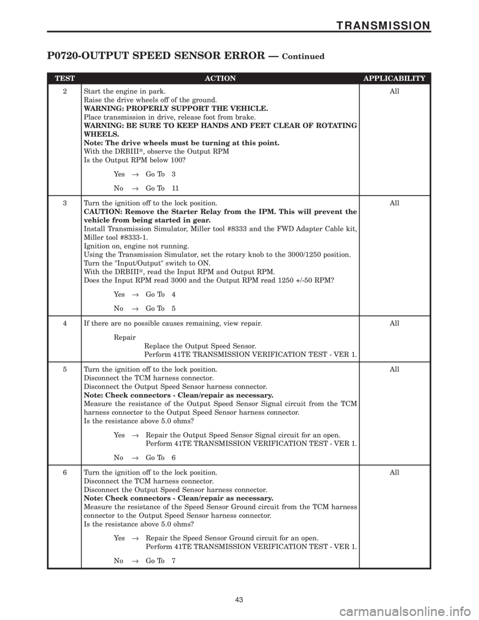
TEST ACTION APPLICABILITY
2 Start the engine in park.
Raise the drive wheels off of the ground.
WARNING: PROPERLY SUPPORT THE VEHICLE.
Place transmission in drive, release foot from brake.
WARNING: BE SURE TO KEEP HANDS AND FEET CLEAR OF ROTATING
WHEELS.
Note: The drive wheels must be turning at this point.
With the DRBIIIt, observe the Output RPM
Is the Output RPM below 100?All
Ye s®Go To 3
No®Go To 11
3 Turn the ignition off to the lock position.
CAUTION: Remove the Starter Relay from the IPM. This will prevent the
vehicle from being started in gear.
Install Transmission Simulator, Miller tool #8333 and the FWD Adapter Cable kit,
Miller tool #8333-1.
Ignition on, engine not running.
Using the Transmission Simulator, set the rotary knob to the 3000/1250 position.
Turn the9Input/Output9switch to ON.
With the DRBIIIt, read the Input RPM and Output RPM.
Does the Input RPM read 3000 and the Output RPM read 1250 +/-50 RPM?All
Ye s®Go To 4
No®Go To 5
4 If there are no possible causes remaining, view repair. All
Repair
Replace the Output Speed Sensor.
Perform 41TE TRANSMISSION VERIFICATION TEST - VER 1.
5 Turn the ignition off to the lock position.
Disconnect the TCM harness connector.
Disconnect the Output Speed Sensor harness connector.
Note: Check connectors - Clean/repair as necessary.
Measure the resistance of the Output Speed Sensor Signal circuit from the TCM
harness connector to the Output Speed Sensor harness connector.
Is the resistance above 5.0 ohms?All
Ye s®Repair the Output Speed Sensor Signal circuit for an open.
Perform 41TE TRANSMISSION VERIFICATION TEST - VER 1.
No®Go To 6
6 Turn the ignition off to the lock position.
Disconnect the TCM harness connector.
Disconnect the Output Speed Sensor harness connector.
Note: Check connectors - Clean/repair as necessary.
Measure the resistance of the Speed Sensor Ground circuit from the TCM harness
connector to the Output Speed Sensor harness connector.
Is the resistance above 5.0 ohms?All
Ye s®Repair the Speed Sensor Ground circuit for an open.
Perform 41TE TRANSMISSION VERIFICATION TEST - VER 1.
No®Go To 7
43
TRANSMISSION
P0720-OUTPUT SPEED SENSOR ERROR ÐContinued
Page 4268 of 4284

BRAKE LAMP SWITCH - BLACK 6 WAYCAV CIRCUIT FUNCTION
1 A103 18GY/RD FUSED B(+)
2 L50 18WT/TN BRAKE LAMP SWITCH OUTPUT
3 V30 20VT/WT SPEED CONTROL BRAKE SWITCH OUTPUT
4 V32 20VT/YL SPEED CONTROL ON/OFF SWITCH SENSE
5 Z429 20BK/OR GROUND
6 B29 20DG/WT BRAKE SWITCH SENSE
CRANKSHAFT POSITION SENSOR - BLACK 3 WAYCAV CIRCUIT FUNCTION
1 F888 18BR/PK 8 VOLT SUPPLY
2 K900 18DB/DG SENSOR GROUND
3 K24 18BR/LB CRANKSHAFT POSITION SENSOR SIGNAL
DATA LINK CONNECTOR - WHITE 16 WAYCAV CIRCUIT FUNCTION
1- -
2 D25 20WT/VT PCI BUS
3- -
4 Z11 18BK/LG GROUND
5 Z111 18BK/WT GROUND
6 D20 20WT/LG SCI RECEIVE
7 D21 20WT/BR SCI TRANSMIT
8- -
9 D23 20WT/BR FLASH PROGRAM ENABLE
10 - -
11 - -
12 - -
13 - -
14 D16 20WT/OR SCI RECEIVE
15 - -
16 A105 20DB/RD FUSED B(+)
C
O
N
N
E
C
T
O
R
P
I
N
O
U
T
S
164
CONNECTOR PINOUTS
Page 4276 of 4284

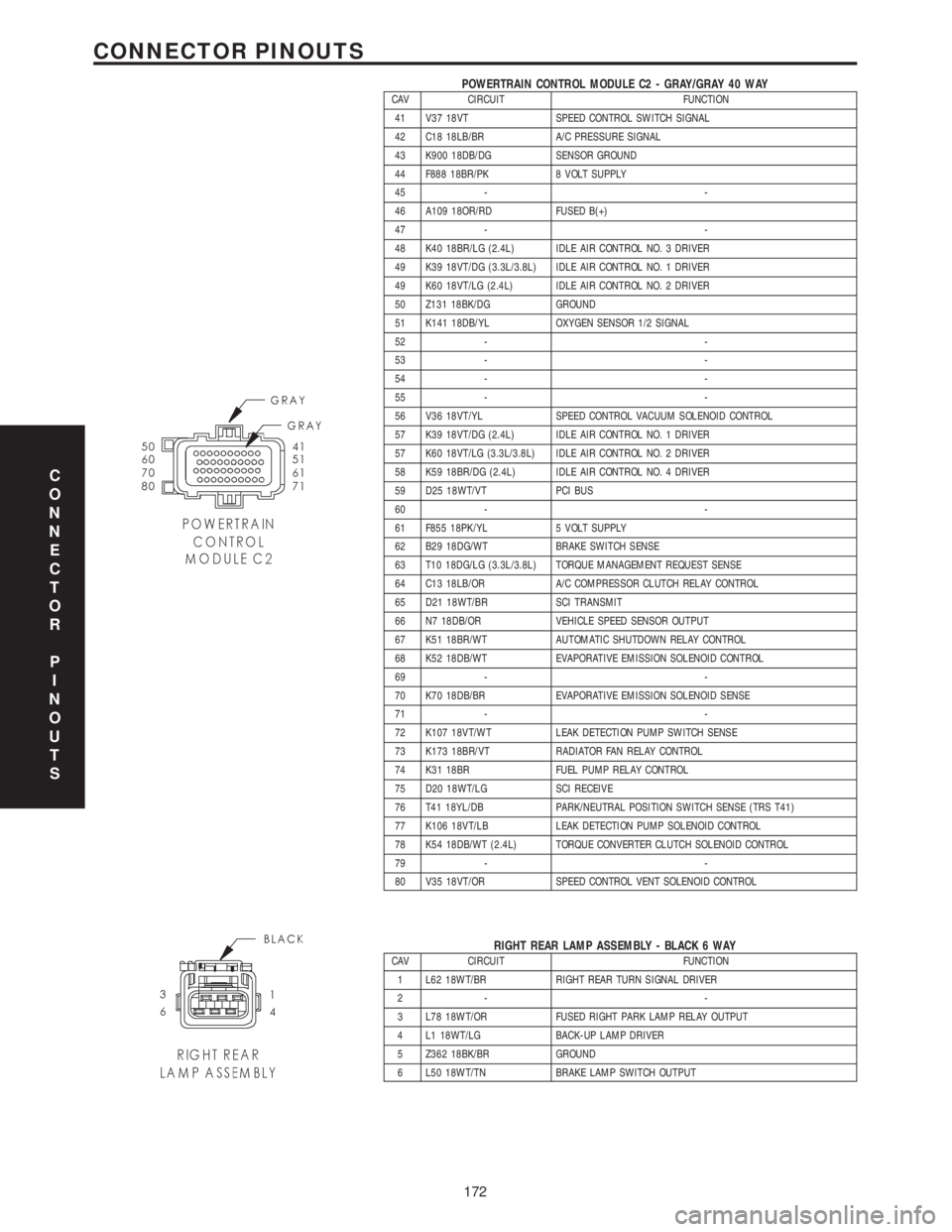
POWERTRAIN CONTROL MODULE C2 - GRAY/GRAY 40 WAYCAV CIRCUIT FUNCTION
41 V37 18VT SPEED CONTROL SWITCH SIGNAL
42 C18 18LB/BR A/C PRESSURE SIGNAL
43 K900 18DB/DG SENSOR GROUND
44 F888 18BR/PK 8 VOLT SUPPLY
45 - -
46 A109 18OR/RD FUSED B(+)
47 - -
48 K40 18BR/LG (2.4L) IDLE AIR CONTROL NO. 3 DRIVER
49 K39 18VT/DG (3.3L/3.8L) IDLE AIR CONTROL NO. 1 DRIVER
49 K60 18VT/LG (2.4L) IDLE AIR CONTROL NO. 2 DRIVER
50 Z131 18BK/DG GROUND
51 K141 18DB/YL OXYGEN SENSOR 1/2 SIGNAL
52 - -
53 - -
54 - -
55 - -
56 V36 18VT/YL SPEED CONTROL VACUUM SOLENOID CONTROL
57 K39 18VT/DG (2.4L) IDLE AIR CONTROL NO. 1 DRIVER
57 K60 18VT/LG (3.3L/3.8L) IDLE AIR CONTROL NO. 2 DRIVER
58 K59 18BR/DG (2.4L) IDLE AIR CONTROL NO. 4 DRIVER
59 D25 18WT/VT PCI BUS
60 - -
61 F855 18PK/YL 5 VOLT SUPPLY
62 B29 18DG/WT BRAKE SWITCH SENSE
63 T10 18DG/LG (3.3L/3.8L) TORQUE MANAGEMENT REQUEST SENSE
64 C13 18LB/OR A/C COMPRESSOR CLUTCH RELAY CONTROL
65 D21 18WT/BR SCI TRANSMIT
66 N7 18DB/OR VEHICLE SPEED SENSOR OUTPUT
67 K51 18BR/WT AUTOMATIC SHUTDOWN RELAY CONTROL
68 K52 18DB/WT EVAPORATIVE EMISSION SOLENOID CONTROL
69 - -
70 K70 18DB/BR EVAPORATIVE EMISSION SOLENOID SENSE
71 - -
72 K107 18VT/WT LEAK DETECTION PUMP SWITCH SENSE
73 K173 18BR/VT RADIATOR FAN RELAY CONTROL
74 K31 18BR FUEL PUMP RELAY CONTROL
75 D20 18WT/LG SCI RECEIVE
76 T41 18YL/DB PARK/NEUTRAL POSITION SWITCH SENSE (TRS T41)
77 K106 18VT/LB LEAK DETECTION PUMP SOLENOID CONTROL
78 K54 18DB/WT (2.4L) TORQUE CONVERTER CLUTCH SOLENOID CONTROL
79 - -
80 V35 18VT/OR SPEED CONTROL VENT SOLENOID CONTROL
RIGHT REAR LAMP ASSEMBLY - BLACK 6 WAYCAV CIRCUIT FUNCTION
1 L62 18WT/BR RIGHT REAR TURN SIGNAL DRIVER
2- -
3 L78 18WT/OR FUSED RIGHT PARK LAMP RELAY OUTPUT
4 L1 18WT/LG BACK-UP LAMP DRIVER
5 Z362 18BK/BR GROUND
6 L50 18WT/TN BRAKE LAMP SWITCH OUTPUT
C
O
N
N
E
C
T
O
R
P
I
N
O
U
T
S
172
CONNECTOR PINOUTS