2001 CHRYSLER VOYAGER engine
[x] Cancel search: enginePage 3909 of 4284
TEST ACTION APPLICABILITY
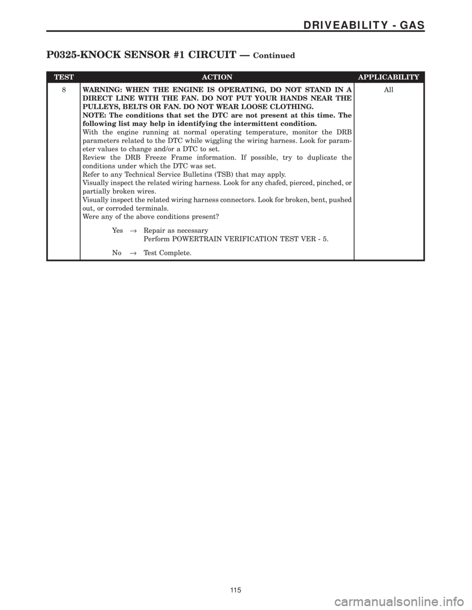
8WARNING: WHEN THE ENGINE IS OPERATING, DO NOT STAND IN A
DIRECT LINE WITH THE FAN. DO NOT PUT YOUR HANDS NEAR THE
PULLEYS, BELTS OR FAN. DO NOT WEAR LOOSE CLOTHING.
NOTE: The conditions that set the DTC are not present at this time. The
following list may help in identifying the intermittent condition.
With the engine running at normal operating temperature, monitor the DRB
parameters related to the DTC while wiggling the wiring harness. Look for param-
eter values to change and/or a DTC to set.
Review the DRB Freeze Frame information. If possible, try to duplicate the
conditions under which the DTC was set.
Refer to any Technical Service Bulletins (TSB) that may apply.
Visually inspect the related wiring harness. Look for any chafed, pierced, pinched, or
partially broken wires.
Visually inspect the related wiring harness connectors. Look for broken, bent, pushed
out, or corroded terminals.
Were any of the above conditions present?All
Ye s®Repair as necessary
Perform POWERTRAIN VERIFICATION TEST VER - 5.
No®Test Complete.
11 5
DRIVEABILITY - GAS
P0325-KNOCK SENSOR #1 CIRCUIT ÐContinued
Page 3910 of 4284
Symptom:
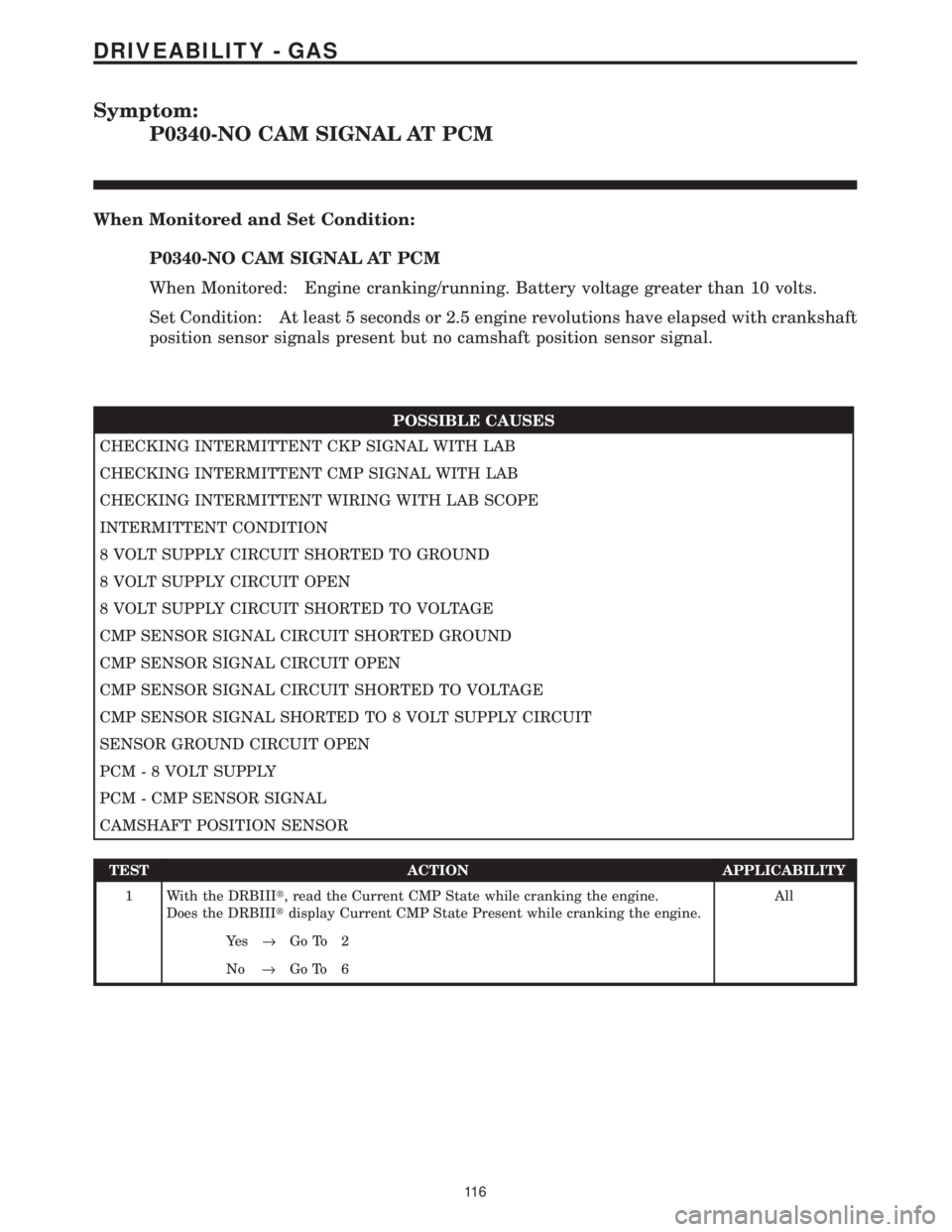
P0340-NO CAM SIGNAL AT PCM
When Monitored and Set Condition:
P0340-NO CAM SIGNAL AT PCM
When Monitored: Engine cranking/running. Battery voltage greater than 10 volts.
Set Condition: At least 5 seconds or 2.5 engine revolutions have elapsed with crankshaft
position sensor signals present but no camshaft position sensor signal.
POSSIBLE CAUSES
CHECKING INTERMITTENT CKP SIGNAL WITH LAB
CHECKING INTERMITTENT CMP SIGNAL WITH LAB
CHECKING INTERMITTENT WIRING WITH LAB SCOPE
INTERMITTENT CONDITION
8 VOLT SUPPLY CIRCUIT SHORTED TO GROUND
8 VOLT SUPPLY CIRCUIT OPEN
8 VOLT SUPPLY CIRCUIT SHORTED TO VOLTAGE
CMP SENSOR SIGNAL CIRCUIT SHORTED GROUND
CMP SENSOR SIGNAL CIRCUIT OPEN
CMP SENSOR SIGNAL CIRCUIT SHORTED TO VOLTAGE
CMP SENSOR SIGNAL SHORTED TO 8 VOLT SUPPLY CIRCUIT
SENSOR GROUND CIRCUIT OPEN
PCM - 8 VOLT SUPPLY
PCM - CMP SENSOR SIGNAL
CAMSHAFT POSITION SENSOR
TEST ACTION APPLICABILITY
1 With the DRBIIIt, read the Current CMP State while cranking the engine.
Does the DRBIIItdisplay Current CMP State Present while cranking the engine.All
Ye s®Go To 2
No®Go To 6
11 6
DRIVEABILITY - GAS
Page 3911 of 4284
TEST ACTION APPLICABILITY
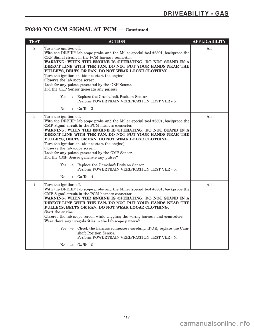
2 Turn the ignition off.
With the DRBIIItlab scope probe and the Miller special tool #6801, backprobe the
CKP Signal circuit in the PCM harness connector.
WARNING: WHEN THE ENGINE IS OPERATING, DO NOT STAND IN A
DIRECT LINE WITH THE FAN. DO NOT PUT YOUR HANDS NEAR THE
PULLEYS, BELTS OR FAN. DO NOT WEAR LOOSE CLOTHING.
Turn the ignition on. (do not start the engine)
Observe the lab scope screen.
Look for any pulses generated by the CKP Sensor.
Did the CKP Sensor generate any pulses?All
Ye s®Replace the Crankshaft Position Sensor.
Perform POWERTRAIN VERIFICATION TEST VER - 5.
No®Go To 3
3 Turn the ignition off.
With the DRBIIItlab scope probe and the Miller special tool #6801, backprobe the
CMP Signal circuit in the PCM harness connector.
WARNING: WHEN THE ENGINE IS OPERATING, DO NOT STAND IN A
DIRECT LINE WITH THE FAN. DO NOT PUT YOUR HANDS NEAR THE
PULLEYS, BELTS OR FAN. DO NOT WEAR LOOSE CLOTHING.
Turn the ignition on. (do not start the engine)
Observe the lab scope screen.
Look for any pulses generated by the CMP Sensor.
Did the CMP Sensor generate any pulses?All
Ye s®Replace the Camshaft Position Sensor.
Perform POWERTRAIN VERIFICATION TEST VER - 5.
No®Go To 4
4 Turn the ignition off.
With the DRBIIItlab scope probe and the Miller special tool #6801, backprobe the
CMP Signal circuit in the PCM harness connector.
WARNING: WHEN THE ENGINE IS OPERATING, DO NOT STAND IN A
DIRECT LINE WITH THE FAN. DO NOT PUT YOUR HANDS NEAR THE
PULLEYS, BELTS OR FAN. DO NOT WEAR LOOSE CLOTHING.
Start the engine.
Observe the lab scope screen while wiggling the wiring harness and connectors.
Were there any irregularities in the lab scope pattern?All
Ye s®Check the harness connectors carefully. If OK, replace the Cam-
shaft Position Sensor.
Perform POWERTRAIN VERIFICATION TEST VER - 5.
No®Go To 5
11 7
DRIVEABILITY - GAS
P0340-NO CAM SIGNAL AT PCM ÐContinued
Page 3912 of 4284
TEST ACTION APPLICABILITY
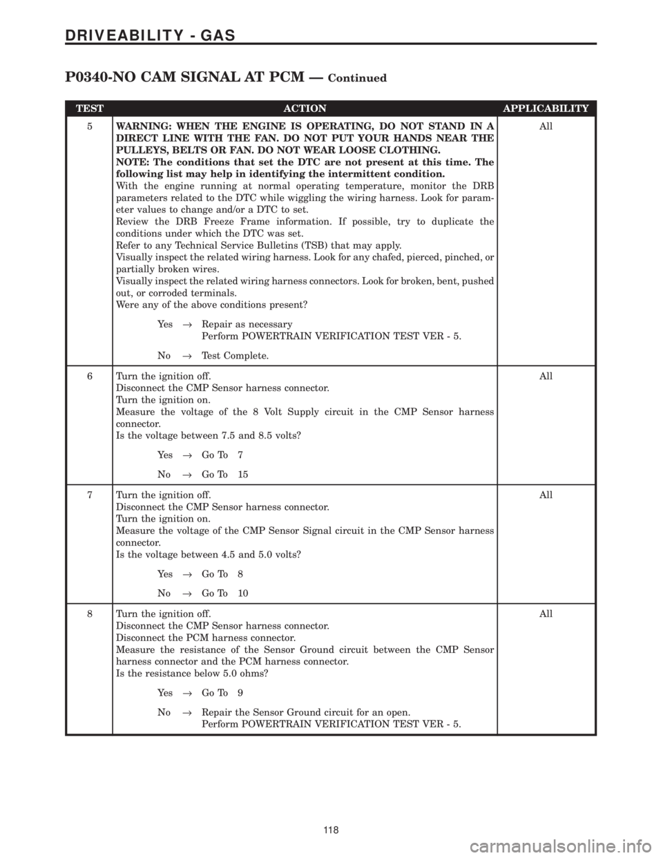
5WARNING: WHEN THE ENGINE IS OPERATING, DO NOT STAND IN A
DIRECT LINE WITH THE FAN. DO NOT PUT YOUR HANDS NEAR THE
PULLEYS, BELTS OR FAN. DO NOT WEAR LOOSE CLOTHING.
NOTE: The conditions that set the DTC are not present at this time. The
following list may help in identifying the intermittent condition.
With the engine running at normal operating temperature, monitor the DRB
parameters related to the DTC while wiggling the wiring harness. Look for param-
eter values to change and/or a DTC to set.
Review the DRB Freeze Frame information. If possible, try to duplicate the
conditions under which the DTC was set.
Refer to any Technical Service Bulletins (TSB) that may apply.
Visually inspect the related wiring harness. Look for any chafed, pierced, pinched, or
partially broken wires.
Visually inspect the related wiring harness connectors. Look for broken, bent, pushed
out, or corroded terminals.
Were any of the above conditions present?All
Ye s®Repair as necessary
Perform POWERTRAIN VERIFICATION TEST VER - 5.
No®Test Complete.
6 Turn the ignition off.
Disconnect the CMP Sensor harness connector.
Turn the ignition on.
Measure the voltage of the 8 Volt Supply circuit in the CMP Sensor harness
connector.
Is the voltage between 7.5 and 8.5 volts?All
Ye s®Go To 7
No®Go To 15
7 Turn the ignition off.
Disconnect the CMP Sensor harness connector.
Turn the ignition on.
Measure the voltage of the CMP Sensor Signal circuit in the CMP Sensor harness
connector.
Is the voltage between 4.5 and 5.0 volts?All
Ye s®Go To 8
No®Go To 10
8 Turn the ignition off.
Disconnect the CMP Sensor harness connector.
Disconnect the PCM harness connector.
Measure the resistance of the Sensor Ground circuit between the CMP Sensor
harness connector and the PCM harness connector.
Is the resistance below 5.0 ohms?All
Ye s®Go To 9
No®Repair the Sensor Ground circuit for an open.
Perform POWERTRAIN VERIFICATION TEST VER - 5.
11 8
DRIVEABILITY - GAS
P0340-NO CAM SIGNAL AT PCM ÐContinued
Page 3915 of 4284
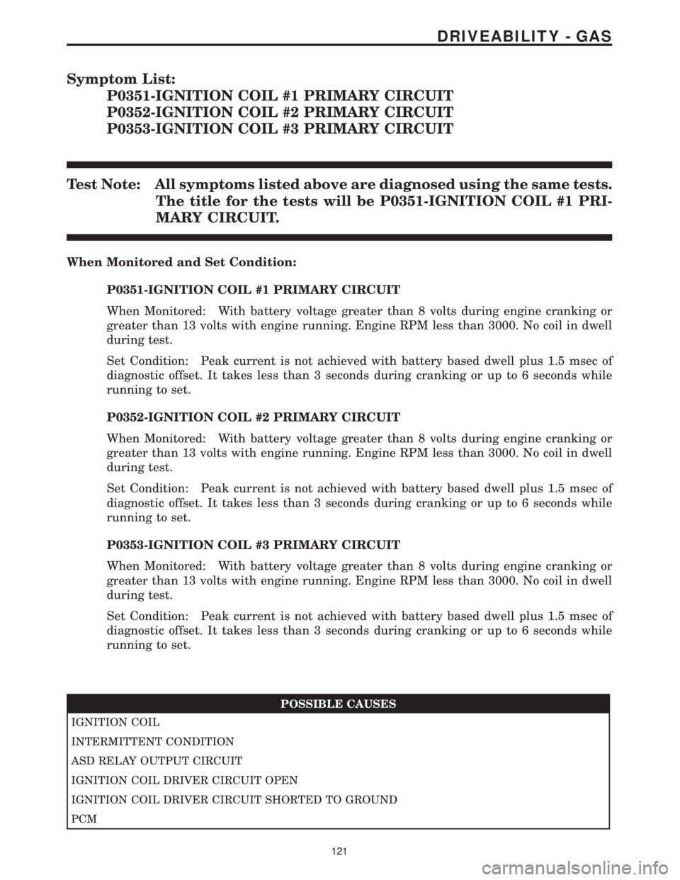
Symptom List:
P0351-IGNITION COIL #1 PRIMARY CIRCUIT
P0352-IGNITION COIL #2 PRIMARY CIRCUIT
P0353-IGNITION COIL #3 PRIMARY CIRCUIT
Test Note: All symptoms listed above are diagnosed using the same tests.
The title for the tests will be P0351-IGNITION COIL #1 PRI-
MARY CIRCUIT.
When Monitored and Set Condition:
P0351-IGNITION COIL #1 PRIMARY CIRCUIT
When Monitored: With battery voltage greater than 8 volts during engine cranking or
greater than 13 volts with engine running. Engine RPM less than 3000. No coil in dwell
during test.
Set Condition: Peak current is not achieved with battery based dwell plus 1.5 msec of
diagnostic offset. It takes less than 3 seconds during cranking or up to 6 seconds while
running to set.
P0352-IGNITION COIL #2 PRIMARY CIRCUIT
When Monitored: With battery voltage greater than 8 volts during engine cranking or
greater than 13 volts with engine running. Engine RPM less than 3000. No coil in dwell
during test.
Set Condition: Peak current is not achieved with battery based dwell plus 1.5 msec of
diagnostic offset. It takes less than 3 seconds during cranking or up to 6 seconds while
running to set.
P0353-IGNITION COIL #3 PRIMARY CIRCUIT
When Monitored: With battery voltage greater than 8 volts during engine cranking or
greater than 13 volts with engine running. Engine RPM less than 3000. No coil in dwell
during test.
Set Condition: Peak current is not achieved with battery based dwell plus 1.5 msec of
diagnostic offset. It takes less than 3 seconds during cranking or up to 6 seconds while
running to set.
POSSIBLE CAUSES
IGNITION COIL
INTERMITTENT CONDITION
ASD RELAY OUTPUT CIRCUIT
IGNITION COIL DRIVER CIRCUIT OPEN
IGNITION COIL DRIVER CIRCUIT SHORTED TO GROUND
PCM
121
DRIVEABILITY - GAS
Page 3916 of 4284
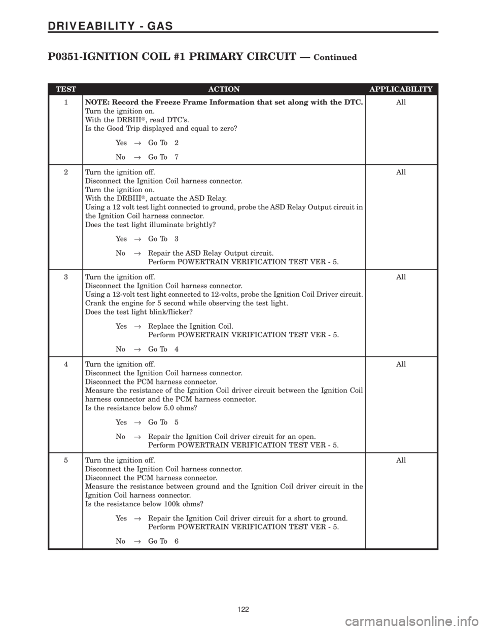
TEST ACTION APPLICABILITY
1NOTE: Record the Freeze Frame Information that set along with the DTC.
Turn the ignition on.
With the DRBIIIt, read DTC's.
Is the Good Trip displayed and equal to zero?All
Ye s®Go To 2
No®Go To 7
2 Turn the ignition off.
Disconnect the Ignition Coil harness connector.
Turn the ignition on.
With the DRBIIIt, actuate the ASD Relay.
Using a 12 volt test light connected to ground, probe the ASD Relay Output circuit in
the Ignition Coil harness connector.
Does the test light illuminate brightly?All
Ye s®Go To 3
No®Repair the ASD Relay Output circuit.
Perform POWERTRAIN VERIFICATION TEST VER - 5.
3 Turn the ignition off.
Disconnect the Ignition Coil harness connector.
Using a 12-volt test light connected to 12-volts, probe the Ignition Coil Driver circuit.
Crank the engine for 5 second while observing the test light.
Does the test light blink/flicker?All
Ye s®Replace the Ignition Coil.
Perform POWERTRAIN VERIFICATION TEST VER - 5.
No®Go To 4
4 Turn the ignition off.
Disconnect the Ignition Coil harness connector.
Disconnect the PCM harness connector.
Measure the resistance of the Ignition Coil driver circuit between the Ignition Coil
harness connector and the PCM harness connector.
Is the resistance below 5.0 ohms?All
Ye s®Go To 5
No®Repair the Ignition Coil driver circuit for an open.
Perform POWERTRAIN VERIFICATION TEST VER - 5.
5 Turn the ignition off.
Disconnect the Ignition Coil harness connector.
Disconnect the PCM harness connector.
Measure the resistance between ground and the Ignition Coil driver circuit in the
Ignition Coil harness connector.
Is the resistance below 100k ohms?All
Ye s®Repair the Ignition Coil driver circuit for a short to ground.
Perform POWERTRAIN VERIFICATION TEST VER - 5.
No®Go To 6
122
DRIVEABILITY - GAS
P0351-IGNITION COIL #1 PRIMARY CIRCUIT ÐContinued
Page 3917 of 4284
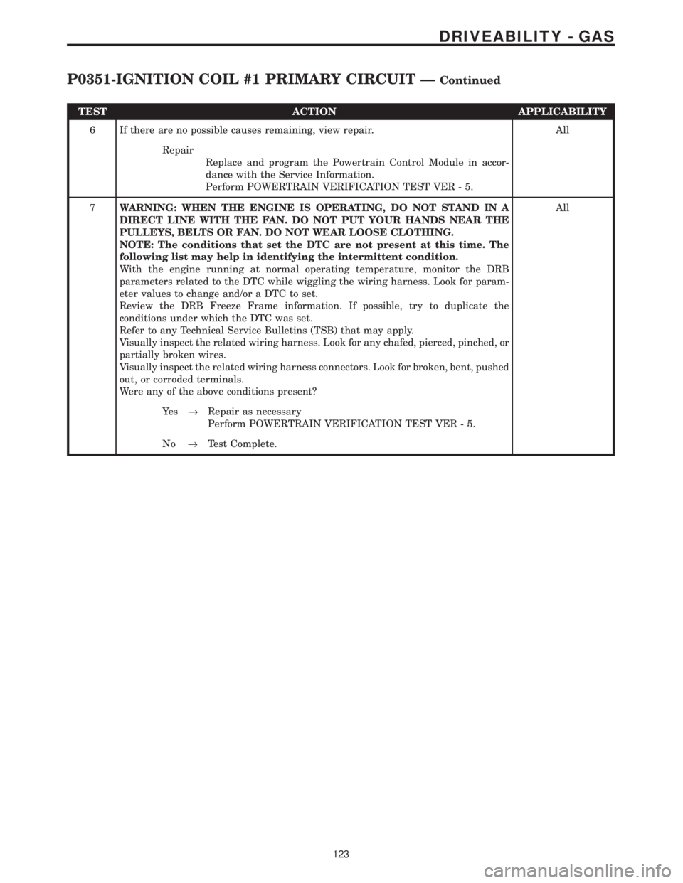
TEST ACTION APPLICABILITY
6 If there are no possible causes remaining, view repair. All
Repair
Replace and program the Powertrain Control Module in accor-
dance with the Service Information.
Perform POWERTRAIN VERIFICATION TEST VER - 5.
7WARNING: WHEN THE ENGINE IS OPERATING, DO NOT STAND IN A
DIRECT LINE WITH THE FAN. DO NOT PUT YOUR HANDS NEAR THE
PULLEYS, BELTS OR FAN. DO NOT WEAR LOOSE CLOTHING.
NOTE: The conditions that set the DTC are not present at this time. The
following list may help in identifying the intermittent condition.
With the engine running at normal operating temperature, monitor the DRB
parameters related to the DTC while wiggling the wiring harness. Look for param-
eter values to change and/or a DTC to set.
Review the DRB Freeze Frame information. If possible, try to duplicate the
conditions under which the DTC was set.
Refer to any Technical Service Bulletins (TSB) that may apply.
Visually inspect the related wiring harness. Look for any chafed, pierced, pinched, or
partially broken wires.
Visually inspect the related wiring harness connectors. Look for broken, bent, pushed
out, or corroded terminals.
Were any of the above conditions present?All
Ye s®Repair as necessary
Perform POWERTRAIN VERIFICATION TEST VER - 5.
No®Test Complete.
123
DRIVEABILITY - GAS
P0351-IGNITION COIL #1 PRIMARY CIRCUIT ÐContinued
Page 3918 of 4284
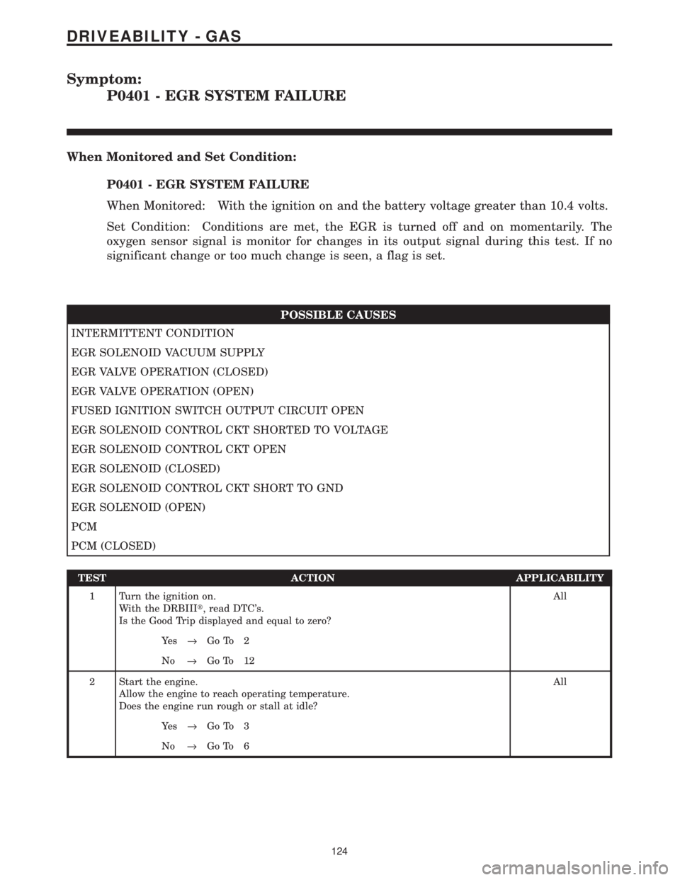
Symptom:
P0401 - EGR SYSTEM FAILURE
When Monitored and Set Condition:
P0401 - EGR SYSTEM FAILURE
When Monitored: With the ignition on and the battery voltage greater than 10.4 volts.
Set Condition: Conditions are met, the EGR is turned off and on momentarily. The
oxygen sensor signal is monitor for changes in its output signal during this test. If no
significant change or too much change is seen, a flag is set.
POSSIBLE CAUSES
INTERMITTENT CONDITION
EGR SOLENOID VACUUM SUPPLY
EGR VALVE OPERATION (CLOSED)
EGR VALVE OPERATION (OPEN)
FUSED IGNITION SWITCH OUTPUT CIRCUIT OPEN
EGR SOLENOID CONTROL CKT SHORTED TO VOLTAGE
EGR SOLENOID CONTROL CKT OPEN
EGR SOLENOID (CLOSED)
EGR SOLENOID CONTROL CKT SHORT TO GND
EGR SOLENOID (OPEN)
PCM
PCM (CLOSED)
TEST ACTION APPLICABILITY
1 Turn the ignition on.
With the DRBIIIt, read DTC's.
Is the Good Trip displayed and equal to zero?All
Ye s®Go To 2
No®Go To 12
2 Start the engine.
Allow the engine to reach operating temperature.
Does the engine run rough or stall at idle?All
Ye s®Go To 3
No®Go To 6
124
DRIVEABILITY - GAS