2001 CHRYSLER VOYAGER Engine
[x] Cancel search: EnginePage 3781 of 4284
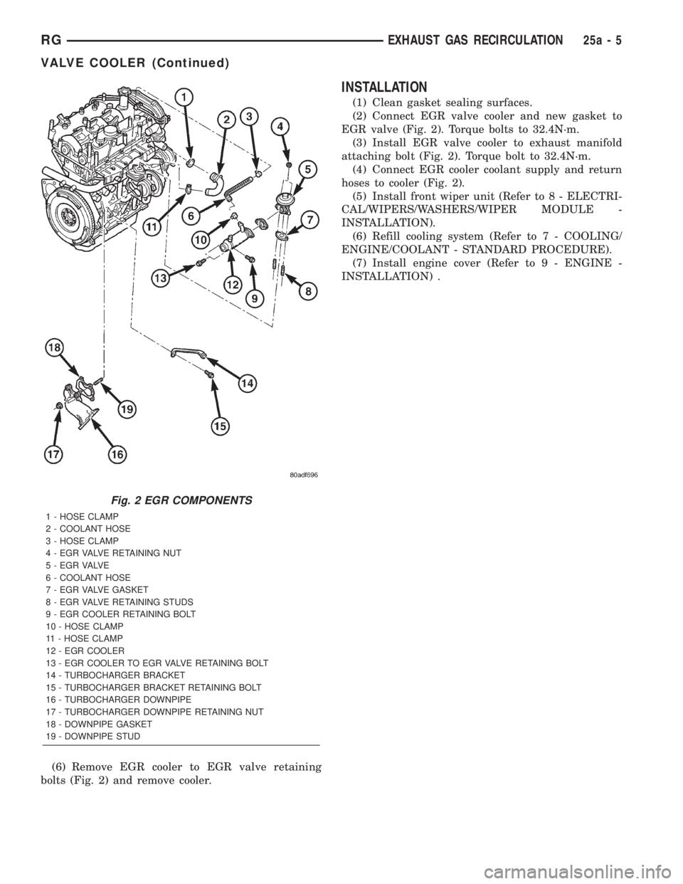
(6) Remove EGR cooler to EGR valve retaining
bolts (Fig. 2) and remove cooler.
INSTALLATION
(1) Clean gasket sealing surfaces.
(2) Connect EGR valve cooler and new gasket to
EGR valve (Fig. 2). Torque bolts to 32.4N´m.
(3) Install EGR valve cooler to exhaust manifold
attaching bolt (Fig. 2). Torque bolt to 32.4N´m.
(4) Connect EGR cooler coolant supply and return
hoses to cooler (Fig. 2).
(5) Install front wiper unit (Refer to 8 - ELECTRI-
CAL/WIPERS/WASHERS/WIPER MODULE -
INSTALLATION).
(6) Refill cooling system (Refer to 7 - COOLING/
ENGINE/COOLANT - STANDARD PROCEDURE).
(7) Install engine cover (Refer to 9 - ENGINE -
INSTALLATION) .
Fig. 2 EGR COMPONENTS
1 - HOSE CLAMP
2 - COOLANT HOSE
3 - HOSE CLAMP
4 - EGR VALVE RETAINING NUT
5 - E G R VA LV E
6 - COOLANT HOSE
7 - EGR VALVE GASKET
8 - EGR VALVE RETAINING STUDS
9 - EGR COOLER RETAINING BOLT
10 - HOSE CLAMP
11 - HOSE CLAMP
12 - EGR COOLER
13 - EGR COOLER TO EGR VALVE RETAINING BOLT
14 - TURBOCHARGER BRACKET
15 - TURBOCHARGER BRACKET RETAINING BOLT
16 - TURBOCHARGER DOWNPIPE
17 - TURBOCHARGER DOWNPIPE RETAINING NUT
18 - DOWNPIPE GASKET
19 - DOWNPIPE STUD
RGEXHAUST GAS RECIRCULATION25a-5
VALVE COOLER (Continued)
Page 3782 of 4284
ON-BOARD DIAGNOSTICS
TABLE OF CONTENTS
page
ON-BOARD DIAGNOSTICS
DESCRIPTION............................6
ON-BOARD DIAGNOSTICS
DESCRIPTION - DIAGNOSTIC TROUBLE CODES
On the following pages, a list of DTC's is provided
for the 2.5L diesel engine. A DTC indicates that the
ECM has recognized an abnormal signal in a circuit
or the system. A DTC may indicate the result of a
failure, but most likely will not identify the failed
component directly. Refer to the appropriate diagnos-
tic manual for more information on diagnosis of trou-
ble codes.
ACCESSING DIAGNOSTIC TROUBLE CODES
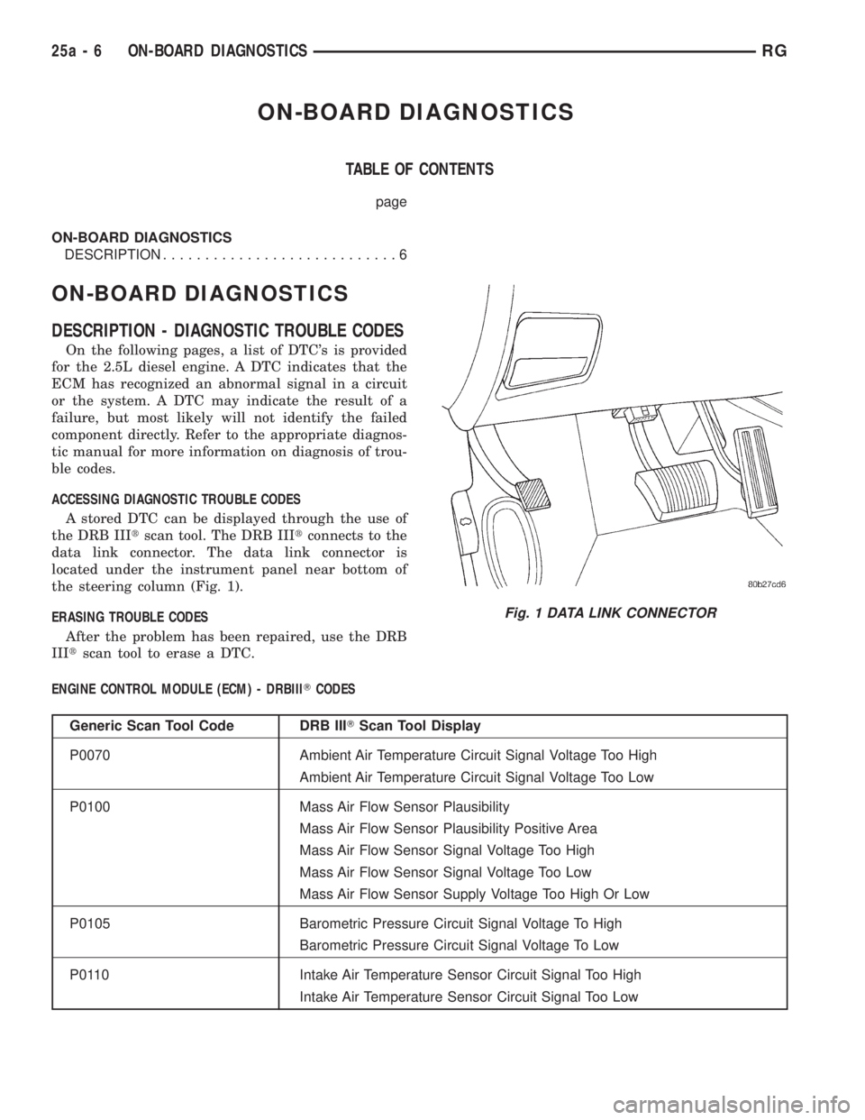
A stored DTC can be displayed through the use of
the DRB IIItscan tool. The DRB IIItconnects to the
data link connector. The data link connector is
located under the instrument panel near bottom of
the steering column (Fig. 1).
ERASING TROUBLE CODES
After the problem has been repaired, use the DRB
IIItscan tool to erase a DTC.
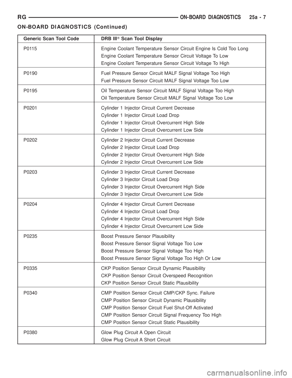
ENGINE CONTROL MODULE (ECM) - DRBIIITCODES
Generic Scan Tool Code DRB IIITScan Tool Display
P0070 Ambient Air Temperature Circuit Signal Voltage Too High
Ambient Air Temperature Circuit Signal Voltage Too Low
P0100 Mass Air Flow Sensor Plausibility
Mass Air Flow Sensor Plausibility Positive Area
Mass Air Flow Sensor Signal Voltage Too High
Mass Air Flow Sensor Signal Voltage Too Low
Mass Air Flow Sensor Supply Voltage Too High Or Low
P0105 Barometric Pressure Circuit Signal Voltage To High
Barometric Pressure Circuit Signal Voltage To Low
P0110 Intake Air Temperature Sensor Circuit Signal Too High
Intake Air Temperature Sensor Circuit Signal Too Low
Fig. 1 DATA LINK CONNECTOR
25a - 6 ON-BOARD DIAGNOSTICSRG
Page 3783 of 4284
Generic Scan Tool Code DRB IIITScan Tool Display
P0115 Engine Coolant Temperature Sensor Circuit Engine Is Cold Too Long
Engine Coolant Temperature Sensor Circuit Voltage To Low
Engine Coolant Temperature Sensor Circuit Voltage To High
P0190 Fuel Pressure Sensor Circuit MALF Signal Voltage Too High
Fuel Pressure Sensor Circuit MALF Signal Voltage Too Low
P0195 Oil Temperature Sensor Circuit MALF Signal Voltage Too High
Oil Temperature Sensor Circuit MALF Signal Voltage Too Low
P0201 Cylinder 1 Injector Circuit Current Decrease
Cylinder 1 Injector Circuit Load Drop
Cylinder 1 Injector Circuit Overcurrent High Side
Cylinder 1 Injector Circuit Overcurrent Low Side
P0202 Cylinder 2 Injector Circuit Current Decrease
Cylinder 2 Injector Circuit Load Drop
Cylinder 2 Injector Circuit Overcurrent High Side
Cylinder 2 Injector Circuit Overcurrent Low Side
P0203 Cylinder 3 Injector Circuit Current Decrease
Cylinder 3 Injector Circuit Load Drop
Cylinder 3 Injector Circuit Overcurrent High Side
Cylinder 3 Injector Circuit Overcurrent Low Side
P0204 Cylinder 4 Injector Circuit Current Decrease
Cylinder 4 Injector Circuit Load Drop
Cylinder 4 Injector Circuit Overcurrent High Side
Cylinder 4 Injector Circuit Overcurrent Low Side
P0235 Boost Pressure Sensor Plausibility
Boost Pressure Sensor Signal Voltage Too Low
Boost Pressure Sensor Signal Voltage Too High
Boost Pressure Sensor Signal Voltage Too High Or Low
P0335 CKP Position Sensor Circuit Dynamic Plausibility
CKP Position Sensor Circuit Overspeed Recognition
CKP Position Sensor Circuit Static Plausibility
P0340 CMP Position Sensor Circuit CMP/CKP Sync. Failure
CMP Position Sensor Circuit Dynamic Plausibility
CMP Position Sensor Circuit Fuel Shut-Off Activated
CMP Position Sensor Circuit Signal Frequency Too High
CMP Position Sensor Circuit Static Plausibility
P0380 Glow Plug Circuit A Open Circuit
Glow Plug Circuit A Short Circuit
RGON-BOARD DIAGNOSTICS25a-7
ON-BOARD DIAGNOSTICS (Continued)
Page 3791 of 4284
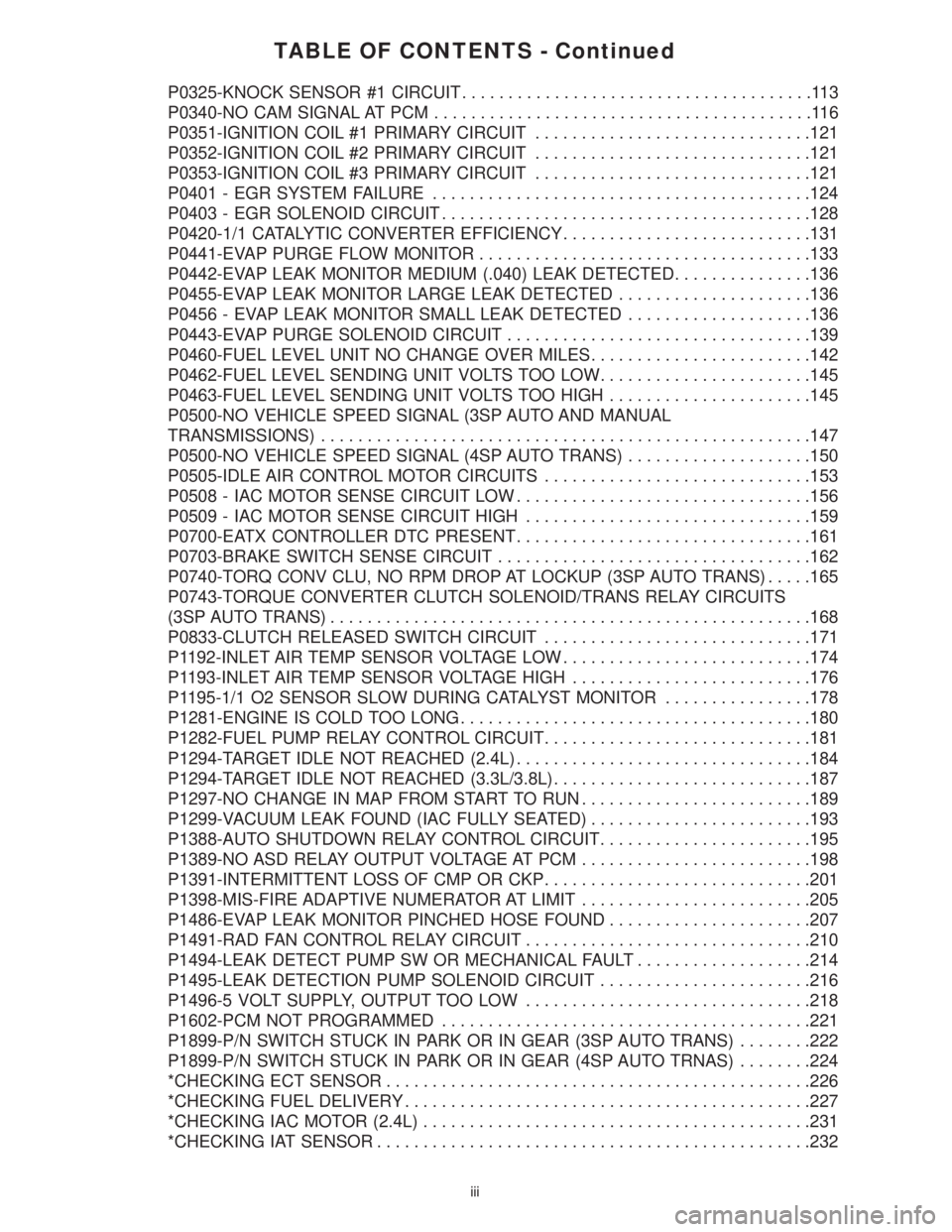
TABLE OF CONTENTS - Continued
P0325-KNOCK SENSOR #1 CIRCUIT......................................113
P0340-NO CAM SIGNAL AT PCM.........................................116
P0351-IGNITION COIL #1 PRIMARY CIRCUIT..............................121
P0352-IGNITION COIL #2 PRIMARY CIRCUIT..............................121
P0353-IGNITION COIL #3 PRIMARY CIRCUIT..............................121
P0401 - EGR SYSTEM FAILURE.........................................124
P0403 - EGR SOLENOID CIRCUIT........................................128
P0420-1/1 CATALYTIC CONVERTER EFFICIENCY...........................131
P0441-EVAP PURGE FLOW MONITOR....................................133
P0442-EVAP LEAK MONITOR MEDIUM (.040) LEAK DETECTED...............136
P0455-EVAP LEAK MONITOR LARGE LEAK DETECTED.....................136
P0456 - EVAP LEAK MONITOR SMALL LEAK DETECTED....................136
P0443-EVAP PURGE SOLENOID CIRCUIT.................................139
P0460-FUEL LEVEL UNIT NO CHANGE OVER MILES........................142
P0462-FUEL LEVEL SENDING UNIT VOLTS TOO LOW.......................145
P0463-FUEL LEVEL SENDING UNIT VOLTS TOO HIGH......................145
P0500-NO VEHICLE SPEED SIGNAL (3SP AUTO AND MANUAL
TRANSMISSIONS).....................................................147
P0500-NO VEHICLE SPEED SIGNAL (4SP AUTO TRANS)....................150
P0505-IDLE AIR CONTROL MOTOR CIRCUITS.............................153
P0508 - IAC MOTOR SENSE CIRCUIT LOW................................156
P0509 - IAC MOTOR SENSE CIRCUIT HIGH...............................159
P0700-EATX CONTROLLER DTC PRESENT................................161
P0703-BRAKE SWITCH SENSE CIRCUIT..................................162
P0740-TORQ CONV CLU, NO RPM DROP AT LOCKUP (3SP AUTO TRANS).....165
P0743-TORQUE CONVERTER CLUTCH SOLENOID/TRANS RELAY CIRCUITS
(3SP AUTO TRANS)....................................................168
P0833-CLUTCH RELEASED SWITCH CIRCUIT.............................171
P1192-INLET AIR TEMP SENSOR VOLTAGE LOW...........................174
P1193-INLET AIR TEMP SENSOR VOLTAGE HIGH..........................176
P1195-1/1 O2 SENSOR SLOW DURING CATALYST MONITOR................178
P1281-ENGINE IS COLD TOO LONG......................................180
P1282-FUEL PUMP RELAY CONTROL CIRCUIT.............................181
P1294-TARGET IDLE NOT REACHED (2.4L)................................184
P1294-TARGET IDLE NOT REACHED (3.3L/3.8L)............................187
P1297-NO CHANGE IN MAP FROM START TO RUN.........................189
P1299-VACUUM LEAK FOUND (IAC FULLY SEATED)........................193
P1388-AUTO SHUTDOWN RELAY CONTROL CIRCUIT.......................195
P1389-NO ASD RELAY OUTPUT VOLTAGE AT PCM.........................198
P1391-INTERMITTENT LOSS OF CMP OR CKP.............................201
P1398-MIS-FIRE ADAPTIVE NUMERATOR AT LIMIT.........................205
P1486-EVAP LEAK MONITOR PINCHED HOSE FOUND......................207
P1491-RAD FAN CONTROL RELAY CIRCUIT...............................210
P1494-LEAK DETECT PUMP SW OR MECHANICAL FAULT...................214
P1495-LEAK DETECTION PUMP SOLENOID CIRCUIT.......................216
P1496-5 VOLT SUPPLY, OUTPUT TOO LOW...............................218
P1602-PCM NOT PROGRAMMED........................................221
P1899-P/N SWITCH STUCK IN PARK OR IN GEAR (3SP AUTO TRANS)........222
P1899-P/N SWITCH STUCK IN PARK OR IN GEAR (4SP AUTO TRNAS)........224
*CHECKING ECT SENSOR..............................................226
*CHECKING FUEL DELIVERY............................................227
*CHECKING IAC MOTOR (2.4L)..........................................231
*CHECKING IAT SENSOR...............................................232
iii
Page 3792 of 4284
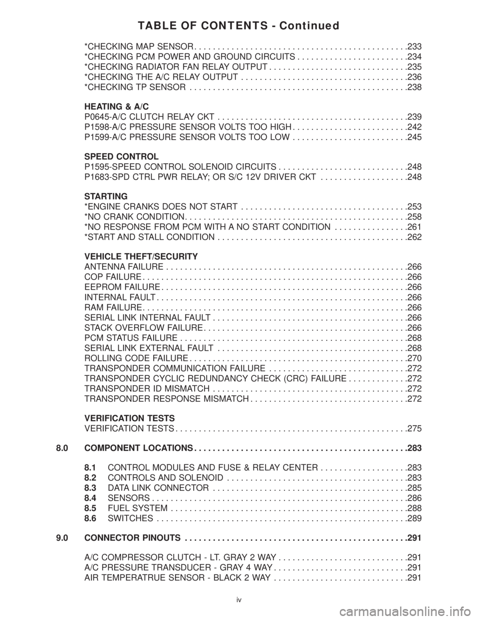
TABLE OF CONTENTS - Continued
*CHECKING MAP SENSOR..............................................233
*CHECKING PCM POWER AND GROUND CIRCUITS........................234
*CHECKING RADIATOR FAN RELAY OUTPUT..............................235
*CHECKING THE A/C RELAY OUTPUT....................................236
*CHECKING TP SENSOR...............................................238
HEATING & A/C
P0645-A/C CLUTCH RELAY CKT.........................................239
P1598-A/C PRESSURE SENSOR VOLTS TOO HIGH.........................242
P1599-A/C PRESSURE SENSOR VOLTS TOO LOW.........................245
SPEED CONTROL
P1595-SPEED CONTROL SOLENOID CIRCUITS............................248
P1683-SPD CTRL PWR RELAY; OR S/C 12V DRIVER CKT...................248
STARTING
*ENGINE CRANKS DOES NOT START....................................253
*NO CRANK CONDITION................................................258
*NO RESPONSE FROM PCM WITH A NO START CONDITION................261
*START AND STALL CONDITION.........................................262
VEHICLE THEFT/SECURITY
ANTENNA FAILURE....................................................266
COP FAILURE.........................................................266
EEPROM FAILURE.....................................................266
INTERNAL FAULT......................................................266
RAM FAILURE.........................................................266
SERIAL LINK INTERNAL FAULT..........................................266
STACK OVERFLOW FAILURE............................................266
PCM STATUS FAILURE.................................................268
SERIAL LINK EXTERNAL FAULT.........................................268
ROLLING CODE FAILURE...............................................270
TRANSPONDER COMMUNICATION FAILURE..............................272
TRANSPONDER CYCLIC REDUNDANCY CHECK (CRC) FAILURE.............272
TRANSPONDER ID MISMATCH..........................................272
TRANSPONDER RESPONSE MISMATCH..................................272
VERIFICATION TESTS
VERIFICATION TESTS..................................................275
8.0 COMPONENT LOCATIONS..............................................283
8.1CONTROL MODULES AND FUSE & RELAY CENTER...................283
8.2CONTROLS AND SOLENOID.......................................283
8.3DATA LINK CONNECTOR..........................................285
8.4SENSORS.......................................................286
8.5FUEL SYSTEM...................................................288
8.6SWITCHES......................................................289
9.0 CONNECTOR PINOUTS................................................291
A/C COMPRESSOR CLUTCH - LT. GRAY 2 WAY............................291
A/C PRESSURE TRANSDUCER - GRAY 4 WAY.............................291
AIR TEMPERATRUE SENSOR - BLACK 2 WAY.............................291
iv
Page 3793 of 4284
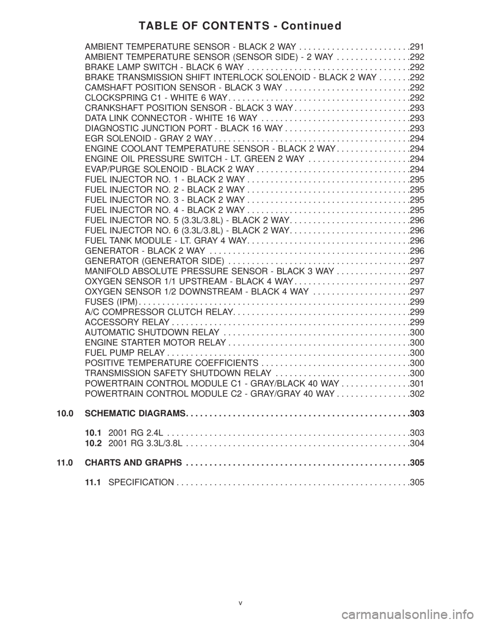
TABLE OF CONTENTS - Continued
AMBIENT TEMPERATURE SENSOR - BLACK 2 WAY........................291
AMBIENT TEMPERATURE SENSOR (SENSOR SIDE)-2WAY................292
BRAKE LAMP SWITCH - BLACK 6 WAY...................................292
BRAKE TRANSMISSION SHIFT INTERLOCK SOLENOID - BLACK 2 WAY.......292
CAMSHAFT POSITION SENSOR - BLACK 3 WAY...........................292
CLOCKSPRING C1 - WHITE 6 WAY.......................................292
CRANKSHAFT POSITION SENSOR - BLACK 3 WAY.........................293
DATA LINK CONNECTOR - WHITE 16 WAY................................293
DIAGNOSTIC JUNCTION PORT - BLACK 16 WAY...........................293
EGR SOLENOID - GRAY 2 WAY..........................................294
ENGINE COOLANT TEMPERATURE SENSOR - BLACK 2 WAY................294
ENGINE OIL PRESSURE SWITCH - LT. GREEN 2 WAY......................294
EVAP/PURGE SOLENOID - BLACK 2 WAY.................................294
FUEL INJECTOR NO. 1 - BLACK 2 WAY...................................295
FUEL INJECTOR NO. 2 - BLACK 2 WAY...................................295
FUEL INJECTOR NO. 3 - BLACK 2 WAY...................................295
FUEL INJECTOR NO. 4 - BLACK 2 WAY...................................295
FUEL INJECTOR NO. 5 (3.3L/3.8L) - BLACK 2 WAY..........................296
FUEL INJECTOR NO. 6 (3.3L/3.8L) - BLACK 2 WAY..........................296
FUEL TANK MODULE - LT. GRAY 4 WAY...................................296
GENERATOR - BLACK 2 WAY...........................................296
GENERATOR (GENERATOR SIDE).......................................297
MANIFOLD ABSOLUTE PRESSURE SENSOR - BLACK 3 WAY................297
OXYGEN SENSOR 1/1 UPSTREAM - BLACK 4 WAY.........................297
OXYGEN SENSOR 1/2 DOWNSTREAM - BLACK 4 WAY.....................297
FUSES (IPM)..........................................................299
A/C COMPRESSOR CLUTCH RELAY......................................299
ACCESSORY RELAY...................................................299
AUTOMATIC SHUTDOWN RELAY........................................300
ENGINE STARTER MOTOR RELAY.......................................300
FUEL PUMP RELAY....................................................300
POSITIVE TEMPERATURE COEFFICIENTS................................300
TRANSMISSION SAFETY SHUTDOWN RELAY.............................300
POWERTRAIN CONTROL MODULE C1 - GRAY/BLACK 40 WAY...............301
POWERTRAIN CONTROL MODULE C2 - GRAY/GRAY 40 WAY................302
10.0 SCHEMATIC DIAGRAMS................................................303
10.12001 RG 2.4L....................................................303
10.22001 RG 3.3L/3.8L................................................304
11.0 CHARTS AND GRAPHS................................................305
11.1SPECIFICATION..................................................305
v
Page 3795 of 4284
1.0 INTRODUCTION
The procedures contained in this manual include
specifications, instructions, and graphics needed to
diagnose the PCM Powertrain System. The diag-
nostics in this manual are based on the failure
condition or symptom being present at time of
diagnosis.
Please follow the recommendations below when
choosing your diagnostic path.
1. First make sure the DRBIIItis communicating
with the appropriate modules; ie., if the DRBIIIt
displays a No Response condition, you must
diagnose this first before proceeding.
2. Read DTC's (diagnostic trouble codes) with the
DRBIIIt.
3. If no DTC's are present, identify the customer
complaint.
4. Once the DTC or customer complaint is identi-
fied, locate the matching test in the Table of
Contents and begin to diagnose the symptom.
All component location views are in Section 8.0.
All connector pinouts are in Section 9.0. All system
schematics are in Section 10.0.
An * placed before the symptom description indi-
cates a customer complaint.
When repairs are required, refer to the appropri-
ate service information for the proper removal and
repair procedure.
Diagnostic procedures change every year. New
diagnostic systems may be added; carryover sys-
tems may be enhanced. READ THIS DIAGNOSTIC
INFORMATION BEFORE TRYING TO DIAG-
NOSE A VEHICLE CODE. It is recommended that
you review the entire diagnostic information to
become familiar with all new and changed diagnos-
tic procedures.
If you have any comments or recommendations
after reviewing the diagnostic information, please
fill out the form at the back of the book and mail it
back to us.
1.1 SYSTEM COVERAGE
This diagnostic procedures manual covers the
following 2001 Town and Country; Caravan/Grand
Caravan; and Voyager/Grand Voyager vehicles
equipped with the 2.4L and the 3.3L/3.8L engines.
1.2 SIX-STEP TROUBLESHOOTING
PROCEDURE
Diagnosis of the powertrain control module
(PCM) is done in six basic steps:
²verification of complaint
²verification of any related symptoms
²symptom analysis
²problem isolation
²repair of isolated problem
²verification of proper operation
2.0 IDENTIFICATION OF
SYSTEM
The Powertrain Control Module (PCM) monitors
and controls:
²Fuel System
²Idle Air Control System
²Ignition System
²Charging System
²Speed Control System
²Cooling system
3.0 SYSTEM DESCRIPTION AND
FUNCTIONAL OPERATION
3.1 GENERAL DESCRIPTION
These Sequential Fuel Injection (SFI) engine sys-
tems have the latest in technical advances. The
on-board Euro Stage III OBD diagnostics incorpo-
rated with the Powertrain Control Module (PCM)
are intended to assist the field technician in repair-
ing vehicle problems by the quickest means.
3.2 FUNCTIONAL OPERATION
3.2.1 FUEL CONTROL
The PCM controls the air/fuel ratio of the engine
by varying fuel injector on time. Mass air flow is
calculated using the speed density method using
enigne speed, manifold absolute pressure, and air
temperature change.
Different fuel calculation strategies are used de-
pending on the operational state of the engine.
During crank mode, a prime shot fuel pulse is
delivered followed by fuel pulses determined by a
crank time strategy. Cold engine operation is deter-
mined via an open loop strategy until the O2
sensors have reached operating temperature. At
this point, the strategy enters a closed loop mode
where fuel requirements are based upon the state of
the O2 sensors, engine speed, MAP, throttle posi-
tion, air temperature, battery voltage, and coolant
temperature.
1
GENERAL INFORMATION
Page 3796 of 4284
3.2.2 ON-BOARD DIAGNOSTICS
The PCM has been programmed to monitor many
different circuits of the fuel injection system. This
monitoring is called on-board diagnosis.
Certain criteria, or arming conditions, must be
met for a trouble code to be entered into the PCM
memory. The criteria may be a range of: engine rpm,
engine temperature, and/or input voltage to the
PCM. If a problem is sensed with a monitored
circuit, and all of the criteria or arming conditions
are met, then a trouble code will be stored in the
PCM.
It is possible that a trouble code for a monitored
circuit may not be entered into the PCM memory
even though a malfunction has occurred. This may
happen because one of the trouble code criteria have
not been met.The PCM compares input signal voltages from
each input device with specifications (the estab-
lished high and low limits of the range) that are
programmed into it for that device. If the input
voltage is not within specifications and other trou-
ble code criteria are met, a trouble code will be
stored in the PCM memory.
The On Board Diagnostics have evolved to the
second Generation of Diagnostics referred to as
Euro Stage III OBD.
The following table summarizes the various
Euro Stage III OBD monitors operation.
2
GENERAL INFORMATION