Page 209 of 4284
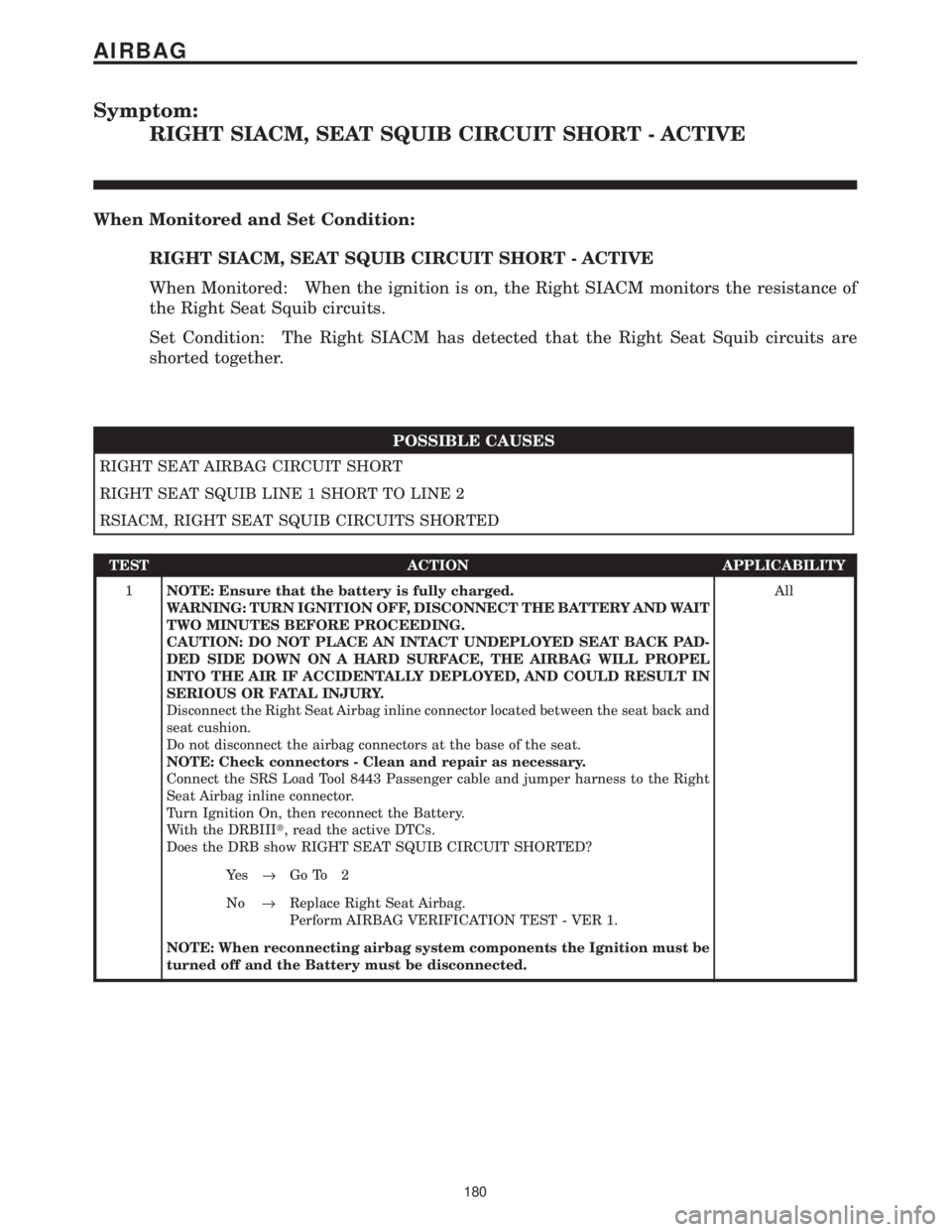
Symptom:
RIGHT SIACM, SEAT SQUIB CIRCUIT SHORT - ACTIVE
When Monitored and Set Condition:
RIGHT SIACM, SEAT SQUIB CIRCUIT SHORT - ACTIVE
When Monitored: When the ignition is on, the Right SIACM monitors the resistance of
the Right Seat Squib circuits.
Set Condition: The Right SIACM has detected that the Right Seat Squib circuits are
shorted together.
POSSIBLE CAUSES
RIGHT SEAT AIRBAG CIRCUIT SHORT
RIGHT SEAT SQUIB LINE 1 SHORT TO LINE 2
RSIACM, RIGHT SEAT SQUIB CIRCUITS SHORTED
TEST ACTION APPLICABILITY
1NOTE: Ensure that the battery is fully charged.
WARNING: TURN IGNITION OFF, DISCONNECT THE BATTERY AND WAIT
TWO MINUTES BEFORE PROCEEDING.
CAUTION: DO NOT PLACE AN INTACT UNDEPLOYED SEAT BACK PAD-
DED SIDE DOWN ON A HARD SURFACE, THE AIRBAG WILL PROPEL
INTO THE AIR IF ACCIDENTALLY DEPLOYED, AND COULD RESULT IN
SERIOUS OR FATAL INJURY.
Disconnect the Right Seat Airbag inline connector located between the seat back and
seat cushion.
Do not disconnect the airbag connectors at the base of the seat.
NOTE: Check connectors - Clean and repair as necessary.
Connect the SRS Load Tool 8443 Passenger cable and jumper harness to the Right
Seat Airbag inline connector.
Turn Ignition On, then reconnect the Battery.
With the DRBIIIt, read the active DTCs.
Does the DRB show RIGHT SEAT SQUIB CIRCUIT SHORTED?All
Ye s®Go To 2
No®Replace Right Seat Airbag.
Perform AIRBAG VERIFICATION TEST - VER 1.
NOTE: When reconnecting airbag system components the Ignition must be
turned off and the Battery must be disconnected.
180
AIRBAG
Page 211 of 4284
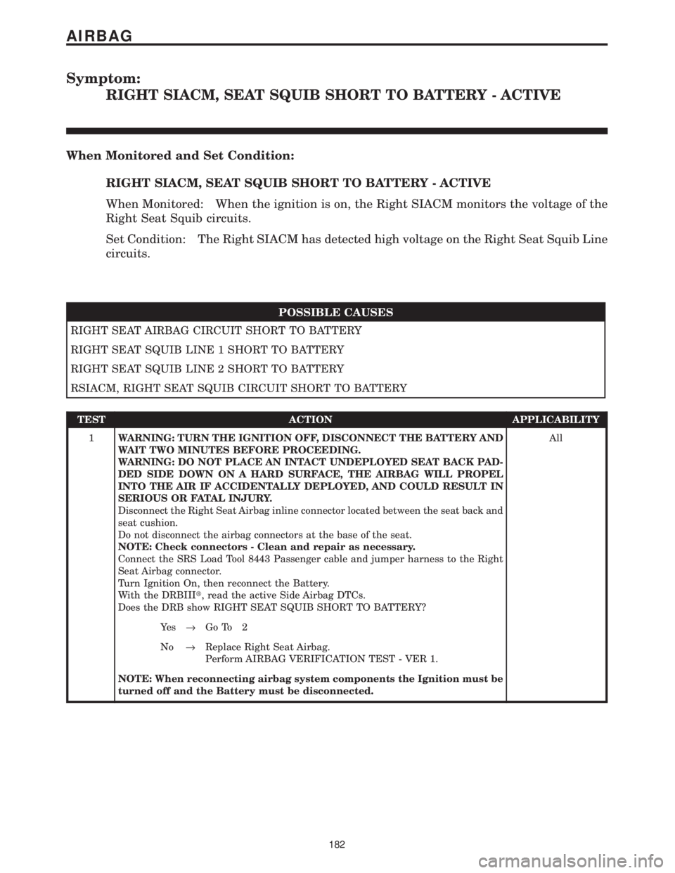
Symptom:
RIGHT SIACM, SEAT SQUIB SHORT TO BATTERY - ACTIVE
When Monitored and Set Condition:
RIGHT SIACM, SEAT SQUIB SHORT TO BATTERY - ACTIVE
When Monitored: When the ignition is on, the Right SIACM monitors the voltage of the
Right Seat Squib circuits.
Set Condition: The Right SIACM has detected high voltage on the Right Seat Squib Line
circuits.
POSSIBLE CAUSES
RIGHT SEAT AIRBAG CIRCUIT SHORT TO BATTERY
RIGHT SEAT SQUIB LINE 1 SHORT TO BATTERY
RIGHT SEAT SQUIB LINE 2 SHORT TO BATTERY
RSIACM, RIGHT SEAT SQUIB CIRCUIT SHORT TO BATTERY
TEST ACTION APPLICABILITY
1WARNING: TURN THE IGNITION OFF, DISCONNECT THE BATTERY AND
WAIT TWO MINUTES BEFORE PROCEEDING.
WARNING: DO NOT PLACE AN INTACT UNDEPLOYED SEAT BACK PAD-
DED SIDE DOWN ON A HARD SURFACE, THE AIRBAG WILL PROPEL
INTO THE AIR IF ACCIDENTALLY DEPLOYED, AND COULD RESULT IN
SERIOUS OR FATAL INJURY.
Disconnect the Right Seat Airbag inline connector located between the seat back and
seat cushion.
Do not disconnect the airbag connectors at the base of the seat.
NOTE: Check connectors - Clean and repair as necessary.
Connect the SRS Load Tool 8443 Passenger cable and jumper harness to the Right
Seat Airbag connector.
Turn Ignition On, then reconnect the Battery.
With the DRBIIIt, read the active Side Airbag DTCs.
Does the DRB show RIGHT SEAT SQUIB SHORT TO BATTERY?All
Ye s®Go To 2
No®Replace Right Seat Airbag.
Perform AIRBAG VERIFICATION TEST - VER 1.
NOTE: When reconnecting airbag system components the Ignition must be
turned off and the Battery must be disconnected.
182
AIRBAG
Page 214 of 4284
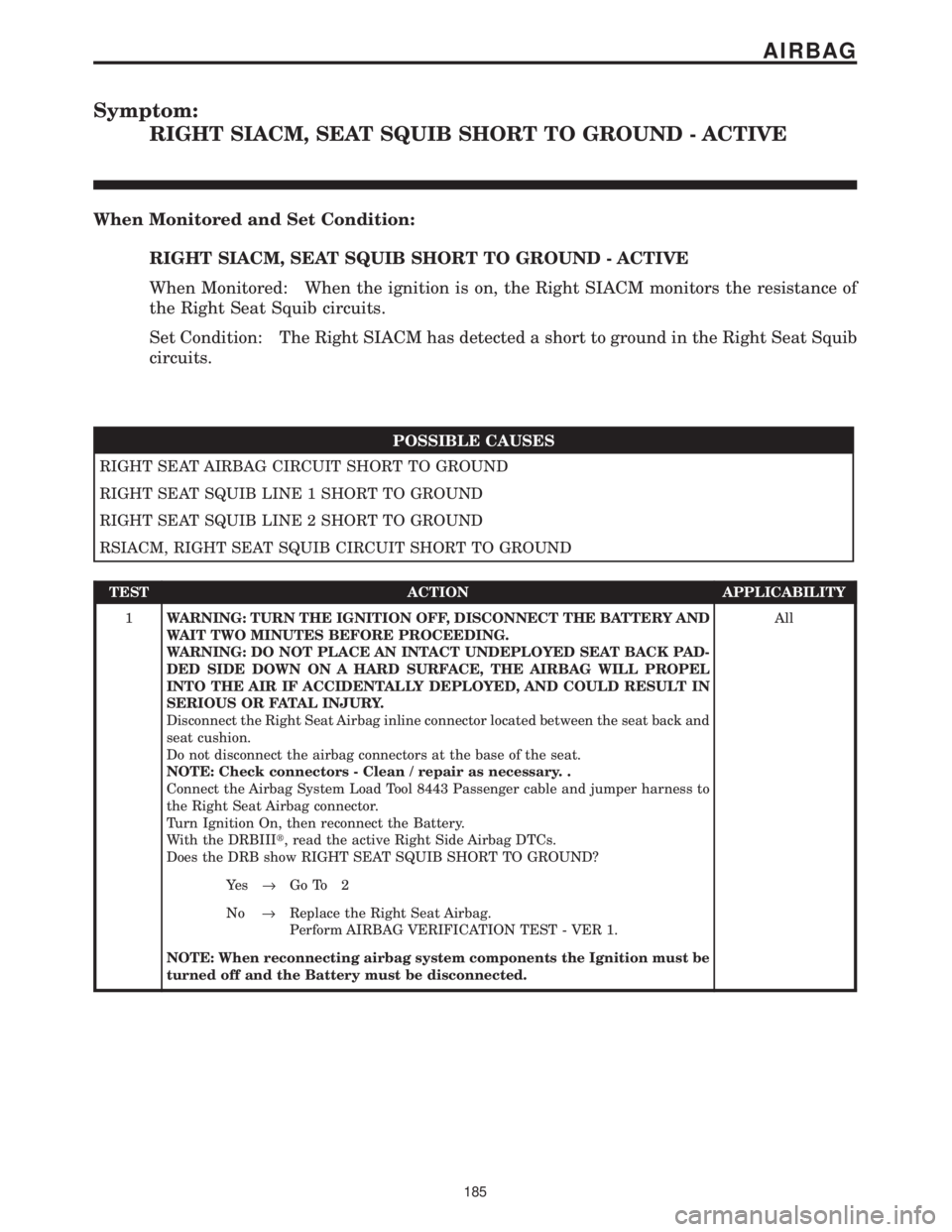
Symptom:
RIGHT SIACM, SEAT SQUIB SHORT TO GROUND - ACTIVE
When Monitored and Set Condition:
RIGHT SIACM, SEAT SQUIB SHORT TO GROUND - ACTIVE
When Monitored: When the ignition is on, the Right SIACM monitors the resistance of
the Right Seat Squib circuits.
Set Condition: The Right SIACM has detected a short to ground in the Right Seat Squib
circuits.
POSSIBLE CAUSES
RIGHT SEAT AIRBAG CIRCUIT SHORT TO GROUND
RIGHT SEAT SQUIB LINE 1 SHORT TO GROUND
RIGHT SEAT SQUIB LINE 2 SHORT TO GROUND
RSIACM, RIGHT SEAT SQUIB CIRCUIT SHORT TO GROUND
TEST ACTION APPLICABILITY
1WARNING: TURN THE IGNITION OFF, DISCONNECT THE BATTERY AND
WAIT TWO MINUTES BEFORE PROCEEDING.
WARNING: DO NOT PLACE AN INTACT UNDEPLOYED SEAT BACK PAD-
DED SIDE DOWN ON A HARD SURFACE, THE AIRBAG WILL PROPEL
INTO THE AIR IF ACCIDENTALLY DEPLOYED, AND COULD RESULT IN
SERIOUS OR FATAL INJURY.
Disconnect the Right Seat Airbag inline connector located between the seat back and
seat cushion.
Do not disconnect the airbag connectors at the base of the seat.
NOTE: Check connectors - Clean / repair as necessary. .
Connect the Airbag System Load Tool 8443 Passenger cable and jumper harness to
the Right Seat Airbag connector.
Turn Ignition On, then reconnect the Battery.
With the DRBIIIt, read the active Right Side Airbag DTCs.
Does the DRB show RIGHT SEAT SQUIB SHORT TO GROUND?All
Ye s®Go To 2
No®Replace the Right Seat Airbag.
Perform AIRBAG VERIFICATION TEST - VER 1.
NOTE: When reconnecting airbag system components the Ignition must be
turned off and the Battery must be disconnected.
185
AIRBAG
Page 219 of 4284
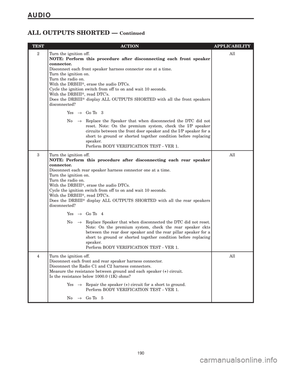
TEST ACTION APPLICABILITY
2 Turn the ignition off.
NOTE: Perform this procedure after disconnecting each front speaker
connector.
Disconnect each front speaker harness connector one at a time.
Turn the ignition on.
Turn the radio on.
With the DRBIIIt, erase the audio DTCs.
Cycle the ignition switch from off to on and wait 10 seconds.
With the DRBIIIt, read DTC's.
Does the DRBIIItdisplay ALL OUTPUTS SHORTED with all the front speakers
disconnected?All
Ye s®Go To 3
No®Replace the Speaker that when disconnected the DTC did not
reset. Note: On the premium system, check the I/P speaker
circuits between the front door speaker and the I/P speaker for a
short to ground or shorted together condition before replacing
speaker.
Perform BODY VERIFICATION TEST - VER 1.
3 Turn the ignition off.
NOTE: Perform this procedure after disconnecting each rear speaker
connector.
Disconnect each rear speaker harness connector one at a time.
Turn the ignition on.
Turn the radio on.
With the DRBIIIt, erase the audio DTCs.
Cycle the ignition switch from off to on and wait 10 seconds.
With the DRBIIIt, read DTC's.
Does the DRBIIItdisplay ALL OUTPUTS SHORTED with all the rear speakers
disconnected?All
Ye s®Go To 4
No®Replace Speaker that when disconnected the DTC did not reset.
Note: On the premium system, check the rear speaker ckts
between the rear door speaker and the rear pillar speaker for a
short to ground or shorted together condition before replacing
speaker.
Perform BODY VERIFICATION TEST - VER 1.
4 Turn the ignition off.
Disconnect each front and rear speaker harness connector.
Disconnect the Radio C1 and C2 harness connectors.
Measure the resistance between ground and each speaker (+) circuit.
Is the resistance below 1000.0 (1K) ohms?All
Ye s®Repair the speaker (+) circuit for a short to ground.
Perform BODY VERIFICATION TEST - VER 1.
No®Go To 5
190
AUDIO
ALL OUTPUTS SHORTED ÐContinued
Page 224 of 4284
Symptom:
CD CHANGER MECHANICAL FAILURE
When Monitored and Set Condition:
CD CHANGER MECHANICAL FAILURE
When Monitored: Continuously with the ignition and CD Changer turned on.
Set Condition: The code will set if the CD Changer detects a mechanical failure.
POSSIBLE CAUSES
INTERNAL FAILURE
TEST ACTION APPLICABILITY
1 This is an internal CD Changer failure.
View repairAll
Repair
Replace the CD Changer.
Perform BODY VERIFICATION TEST - VER 1.
195
AUDIO
Page 226 of 4284
Symptom:
CD CHANGER POWER SUPPLY TOO HIGH
When Monitored and Set Condition:
CD CHANGER POWER SUPPLY TOO HIGH
When Monitored: Continuously with the ignition and CD Changer turned on.
Set Condition: The code will set if the radio detects voltage above 16.0 volts for 5 seconds.
POSSIBLE CAUSES
CD CHANGER POWER SUPPLY TOO HIGH
POWER SUPPLY OF CD CHANGER
TEST ACTION APPLICABILITY
1 Turn the ignition off.
Disconnect the CD Changer harness connector.
Start the engine.
Measure the voltage of the Ignition Switch Output circuit.
Is the voltage above 16.0 volts?All
Ye s®Repair the charging system as necessary.
Perform BODY VERIFICATION TEST - VER 1.
No®Replace the CD Changer.
Perform BODY VERIFICATION TEST - VER 1.
197
AUDIO
Page 231 of 4284
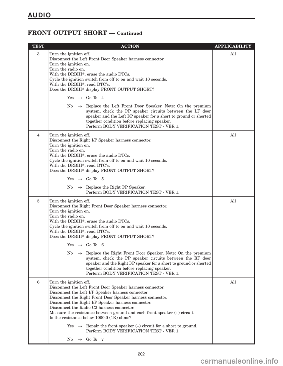
TEST ACTION APPLICABILITY
3 Turn the ignition off.
Disconnect the Left Front Door Speaker harness connector.
Turn the ignition on.
Turn the radio on.
With the DRBIIIt, erase the audio DTCs.
Cycle the ignition switch from off to on and wait 10 seconds.
With the DRBIIIt, read DTC's.
Does the DRBIIItdisplay FRONT OUTPUT SHORT?All
Ye s®Go To 4
No®Replace the Left Front Door Speaker. Note: On the premium
system, check the I/P speaker circuits between the LF door
speaker and the Left I/P speaker for a short to ground or shorted
together condition before replacing speaker.
Perform BODY VERIFICATION TEST - VER 1.
4 Turn the ignition off.
Disconnect the Right I/P Speaker harness connector.
Turn the ignition on.
Turn the radio on.
With the DRBIIIt, erase the audio DTCs.
Cycle the ignition switch from off to on and wait 10 seconds.
With the DRBIIIt, read DTC's.
Does the DRBIIItdisplay FRONT OUTPUT SHORT?All
Ye s®Go To 5
No®Replace the Right I/P Speaker.
Perform BODY VERIFICATION TEST - VER 1.
5 Turn the ignition off.
Disconnect the Right Front Door Speaker harness connector.
Turn the ignition on.
Turn the radio on.
With the DRBIIIt, erase the audio DTCs.
Cycle the ignition switch from off to on and wait 10 seconds.
With the DRBIIIt, read DTC's.
Does the DRBIIItdisplay FRONT OUTPUT SHORT?All
Ye s®Go To 6
No®Replace the Right Front Door Speaker. Note: On the premium
system, check the I/P speaker circuits between the RF door
speaker and the Right I/P speaker for a short to ground or shorted
together condition before replacing speaker.
Perform BODY VERIFICATION TEST - VER 1.
6 Turn the ignition off.
Disconnect the Left Front Door Speaker harness connector.
Disconnect the Left I/P Speaker harness connector.
Disconnect the Right Front Door Speaker harness connector.
Disconnect the Right I/P Speaker harness connector.
Disconnect the Radio C2 harness connector.
Measure the resistance between ground and each front speaker (+) circuit.
Is the resistance below 1000.0 (1K) ohms?All
Ye s®Repair the front speaker (+) circuit for a short to ground.
Perform BODY VERIFICATION TEST - VER 1.
No®Go To 7
202
AUDIO
FRONT OUTPUT SHORT ÐContinued
Page 242 of 4284
Symptom:
POWER SUPPLY TOO HIGH
When Monitored and Set Condition:
POWER SUPPLY TOO HIGH
When Monitored: Continuously with the ignition and Radio turned on.
Set Condition: The code will set if the radio detects voltage above 16.0 volts for 5 seconds.
POSSIBLE CAUSES
POWER SUPPLY TOO HIGH
POWER SUPPLY OF RADIO
TEST ACTION APPLICABILITY
1 Turn the ignition off.
Disconnect the Radio C1 harness connector.
Start the engine.
Measure the voltage of the Fused B+ circuit.
Is the voltage above 16.0 volts?All
Ye s®Repair the charging system as necessary.
Perform BODY VERIFICATION TEST - VER 1.
No®Replace the Radio.
Perform BODY VERIFICATION TEST - VER 1.
213
AUDIO