2001 CHRYSLER VOYAGER engine
[x] Cancel search: enginePage 3063 of 4284
(2) Loosen pan bolts and tap the pan at one corner
to break it loose allowing fluid to drain, then remove
the oil pan.
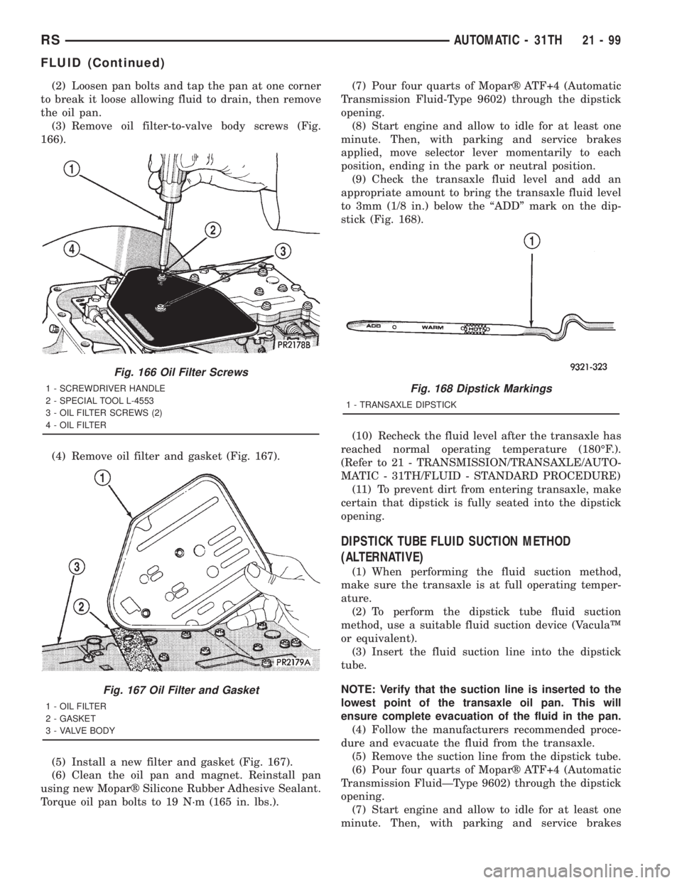
(3) Remove oil filter-to-valve body screws (Fig.
166).
(4) Remove oil filter and gasket (Fig. 167).
(5) Install a new filter and gasket (Fig. 167).
(6) Clean the oil pan and magnet. Reinstall pan
using new Moparž Silicone Rubber Adhesive Sealant.
Torque oil pan bolts to 19 N´m (165 in. lbs.).(7) Pour four quarts of Moparž ATF+4 (Automatic
Transmission Fluid-Type 9602) through the dipstick
opening.
(8) Start engine and allow to idle for at least one
minute. Then, with parking and service brakes
applied, move selector lever momentarily to each
position, ending in the park or neutral position.
(9) Check the transaxle fluid level and add an
appropriate amount to bring the transaxle fluid level
to 3mm (1/8 in.) below the ªADDº mark on the dip-
stick (Fig. 168).
(10) Recheck the fluid level after the transaxle has
reached normal operating temperature (180ÉF.).
(Refer to 21 - TRANSMISSION/TRANSAXLE/AUTO-
MATIC - 31TH/FLUID - STANDARD PROCEDURE)
(11) To prevent dirt from entering transaxle, make
certain that dipstick is fully seated into the dipstick
opening.
DIPSTICK TUBE FLUID SUCTION METHOD
(ALTERNATIVE)
(1) When performing the fluid suction method,
make sure the transaxle is at full operating temper-
ature.
(2) To perform the dipstick tube fluid suction
method, use a suitable fluid suction device (VaculaŸ
or equivalent).
(3) Insert the fluid suction line into the dipstick
tube.
NOTE: Verify that the suction line is inserted to the
lowest point of the transaxle oil pan. This will
ensure complete evacuation of the fluid in the pan.
(4) Follow the manufacturers recommended proce-
dure and evacuate the fluid from the transaxle.
(5) Remove the suction line from the dipstick tube.
(6) Pour four quarts of Moparž ATF+4 (Automatic
Transmission FluidÐType 9602) through the dipstick
opening.
(7) Start engine and allow to idle for at least one
minute. Then, with parking and service brakes
Fig. 166 Oil Filter Screws
1 - SCREWDRIVER HANDLE
2 - SPECIAL TOOL L-4553
3 - OIL FILTER SCREWS (2)
4 - OIL FILTER
Fig. 167 Oil Filter and Gasket
1 - OIL FILTER
2 - GASKET
3 - VALVE BODY
Fig. 168 Dipstick Markings
1 - TRANSAXLE DIPSTICK
RSAUTOMATIC - 31TH21-99
FLUID (Continued)
Page 3065 of 4284
INSTALLATION
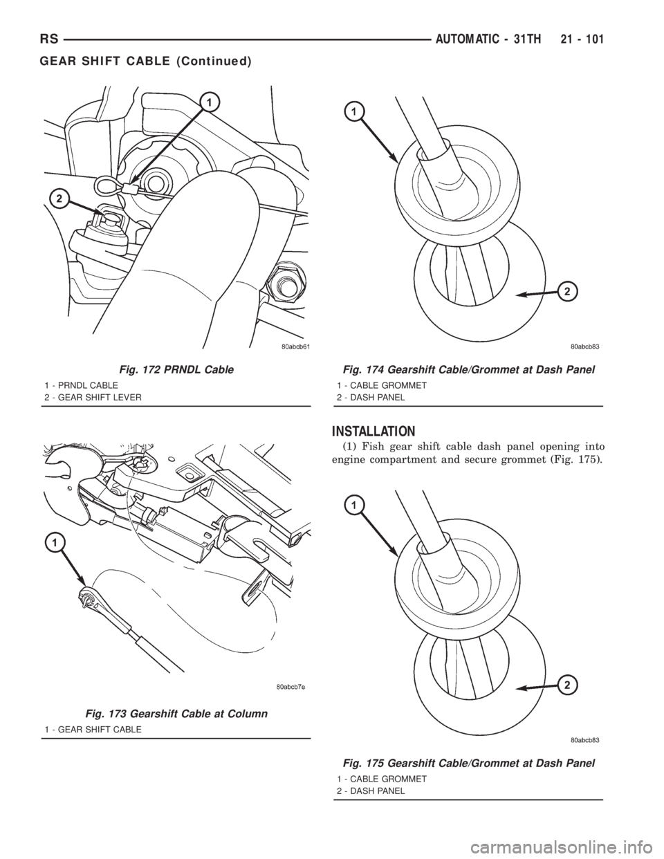
(1) Fish gear shift cable dash panel opening into
engine compartment and secure grommet (Fig. 175).
Fig. 172 PRNDL Cable
1 - PRNDL CABLE
2 - GEAR SHIFT LEVER
Fig. 173 Gearshift Cable at Column
1 - GEAR SHIFT CABLE
Fig. 174 Gearshift Cable/Grommet at Dash Panel
1 - CABLE GROMMET
2 - DASH PANEL
Fig. 175 Gearshift Cable/Grommet at Dash Panel
1 - CABLE GROMMET
2 - DASH PANEL
RSAUTOMATIC - 31TH21 - 101
GEAR SHIFT CABLE (Continued)
Page 3068 of 4284
pressure. Generally governor pressure ranges from
0-100 psi from idle to maximum speed, and rises pro-
portionally with the increase in output shaft speed.
Governor pressure and throttle pressure are acting
upon the shift valves to determine when a shift will
occur. Governor pressure is a direct indication of road
speed, and throttle pressure is an indication of
engine load. When both parameters have been met
by the throttle and governor pressures, an upshift or
downshift will occur.
CLEANING
Thoroughly clean all the governor parts in a suit-
able cleaning solution but do not use any type of
caustic cleaning agents.
The governor weight components and the governor
valve, must slide freely in their bores when clean and
dry. Minor surface scratches and burrs can be
smoothed with crocus cloth.
INSPECTION
The aluminum governor valve and outer weight
have a hard coating on them. Check condition of this
coating carefully. Do not reuse either part if the coat-
ing is damaged.
Inspect the governor weight spring for distortion.
Replace the spring, if distorted, collapsed, or broken.
Clean the filter in solvent and dry it with compressedair. Replace the filter, if damaged. Inspect the park
gear for chipped or worn gear teeth or damaged ring
grooves. Replace the gear, if damaged.
Check the teeth on the park gear for wear or dam-
age. Replace the gear if necessary. Inspect the metal
seal rings on the park gear hub. Replace the rings
only if severely worn, or broken.
OIL PUMP
DESCRIPTION
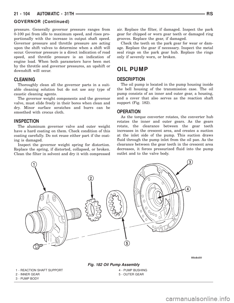
The oil pump is located in the pump housing inside
the bell housing of the transmission case. The oil
pump consists of an inner and outer gear, a housing,
and a cover that also serves as the reaction shaft
support (Fig. 182).
OPERATION
As the torque converter rotates, the converter hub
rotates the inner and outer gears. As the gears
rotate, the clearance between the gear teeth
increases in the crescent area, and creates a suction
at the inlet side of the pump. This suction draws
fluid through the pump inlet from the oil pan. As the
clearance between the gear teeth in the crescent area
decreases, it forces pressurized fluid into the pump
outlet and to the valve body.
Fig. 182 Oil Pump Assembly
1 - REACTION SHAFT SUPPORT
2 - INNER GEAR
3 - PUMP BODY4 - PUMP BUSHING
5 - OUTER GEAR
21 - 104 AUTOMATIC - 31THRS
GOVERNOR (Continued)
Page 3069 of 4284
STANDARD PROCEDURE - OIL PUMP VOLUME
CHECK
Measuring the oil pump output volume will deter-
mine if sufficient oil flow to the transmission oil
cooler exists, and whether or not an internal trans-
mission failure is present.
Verify that the transmission fluid is at the proper
level. Refer to the Fluid Level Check procedure in
this section. If necessary, fill the transmission to the
proper level with Moparž ATF +4, type 9602, Auto-
matic Transmission Fluid.
(1) Using hose cutters or a suitable blade, cut the
To coolerline off flush with the cooler inlet fitting
and place a collecting container under the open line.
CAUTION: With the fluid set at the proper level,
fluid collection should not exceed (1) quart or inter-
nal damage to the transmission may occur.
(2) Run the engineat curb idle speed, with the
shift selector in neutral.
(3) If one quart of transmission fluid is collected in
the container in 20 seconds or less, oil pump flow vol-
ume is within acceptable limits. If fluid flow is inter-
mittent, or it takes more than 20 seconds to collect
one quart of fluid, (Refer to 21 - TRANSMISSION/
TRANSAXLE/AUTOMATIC - 31TH - DIAGNOSIS
AND TESTING) for further diagnosis.
(4) Re-connect theTo coolerline to the transmis-
sion cooler inlet using a service splice kit. Refer to
instructions included with the kit.
(5) Refill the transmission to proper level. (Refer
to 21 - TRANSMISSION/TRANSAXLE/AUTOMATIC
- 31TH/FLUID - STANDARD PROCEDURE)
DISASSEMBLY
(1) Remove reaction shaft support-to-pump body
bolts.
(2) Remove reaction shaft support, and the inner
and outer pump gears (Fig. 183).
CLEANING
Clean pump and support components with solvent
and dry them with compressed air.
INSPECTION
(1) Check condition of the seal rings and thrust
washer on the reaction shaft support. The seal rings
do not need to be replaced unless cracked, broken, or
severely worn.
(2) Visually inspect the pump and support compo-
nents. Replace the pump assembly if the seal ring
grooves or machined surfaces are worn, scored, pit-
ted, or damaged. Replace the pump assembly if the
gears if pitted, worn chipped, or damaged.
(3) Inspect the pump bushing. Then check the
reaction shaft support bushing. Replace the pump
assembly if either bushing is heavily worn, scored or
damaged.
(4) Clearance between outer gear and reaction
shaft housing should be 0.010 to 0.063 mm (0.0004 to
0.0025 in.). Clearance between inner gear and reac-
tion shaft housing should be 0.010 to 0.063 mm
(0.0004 to 0.0025 in.). Both clearances can be mea-
sured at the same time by installing the gears in the
pump body and measure pump component clearances
as follows:
(5) Reinstall gears to pump body and measure
outer gear-to-pocket clearance with a feeler gauge
(Fig. 184).Outer gear-to-pocket clearance should
be within 0.045-0.141 mm (0.0018-0.0056 in.).
(6) Measure both inner and outer gear side clear-
ance with PlastigageŸ. If PlastigageŸ is not avail-
able, measure across the pump body with a straight
edge and feeler gauge.
(a) Position an appropriate piece of PlastigageŸ
across both gears.
(b) Align the plastigage to a flat area on the
reaction shaft housing.
(c) Install the reaction shaft support to the
pump housing and torque to 28 N´m (250 in. lbs.).
(d) Separate the reaction shaft housing from the
pump housing and measure the PlastigageŸ fol-
lowing the instructions supplied with it.Inner
and outer gear side clearance should be
within 0.020-0.046 mm (0.0008-0.0018 in.).
ASSEMBLY
(1) Install inner and outer gears to pump body
(Fig. 183). Lubricate gears with Moparž ATF+4
(Automatic Transmission Fluid-Type 9602).
(2) Install reaction shaft support to pump body
and align holes.
(3) Install and torque reaction shaft support-to-
pump body bolts to 28 N´m (250 in. lbs.).
RSAUTOMATIC - 31TH21 - 105
OIL PUMP (Continued)
Page 3073 of 4284
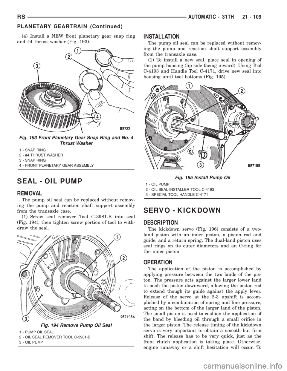
(4) Install a NEW front planetary gear snap ring
and #4 thrust washer (Fig. 193).
SEAL - OIL PUMP
REMOVAL
The pump oil seal can be replaced without remov-
ing the pump and reaction shaft support assembly
from the transaxle case.
(1) Screw seal remover Tool C-3981-B into seal
(Fig. 194), then tighten screw portion of tool to with-
draw the seal.
INSTALLATION
The pump oil seal can be replaced without remov-
ing the pump and reaction shaft support assembly
from the transaxle case.
(1) To install a new seal, place seal in opening of
the pump housing (lip side facing inward). Using Tool
C-4193 and Handle Tool C-4171, drive new seal into
housing until tool bottoms (Fig. 195).
SERVO - KICKDOWN
DESCRIPTION
The kickdown servo (Fig. 196) consists of a two-
land piston with an inner piston, a piston rod and
guide, and a return spring. The dual-land piston uses
seal rings on its outer diameters and an O-ring for
the inner piston.
OPERATION
The application of the piston is accomplished by
applying pressure between the two lands of the pis-
ton. The pressure acts against the larger lower land
to push the piston downward, allowing the piston rod
to extend though its guide against the apply lever.
Release of the servo at the 2-3 upshift is accom-
plished by a combination of spring and line pressure,
acting on the bottom of the larger land of the piston.
The small piston is used to cushion the application of
the band by bleeding oil through a small orifice in
the larger piston. The release timing of the kickdown
servo is very important to obtain a smooth but firm
shift. The release has to be very quick, just as the
front clutch application is taking place. Otherwise,
engine runaway or a shift hesitation will occur. To
Fig. 193 Front Planetary Gear Snap Ring and No. 4
Thrust Washer
1 - SNAP RING
2 - #4 THRUST WASHER
3 - SNAP RING
4 - FRONT PLANETARY GEAR ASSEMBLY
Fig. 194 Remove Pump Oil Seal
1 - PUMP OIL SEAL
2 - OIL SEAL REMOVER TOOL C-3981-B
3 - OIL PUMP
Fig. 195 Install Pump Oil
1 - OIL PUMP
2 - OIL SEAL INSTALLER TOOL C-4193
3 - SPECIAL TOOL HANDLE C-4171
RSAUTOMATIC - 31TH21 - 109
PLANETARY GEARTRAIN (Continued)
Page 3084 of 4284
THROTTLE VALVE LINKAGE ADJUSTMENT
The throttle valve linkage adjustment is very
important to proper transaxle operation. This adjust-
ment positions a valve which controls shift speed,
shift quality, and part throttle downshift sensitivity.
If the setting is too short, early shifts and slippage
between shifts may occur. If the setting is too long,
shifts may be delayed and part throttle downshifts
may be very sensitive.
LINKAGE ADJUSTMENT PROCEDURE
(1) Perform transaxle throttle valve linkage
adjustment while engine is at normal operating tem-
perature.
(2) Using small screwdriver, disengage adjustment
lock at transaxle.
(3) Rotate lever at transaxle all the way to the left
side of vehicle against stop.
(4) Slide cable adjuster until cable core end
touches clip at throttle valve lever.
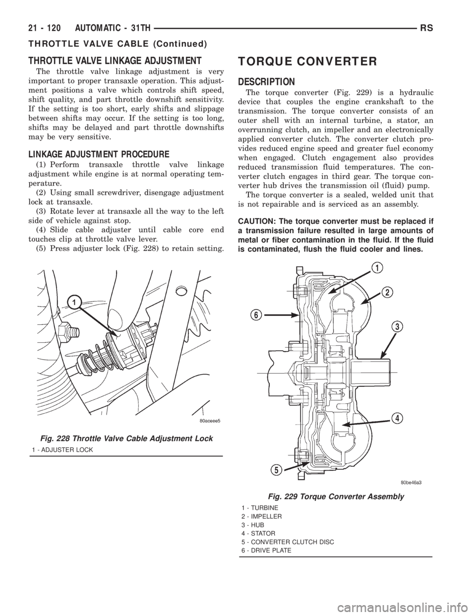
(5) Press adjuster lock (Fig. 228) to retain setting.
TORQUE CONVERTER
DESCRIPTION
The torque converter (Fig. 229) is a hydraulic
device that couples the engine crankshaft to the
transmission. The torque converter consists of an
outer shell with an internal turbine, a stator, an
overrunning clutch, an impeller and an electronically
applied converter clutch. The converter clutch pro-
vides reduced engine speed and greater fuel economy
when engaged. Clutch engagement also provides
reduced transmission fluid temperatures. The con-
verter clutch engages in third gear. The torque con-
verter hub drives the transmission oil (fluid) pump.
The torque converter is a sealed, welded unit that
is not repairable and is serviced as an assembly.
CAUTION: The torque converter must be replaced if
a transmission failure resulted in large amounts of
metal or fiber contamination in the fluid. If the fluid
is contaminated, flush the fluid cooler and lines.
Fig. 228 Throttle Valve Cable Adjustment Lock
1 - ADJUSTER LOCK
Fig. 229 Torque Converter Assembly
1 - TURBINE
2 - IMPELLER
3 - HUB
4-STATOR
5 - CONVERTER CLUTCH DISC
6 - DRIVE PLATE
21 - 120 AUTOMATIC - 31THRS
THROTTLE VALVE CABLE (Continued)
Page 3085 of 4284
IMPELLER
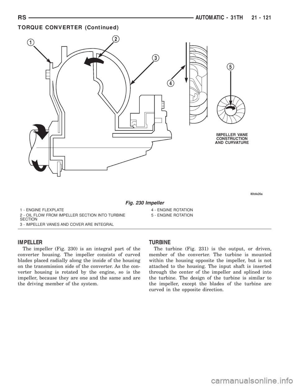
The impeller (Fig. 230) is an integral part of the
converter housing. The impeller consists of curved
blades placed radially along the inside of the housing
on the transmission side of the converter. As the con-
verter housing is rotated by the engine, so is the
impeller, because they are one and the same and are
the driving member of the system.
TURBINE
The turbine (Fig. 231) is the output, or driven,
member of the converter. The turbine is mounted
within the housing opposite the impeller, but is not
attached to the housing. The input shaft is inserted
through the center of the impeller and splined into
the turbine. The design of the turbine is similar to
the impeller, except the blades of the turbine are
curved in the opposite direction.
Fig. 230 Impeller
1 - ENGINE FLEXPLATE
2 - OIL FLOW FROM IMPELLER SECTION INTO TURBINE
SECTION
3 - IMPELLER VANES AND COVER ARE INTEGRAL4 - ENGINE ROTATION
5 - ENGINE ROTATION
RSAUTOMATIC - 31TH21 - 121
TORQUE CONVERTER (Continued)
Page 3086 of 4284
STATOR
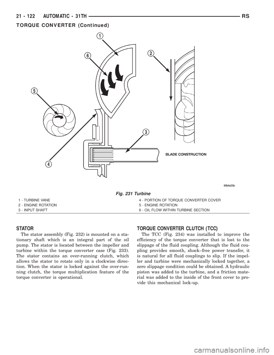
The stator assembly (Fig. 232) is mounted on a sta-
tionary shaft which is an integral part of the oil
pump. The stator is located between the impeller and
turbine within the torque converter case (Fig. 233).
The stator contains an over-running clutch, which
allows the stator to rotate only in a clockwise direc-
tion. When the stator is locked against the over-run-
ning clutch, the torque multiplication feature of the
torque converter is operational.
TORQUE CONVERTER CLUTCH (TCC)
The TCC (Fig. 234) was installed to improve the
efficiency of the torque converter that is lost to the
slippage of the fluid coupling. Although the fluid cou-
pling provides smooth, shock±free power transfer, it
is natural for all fluid couplings to slip. If the impel-
ler and turbine were mechanically locked together, a
zero slippage condition could be obtained. A hydraulic
piston was added to the turbine, and a friction mate-
rial was added to the inside of the front cover to pro-
vide this mechanical lock-up.
Fig. 231 Turbine
1 - TURBINE VANE
2 - ENGINE ROTATION
3 - INPUT SHAFT4 - PORTION OF TORQUE CONVERTER COVER
5 - ENGINE ROTATION
6 - OIL FLOW WITHIN TURBINE SECTION
21 - 122 AUTOMATIC - 31THRS
TORQUE CONVERTER (Continued)