2001 CHRYSLER VOYAGER check engine light
[x] Cancel search: check engine lightPage 4072 of 4284
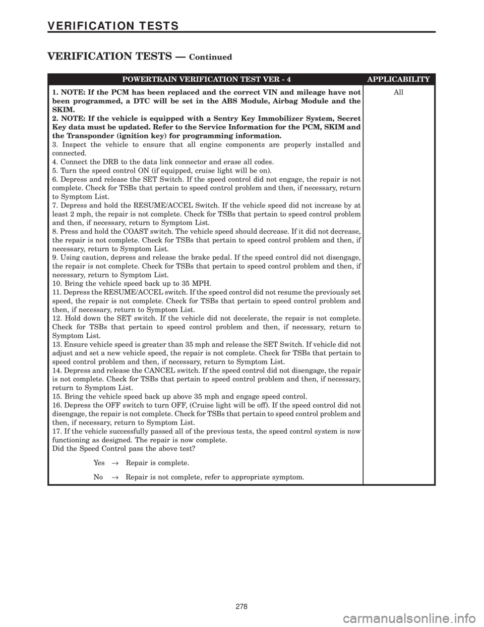
POWERTRAIN VERIFICATION TEST VER - 4 APPLICABILITY
1. NOTE: If the PCM has been replaced and the correct VIN and mileage have not
been programmed, a DTC will be set in the ABS Module, Airbag Module and the
SKIM.
2. NOTE: If the vehicle is equipped with a Sentry Key Immobilizer System, Secret
Key data must be updated. Refer to the Service Information for the PCM, SKIM and
the Transponder (ignition key) for programming information.
3. Inspect the vehicle to ensure that all engine components are properly installed and
connected.
4. Connect the DRB to the data link connector and erase all codes.
5. Turn the speed control ON (if equipped, cruise light will be on).
6. Depress and release the SET Switch. If the speed control did not engage, the repair is not
complete. Check for TSBs that pertain to speed control problem and then, if necessary, return
to Symptom List.
7. Depress and hold the RESUME/ACCEL Switch. If the vehicle speed did not increase by at
least 2 mph, the repair is not complete. Check for TSBs that pertain to speed control problem
and then, if necessary, return to Symptom List.
8. Press and hold the COAST switch. The vehicle speed should decrease. If it did not decrease,
the repair is not complete. Check for TSBs that pertain to speed control problem and then, if
necessary, return to Symptom List.
9. Using caution, depress and release the brake pedal. If the speed control did not disengage,
the repair is not complete. Check for TSBs that pertain to speed control problem and then, if
necessary, return to Symptom List.
10. Bring the vehicle speed back up to 35 MPH.
11. Depress the RESUME/ACCEL switch. If the speed control did not resume the previously set
speed, the repair is not complete. Check for TSBs that pertain to speed control problem and
then, if necessary, return to Symptom List.
12. Hold down the SET switch. If the vehicle did not decelerate, the repair is not complete.
Check for TSBs that pertain to speed control problem and then, if necessary, return to
Symptom List.
13. Ensure vehicle speed is greater than 35 mph and release the SET Switch. If vehicle did not
adjust and set a new vehicle speed, the repair is not complete. Check for TSBs that pertain to
speed control problem and then, if necessary, return to Symptom List.
14. Depress and release the CANCEL switch. If the speed control did not disengage, the repair
is not complete. Check for TSBs that pertain to speed control problem and then, if necessary,
return to Symptom List.
15. Bring the vehicle speed back up above 35 mph and engage speed control.
16. Depress the OFF switch to turn OFF, (Cruise light will be off). If the speed control did not
disengage, the repair is not complete. Check for TSBs that pertain to speed control problem and
then, if necessary, return to Symptom List.
17. If the vehicle successfully passed all of the previous tests, the speed control system is now
functioning as designed. The repair is now complete.
Did the Speed Control pass the above test?All
Ye s®Repair is complete.
No®Repair is not complete, refer to appropriate symptom.
278
VERIFICATION TESTS
VERIFICATION TESTS ÐContinued
Page 4113 of 4284
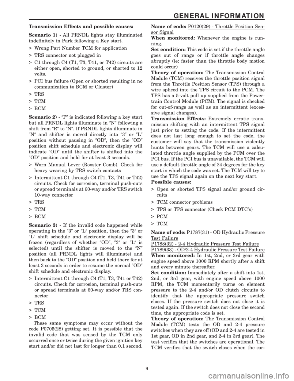
Transmission Effects and possible causes:
Scenario 1)- All PRNDL lights stay illuminated
indefinitely in Park following a Key start.
> Wrong Part Number TCM for application
> TRS connector not plugged in
> C1 through C4 (T1, T3, T41, or T42) circuits are
either open, shorted to ground, or shorted to 12
volts.
> PCI bus failure (Open or shorted resulting in no
communication to BCM or Cluster)
> TRS
> TCM
> BCM
Scenario 2)-9P9is indicated following a key start
but all PRNDL lights illuminate in9N9following a
shift from9R9to9N9. If PRNDL lights illuminate in
9N9and shifter is moved directly into939or9L9
position without pausing in9OD9, then the9OD9
position shift schedule and electronic display will
indicate9OD9until the shifter is shifted into the
9OD9position and held for at least 3 seconds.
> Worn Manual Lever (Rooster Comb). Check for
heavy wearing by TRS switch contacts
> Intermittent C1 through C4 (T1, T3, T41 or T42)
circuits. Check for corrosion, terminal push-outs
or spread terminals at 60-way and/or TRS switch
10-way connector
> TRS
> TCM
> BCM
Scenario 3)- If the invalid code happened while
operating in the939or9L9position, then the939or
9L9shift schedule and electronic display will be
frozen (regardless of whether9OD9,939or9L9is
selected) until the shifter is moved to the9N9
position (all PRNDL lights will illuminate) and
then back to the9OD9position and held there for at
least 3 seconds in order to resume the normal9OD9
shift schedule and electronic display.
> Intermittent C1 through C4 (T1, T3, T41 or T42)
circuits. Check for corrosion, terminal push-outs
or spread terminals at 60-way and/or TRS con-
nector
> TRS
> TCM
> BCM
These same symptoms may occur without the
code P0705(28) getting set. It is possible that the
invalid code that was sensed by the TCM only
occurred once or twice during the given ignition key
start and/or did not last for longer than 0.1 second.Name of code:P0120(29) - Throttle Position Sen-
sor Signal
When monitored:Whenever the engine is run-
ning.
Set condition:This code is set if the throttle angle
goes out of range or if throttle angle changes
abruptly (ie: faster than the throttle body motion
could occur)
Theory of operation:The Transmission Control
Module (TCM) receives the throttle position signal
from the Throttle Position Sensor (TPS) through a
wire spliced into the TPS circuit to the PCM. The
TPS has a 5-volt pull up supplied from the Power-
train Control Module (PCM). The signal is checked
for out-of-range as well as an intermittent (exces-
sive signal changes).
Transmission Effects:Extremely erratic trans-
mission shifting with an intermittent TPS signal
just prior to setting the code. If the intermittent
does not last long enough to set the code, the
customer will say that the transmission violently
hunts between gears. The TCM will use a calcu-
lated throttle angle supplied by the PCM over the
PCI bus. If the PCI bus is unavailable, the TCM will
use a default throttle angle of 24 degrees for the key
start in which the code was set. The TCM will try to
use the TPS signal again on the next key start.
Possible causes:
> Open or shorted TPS signal and/or ground cir-
cuits
> TCM connector problems
> TPS or TPS connector (Check PCM DTC's)
> PCM
> TCM
Name of code:P1787(31) - OD Hydraulic Pressure
Test Failure
P1788(32) - 2-4 Hydraulic Pressure Test Failure
P1789(33) - OD/2-4 Hydraulic Pressure Test Failure
When monitored:In 1st, 2nd, or 3rd gear with
engine speed above 1000 RPM shortly after a shift
and every minute thereafter.
Set condition:Immediately after a shift into 1st,
2nd, or 3rd gear, with engine speed above 1000
RPM, the TCM momentarily turns on element
pressure to the 2-4 and/or OD clutch circuits to
identify that the appropriate pressure switch
closes. If the pressure switch does not close it is
tested again. If the switch does not close the second
time, the appropriate code is set.
Theory of operation:The Transmission Control
Module (TCM) tests the OD and 2-4 pressure
switches when they are off (OD and 2-4 are tested in
1st gear, OD in 2nd gear, and 2-4 in 3rd gear). The
test verifies that the switches are operational. The
TCM verifies that the switch closes when the cor-
9
GENERAL INFORMATION
Page 4168 of 4284
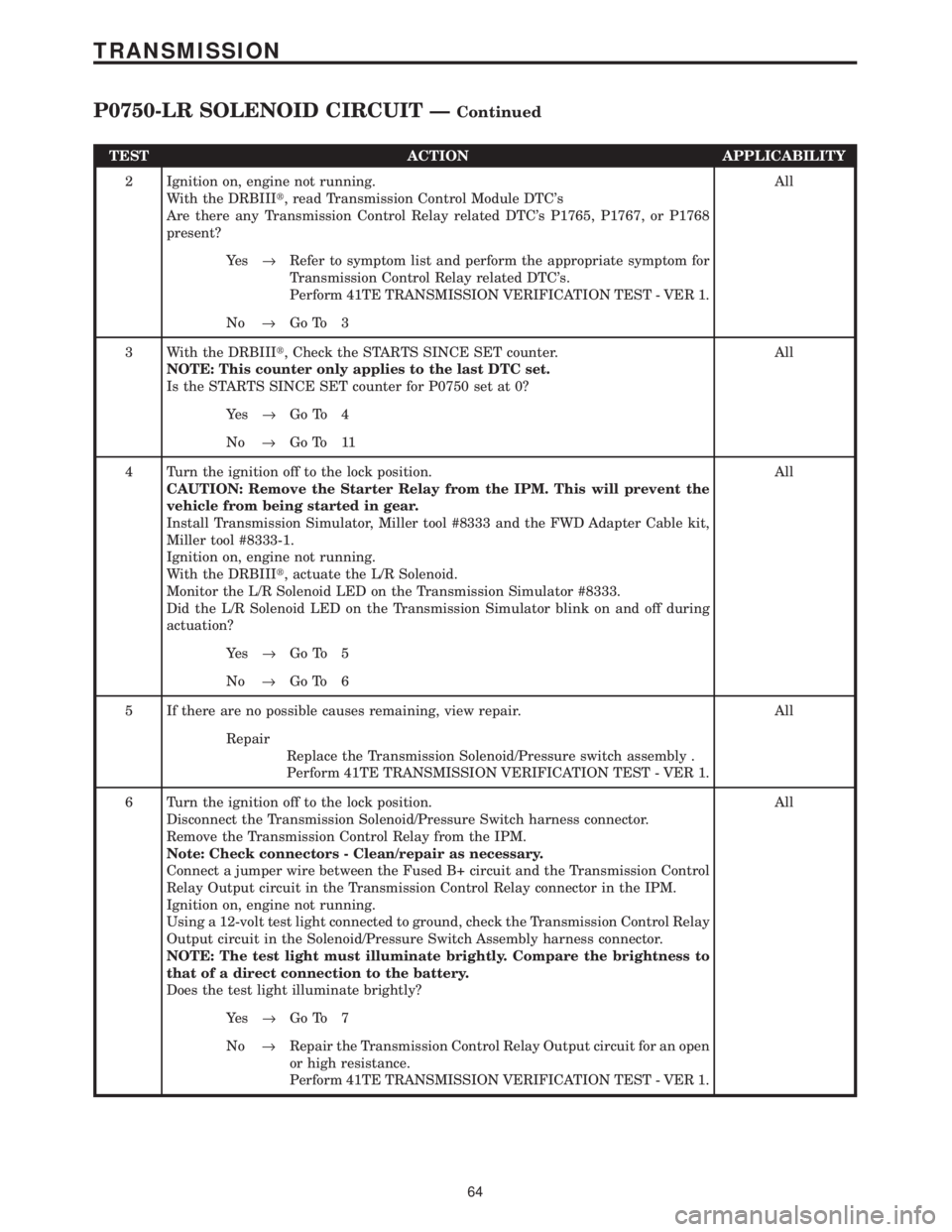
TEST ACTION APPLICABILITY
2 Ignition on, engine not running.
With the DRBIIIt, read Transmission Control Module DTC's
Are there any Transmission Control Relay related DTC's P1765, P1767, or P1768
present?All
Ye s®Refer to symptom list and perform the appropriate symptom for
Transmission Control Relay related DTC's.
Perform 41TE TRANSMISSION VERIFICATION TEST - VER 1.
No®Go To 3
3 With the DRBIIIt, Check the STARTS SINCE SET counter.
NOTE: This counter only applies to the last DTC set.
Is the STARTS SINCE SET counter for P0750 set at 0?All
Ye s®Go To 4
No®Go To 11
4 Turn the ignition off to the lock position.
CAUTION: Remove the Starter Relay from the IPM. This will prevent the
vehicle from being started in gear.
Install Transmission Simulator, Miller tool #8333 and the FWD Adapter Cable kit,
Miller tool #8333-1.
Ignition on, engine not running.
With the DRBIIIt, actuate the L/R Solenoid.
Monitor the L/R Solenoid LED on the Transmission Simulator #8333.
Did the L/R Solenoid LED on the Transmission Simulator blink on and off during
actuation?All
Ye s®Go To 5
No®Go To 6
5 If there are no possible causes remaining, view repair. All
Repair
Replace the Transmission Solenoid/Pressure switch assembly .
Perform 41TE TRANSMISSION VERIFICATION TEST - VER 1.
6 Turn the ignition off to the lock position.
Disconnect the Transmission Solenoid/Pressure Switch harness connector.
Remove the Transmission Control Relay from the IPM.
Note: Check connectors - Clean/repair as necessary.
Connect a jumper wire between the Fused B+ circuit and the Transmission Control
Relay Output circuit in the Transmission Control Relay connector in the IPM.
Ignition on, engine not running.
Using a 12-volt test light connected to ground, check the Transmission Control Relay
Output circuit in the Solenoid/Pressure Switch Assembly harness connector.
NOTE: The test light must illuminate brightly. Compare the brightness to
that of a direct connection to the battery.
Does the test light illuminate brightly?All
Ye s®Go To 7
No®Repair the Transmission Control Relay Output circuit for an open
or high resistance.
Perform 41TE TRANSMISSION VERIFICATION TEST - VER 1.
64
TRANSMISSION
P0750-LR SOLENOID CIRCUIT ÐContinued
Page 4171 of 4284
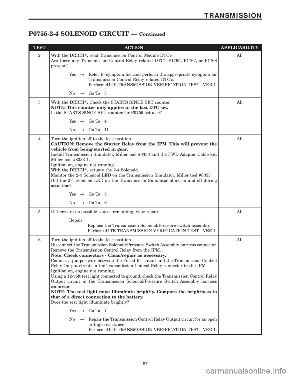
TEST ACTION APPLICABILITY
2 With the DRBIIIt, read Transmission Control Module DTC's
Are there any Transmission Control Relay related DTC's P1765, P1767, or P1768
present?.All
Ye s®Refer to symptom list and perform the appropriate symptom for
Transmission Control Relay related DTC's.
Perform 41TE TRANSMISSION VERIFICATION TEST - VER 1.
No®Go To 3
3 With the DRBIIIt, Check the STARTS SINCE SET counter.
NOTE: This counter only applies to the last DTC set.
Is the STARTS SINCE SET counter for P0755 set at 0?All
Ye s®Go To 4
No®Go To 11
4 Turn the ignition off to the lock position.
CAUTION: Remove the Starter Relay from the IPM. This will prevent the
vehicle from being started in gear.
Install Transmission Simulator, Miller tool #8333 and the FWD Adapter Cable kit,
Miller tool #8333-1.
Ignition on, engine not running.
With the DRBIIIt, actuate the 2-4 Solenoid.
Monitor the 2-4 Solenoid LED on the Transmission Simulator, Miller tool #8333
Did the 2-4 Solenoid LED on the Transmission Simulator blink on and off during
actuation?All
Ye s®Go To 5
No®Go To 6
5 If there are no possible causes remaining, view repair. All
Repair
Replace the Transmission Solenoid/Pressure switch assembly.
Perform 41TE TRANSMISSION VERIFICATION TEST - VER 1.
6 Turn the ignition off to the lock position.
Disconnect the Transmission Solenoid/Pressure Switch Assembly harness connector.
Remove the Transmission Control Relay from the IPM.
Note: Check connectors - Clean/repair as necessary.
Connect a jumper wire between the Fused B+ circuit and the Transmission Control
Relay Output circuit in the Transmission Control Relay connector in the IPM.
Ignition on, engine not running.
Using a 12-volt test light connected to ground, check the Transmission Control Relay
Output circuit in the Transmission Solenoid/Pressure Switch Assembly harness
connector.
NOTE: The test light must illuminate brightly. Compare the brightness to
that of a direct connection to the battery.
Does the test light illuminate brightly?All
Ye s®Go To 7
No®Repair the Transmission Control Relay Output circuit for an open
or high resistance.
Perform 41TE TRANSMISSION VERIFICATION TEST - VER 1.
67
TRANSMISSION
P0755-2-4 SOLENOID CIRCUIT ÐContinued
Page 4174 of 4284
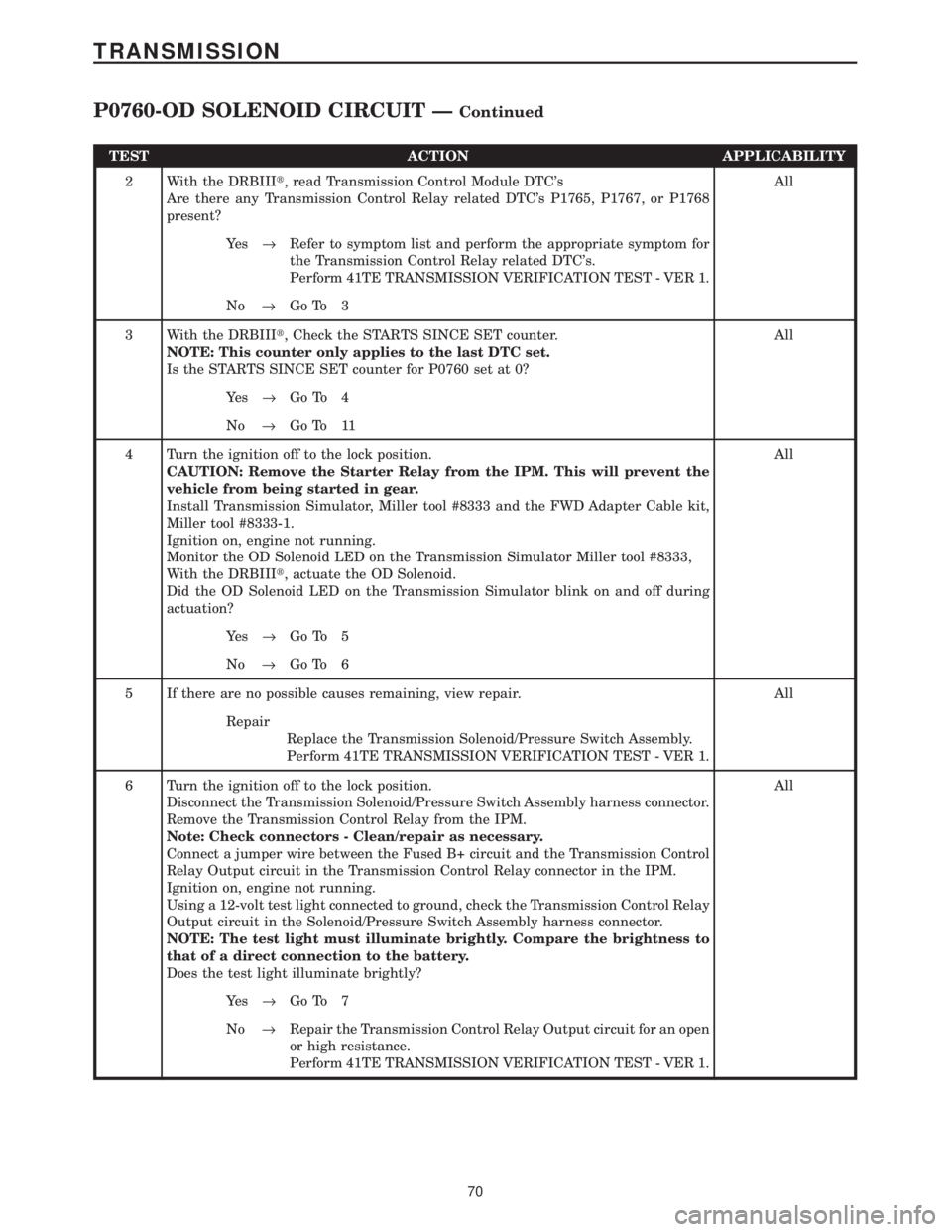
TEST ACTION APPLICABILITY
2 With the DRBIIIt, read Transmission Control Module DTC's
Are there any Transmission Control Relay related DTC's P1765, P1767, or P1768
present?All
Ye s®Refer to symptom list and perform the appropriate symptom for
the Transmission Control Relay related DTC's.
Perform 41TE TRANSMISSION VERIFICATION TEST - VER 1.
No®Go To 3
3 With the DRBIIIt, Check the STARTS SINCE SET counter.
NOTE: This counter only applies to the last DTC set.
Is the STARTS SINCE SET counter for P0760 set at 0?All
Ye s®Go To 4
No®Go To 11
4 Turn the ignition off to the lock position.
CAUTION: Remove the Starter Relay from the IPM. This will prevent the
vehicle from being started in gear.
Install Transmission Simulator, Miller tool #8333 and the FWD Adapter Cable kit,
Miller tool #8333-1.
Ignition on, engine not running.
Monitor the OD Solenoid LED on the Transmission Simulator Miller tool #8333,
With the DRBIIIt, actuate the OD Solenoid.
Did the OD Solenoid LED on the Transmission Simulator blink on and off during
actuation?All
Ye s®Go To 5
No®Go To 6
5 If there are no possible causes remaining, view repair. All
Repair
Replace the Transmission Solenoid/Pressure Switch Assembly.
Perform 41TE TRANSMISSION VERIFICATION TEST - VER 1.
6 Turn the ignition off to the lock position.
Disconnect the Transmission Solenoid/Pressure Switch Assembly harness connector.
Remove the Transmission Control Relay from the IPM.
Note: Check connectors - Clean/repair as necessary.
Connect a jumper wire between the Fused B+ circuit and the Transmission Control
Relay Output circuit in the Transmission Control Relay connector in the IPM.
Ignition on, engine not running.
Using a 12-volt test light connected to ground, check the Transmission Control Relay
Output circuit in the Solenoid/Pressure Switch Assembly harness connector.
NOTE: The test light must illuminate brightly. Compare the brightness to
that of a direct connection to the battery.
Does the test light illuminate brightly?All
Ye s®Go To 7
No®Repair the Transmission Control Relay Output circuit for an open
or high resistance.
Perform 41TE TRANSMISSION VERIFICATION TEST - VER 1.
70
TRANSMISSION
P0760-OD SOLENOID CIRCUIT ÐContinued
Page 4177 of 4284
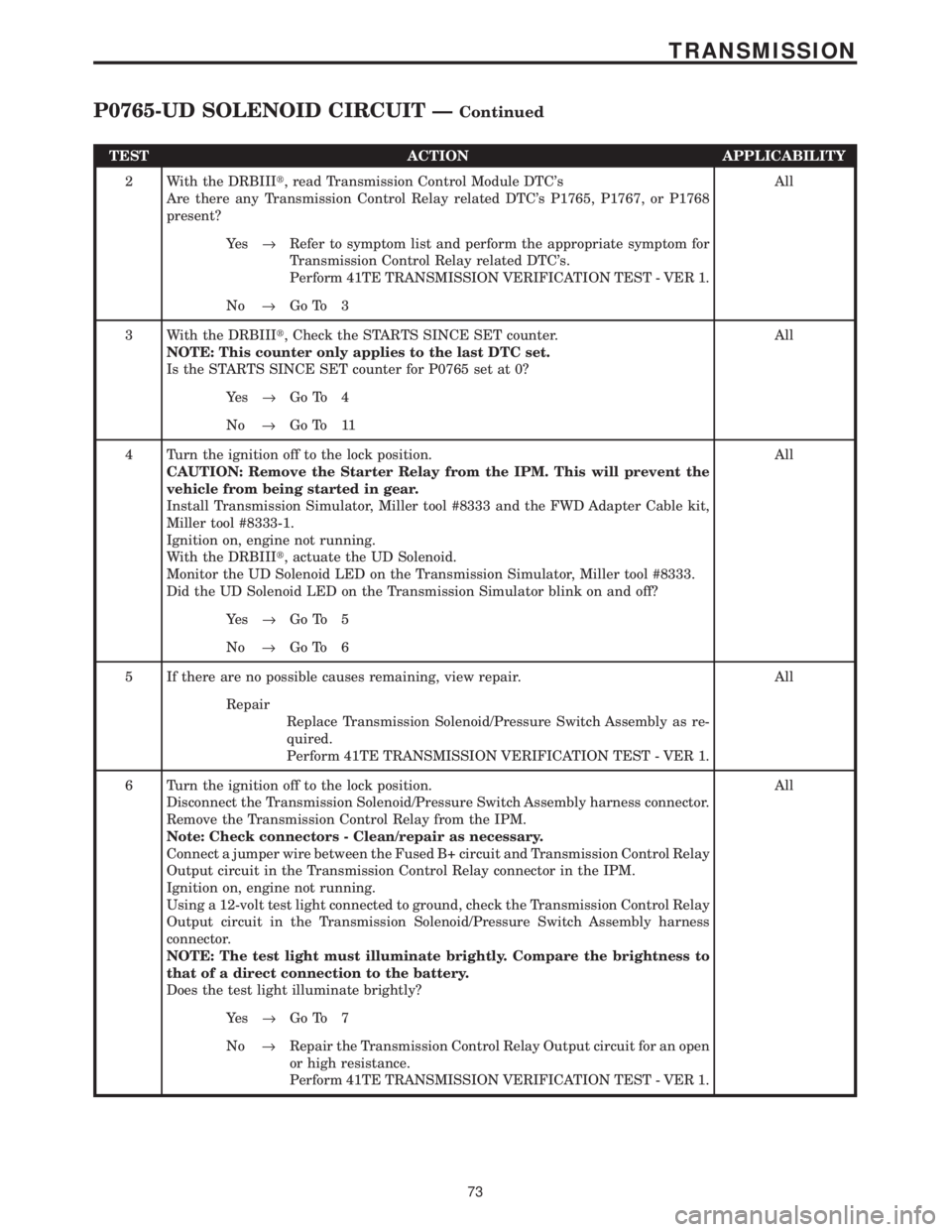
TEST ACTION APPLICABILITY
2 With the DRBIIIt, read Transmission Control Module DTC's
Are there any Transmission Control Relay related DTC's P1765, P1767, or P1768
present?All
Ye s®Refer to symptom list and perform the appropriate symptom for
Transmission Control Relay related DTC's.
Perform 41TE TRANSMISSION VERIFICATION TEST - VER 1.
No®Go To 3
3 With the DRBIIIt, Check the STARTS SINCE SET counter.
NOTE: This counter only applies to the last DTC set.
Is the STARTS SINCE SET counter for P0765 set at 0?All
Ye s®Go To 4
No®Go To 11
4 Turn the ignition off to the lock position.
CAUTION: Remove the Starter Relay from the IPM. This will prevent the
vehicle from being started in gear.
Install Transmission Simulator, Miller tool #8333 and the FWD Adapter Cable kit,
Miller tool #8333-1.
Ignition on, engine not running.
With the DRBIIIt, actuate the UD Solenoid.
Monitor the UD Solenoid LED on the Transmission Simulator, Miller tool #8333.
Did the UD Solenoid LED on the Transmission Simulator blink on and off?All
Ye s®Go To 5
No®Go To 6
5 If there are no possible causes remaining, view repair. All
Repair
Replace Transmission Solenoid/Pressure Switch Assembly as re-
quired.
Perform 41TE TRANSMISSION VERIFICATION TEST - VER 1.
6 Turn the ignition off to the lock position.
Disconnect the Transmission Solenoid/Pressure Switch Assembly harness connector.
Remove the Transmission Control Relay from the IPM.
Note: Check connectors - Clean/repair as necessary.
Connect a jumper wire between the Fused B+ circuit and Transmission Control Relay
Output circuit in the Transmission Control Relay connector in the IPM.
Ignition on, engine not running.
Using a 12-volt test light connected to ground, check the Transmission Control Relay
Output circuit in the Transmission Solenoid/Pressure Switch Assembly harness
connector.
NOTE: The test light must illuminate brightly. Compare the brightness to
that of a direct connection to the battery.
Does the test light illuminate brightly?All
Ye s®Go To 7
No®Repair the Transmission Control Relay Output circuit for an open
or high resistance.
Perform 41TE TRANSMISSION VERIFICATION TEST - VER 1.
73
TRANSMISSION
P0765-UD SOLENOID CIRCUIT ÐContinued
Page 4180 of 4284
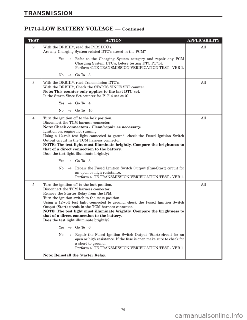
TEST ACTION APPLICABILITY
2 With the DRBIIIt, read the PCM DTC's.
Are any Charging System related DTC's stored in the PCM?All
Ye s®Refer to the Charging System category and repair any PCM
Charging System DTC's, before testing DTC P1714.
Perform 41TE TRANSMISSION VERIFICATION TEST - VER 1.
No®Go To 3
3 With the DRBIIIt, read Transmission DTC's.
With the DRBIIIt, Check the STARTS SINCE SET counter.
Note: This counter only applies to the last DTC set.
Is the Starts Since Set counter for P1714 set at 0?All
Ye s®Go To 4
No®Go To 10
4 Turn the ignition off to the lock position.
Disconnect the TCM harness connector.
Note: Check connectors - Clean/repair as necessary.
Ignition on, engine not running.
Using a 12-volt test light connected to ground, check the Fused Ignition Switch
Output circuit in the TCM harness connector.
NOTE: The test light must illuminate brightly. Compare the brightness to
that of a direct connection to the battery.
Does the test light illuminate brightly?All
Ye s®Go To 5
No®Repair the Fused Ignition Switch Output (Run/Start) circuit for
an open or high resistance.
Perform 41TE TRANSMISSION VERIFICATION TEST - VER 1.
5 Turn the ignition off to the lock position.
Disconnect the TCM harness connector.
Remove the Starter Relay from the IPM.
Turn the ignition switch to the start position.
Using a 12-volt test light connected to ground, check the Fused Ignition Switch
Output (Start) circuit in the TCM harness connector.
NOTE: The test light must illuminate brightly. Compare the brightness to
that of a direct connection to the battery.
Does the test light illuminate brightly?All
Ye s®Go To 6
No®Repair the Fused Ignition Switch Output (Start) circuit for an
open or high resistance. If the fuse is open make sure to check for
a short to ground.
Perform 41TE TRANSMISSION VERIFICATION TEST - VER 1.
Note: Reinstall the Starter Relay.
76
TRANSMISSION
P1714-LOW BATTERY VOLTAGE ÐContinued
Page 4181 of 4284
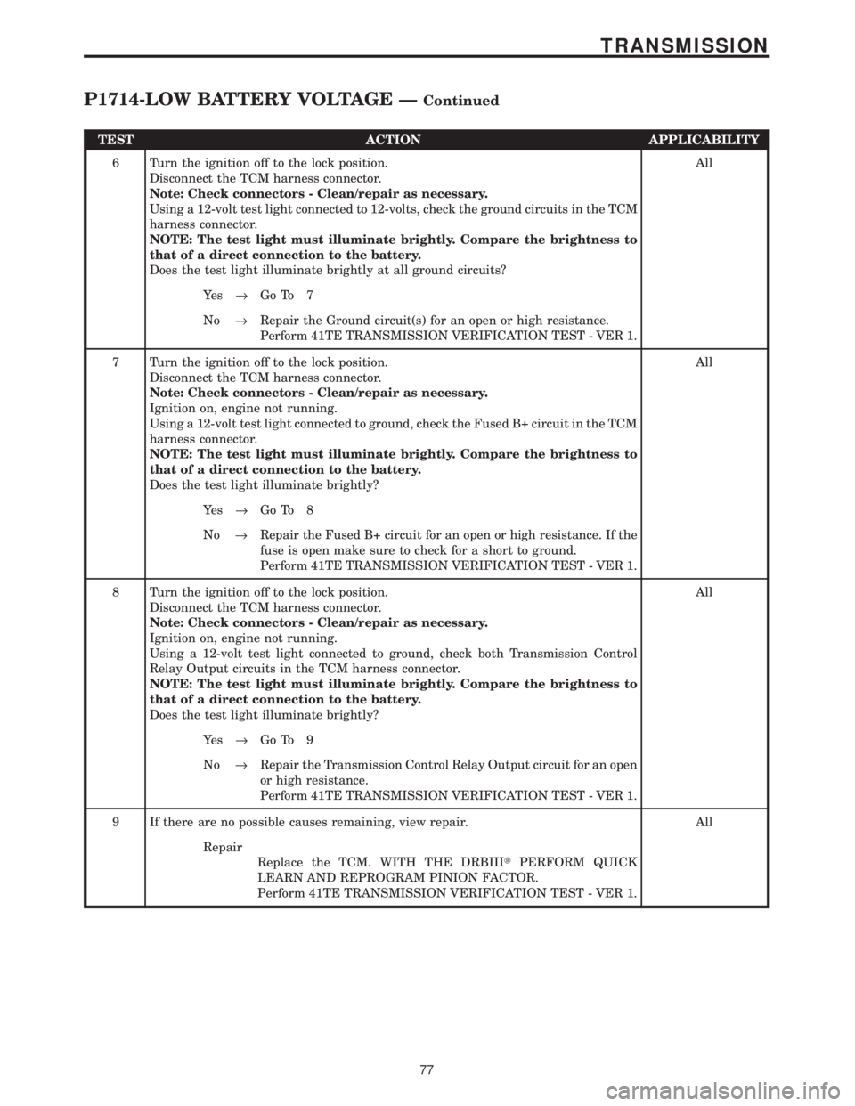
TEST ACTION APPLICABILITY
6 Turn the ignition off to the lock position.
Disconnect the TCM harness connector.
Note: Check connectors - Clean/repair as necessary.
Using a 12-volt test light connected to 12-volts, check the ground circuits in the TCM
harness connector.
NOTE: The test light must illuminate brightly. Compare the brightness to
that of a direct connection to the battery.
Does the test light illuminate brightly at all ground circuits?All
Ye s®Go To 7
No®Repair the Ground circuit(s) for an open or high resistance.
Perform 41TE TRANSMISSION VERIFICATION TEST - VER 1.
7 Turn the ignition off to the lock position.
Disconnect the TCM harness connector.
Note: Check connectors - Clean/repair as necessary.
Ignition on, engine not running.
Using a 12-volt test light connected to ground, check the Fused B+ circuit in the TCM
harness connector.
NOTE: The test light must illuminate brightly. Compare the brightness to
that of a direct connection to the battery.
Does the test light illuminate brightly?All
Ye s®Go To 8
No®Repair the Fused B+ circuit for an open or high resistance. If the
fuse is open make sure to check for a short to ground.
Perform 41TE TRANSMISSION VERIFICATION TEST - VER 1.
8 Turn the ignition off to the lock position.
Disconnect the TCM harness connector.
Note: Check connectors - Clean/repair as necessary.
Ignition on, engine not running.
Using a 12-volt test light connected to ground, check both Transmission Control
Relay Output circuits in the TCM harness connector.
NOTE: The test light must illuminate brightly. Compare the brightness to
that of a direct connection to the battery.
Does the test light illuminate brightly?All
Ye s®Go To 9
No®Repair the Transmission Control Relay Output circuit for an open
or high resistance.
Perform 41TE TRANSMISSION VERIFICATION TEST - VER 1.
9 If there are no possible causes remaining, view repair. All
Repair
Replace the TCM. WITH THE DRBIIItPERFORM QUICK
LEARN AND REPROGRAM PINION FACTOR.
Perform 41TE TRANSMISSION VERIFICATION TEST - VER 1.
77
TRANSMISSION
P1714-LOW BATTERY VOLTAGE ÐContinued