2001 CHRYSLER VOYAGER check engine light
[x] Cancel search: check engine lightPage 3804 of 4284
SYMPTOM DIAGNOSTIC TEST
POOR FUEL ECONOMY CHECKING PCM POWER AND GND CKT
CHECKING THE FUEL PRESSURE
CHECKING ECT SENSOR
CHECKING THROTTLE POSITION SENSOR
CHECKING MAP SENSOR
CHECKING IDLE AIR CONTROL MOTOR OPERATION
CHECKING IAT SENSOR
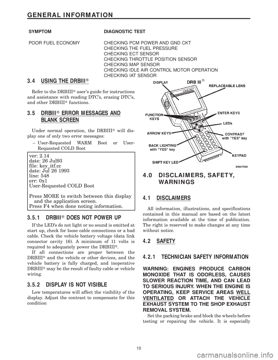
3.4 USING THE DRBIIIT
Refer to the DRBIIItuser 's guide for instructions
and assistance with reading DTC's, erasing DTC's,
and other DRBIIItfunctions.
3.5 DRBIIITERROR MESSAGES AND
BLANK SCREEN
Under normal operation, the DRBIIItwill dis-
play one of only two error messages:
± User-Requested WARM Boot or User-
Requested COLD Boot
ver: 2.14
date: 26 Jul93
file: key_itf.cc
date: Jul 26 1993
line: 548
err: 0x1
User-Requested COLD Boot
Press MORE to switch between this display
and the application screen.
Press F4 when done noting information.
3.5.1 DRBIIITDOES NOT POWER UP
If the LED's do not light or no sound is emitted at
start up, check for loose cable connections or a bad
cable. Check the vehicle battery voltage (data link
connector cavity 16). A minimum of 11 volts is
required to adequately power the DRBIIIt.
If all connections are proper between the
DRBIIItand the vehicle or other devices, and the
vehicle battery is fully charged, and inoperative
DRBIIItmay be the result of faulty cable or vehicle
wiring.
3.5.2 DISPLAY IS NOT VISIBLE
Low temperatures will affect the visibility of the
display. Adjust the contrast to compensate for this
condition
4.0 DISCLAIMERS, SAFETY,
WARNINGS
4.1 DISCLAIMERS
All information, illustrations, and specifications
contained in this manual are based on the latest
information available at the time of publication.
The right is reserved to make changes at any time
without notice.
4.2 SAFETY
4.2.1 TECHNICIAN SAFETY INFORMATION
WARNING: ENGINES PRODUCE CARBON
MONOXIDE THAT IS ODORLESS, CAUSES
SLOWER REACTION TIME, AND CAN LEAD
TO SERIOUS INJURY. WHEN THE ENGINE IS
OPERATING, KEEP SERVICE AREAS WELL
VENTILATED OR ATTACH THE VEHICLE
EXHAUST SYSTEM TO THE SHOP EXHAUST
REMOVAL SYSTEM.
Set the parking brake and block the wheels before
testing or repairing the vehicle. It is especially
10
GENERAL INFORMATION
Page 3812 of 4284
Symptom:
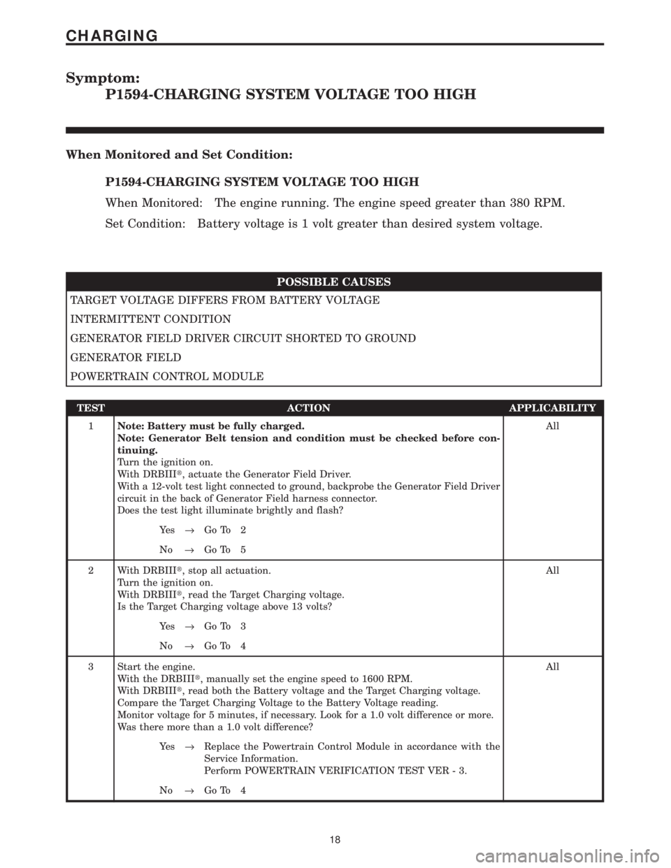
P1594-CHARGING SYSTEM VOLTAGE TOO HIGH
When Monitored and Set Condition:
P1594-CHARGING SYSTEM VOLTAGE TOO HIGH
When Monitored: The engine running. The engine speed greater than 380 RPM.
Set Condition: Battery voltage is 1 volt greater than desired system voltage.
POSSIBLE CAUSES
TARGET VOLTAGE DIFFERS FROM BATTERY VOLTAGE
INTERMITTENT CONDITION
GENERATOR FIELD DRIVER CIRCUIT SHORTED TO GROUND
GENERATOR FIELD
POWERTRAIN CONTROL MODULE
TEST ACTION APPLICABILITY
1Note: Battery must be fully charged.
Note: Generator Belt tension and condition must be checked before con-
tinuing.
Turn the ignition on.
With DRBIIIt, actuate the Generator Field Driver.
With a 12-volt test light connected to ground, backprobe the Generator Field Driver
circuit in the back of Generator Field harness connector.
Does the test light illuminate brightly and flash?All
Ye s®Go To 2
No®Go To 5
2 With DRBIIIt, stop all actuation.
Turn the ignition on.
With DRBIIIt, read the Target Charging voltage.
Is the Target Charging voltage above 13 volts?All
Ye s®Go To 3
No®Go To 4
3 Start the engine.
With the DRBIIIt, manually set the engine speed to 1600 RPM.
With DRBIIIt, read both the Battery voltage and the Target Charging voltage.
Compare the Target Charging Voltage to the Battery Voltage reading.
Monitor voltage for 5 minutes, if necessary. Look for a 1.0 volt difference or more.
Was there more than a 1.0 volt difference?All
Ye s®Replace the Powertrain Control Module in accordance with the
Service Information.
Perform POWERTRAIN VERIFICATION TEST VER - 3.
No®Go To 4
18
CHARGING
Page 3972 of 4284
Symptom:
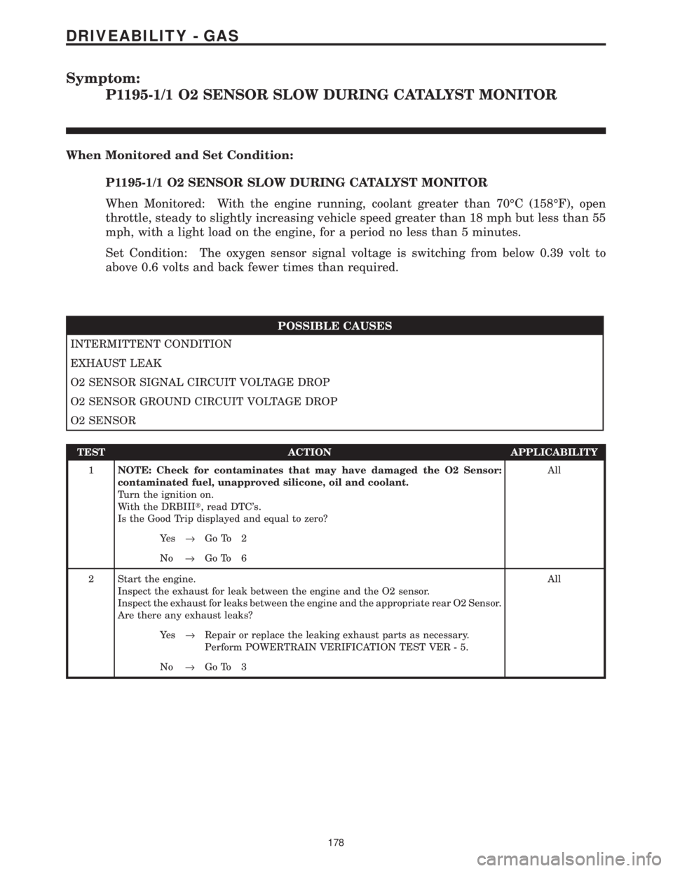
P1195-1/1 O2 SENSOR SLOW DURING CATALYST MONITOR
When Monitored and Set Condition:
P1195-1/1 O2 SENSOR SLOW DURING CATALYST MONITOR
When Monitored: With the engine running, coolant greater than 70ÉC (158ÉF), open
throttle, steady to slightly increasing vehicle speed greater than 18 mph but less than 55
mph, with a light load on the engine, for a period no less than 5 minutes.
Set Condition: The oxygen sensor signal voltage is switching from below 0.39 volt to
above 0.6 volts and back fewer times than required.
POSSIBLE CAUSES
INTERMITTENT CONDITION
EXHAUST LEAK
O2 SENSOR SIGNAL CIRCUIT VOLTAGE DROP
O2 SENSOR GROUND CIRCUIT VOLTAGE DROP
O2 SENSOR
TEST ACTION APPLICABILITY
1NOTE: Check for contaminates that may have damaged the O2 Sensor:
contaminated fuel, unapproved silicone, oil and coolant.
Turn the ignition on.
With the DRBIIIt, read DTC's.
Is the Good Trip displayed and equal to zero?All
Ye s®Go To 2
No®Go To 6
2 Start the engine.
Inspect the exhaust for leak between the engine and the O2 sensor.
Inspect the exhaust for leaks between the engine and the appropriate rear O2 Sensor.
Are there any exhaust leaks?All
Ye s®Repair or replace the leaking exhaust parts as necessary.
Perform POWERTRAIN VERIFICATION TEST VER - 5.
No®Go To 3
178
DRIVEABILITY - GAS
Page 3980 of 4284
TEST ACTION APPLICABILITY
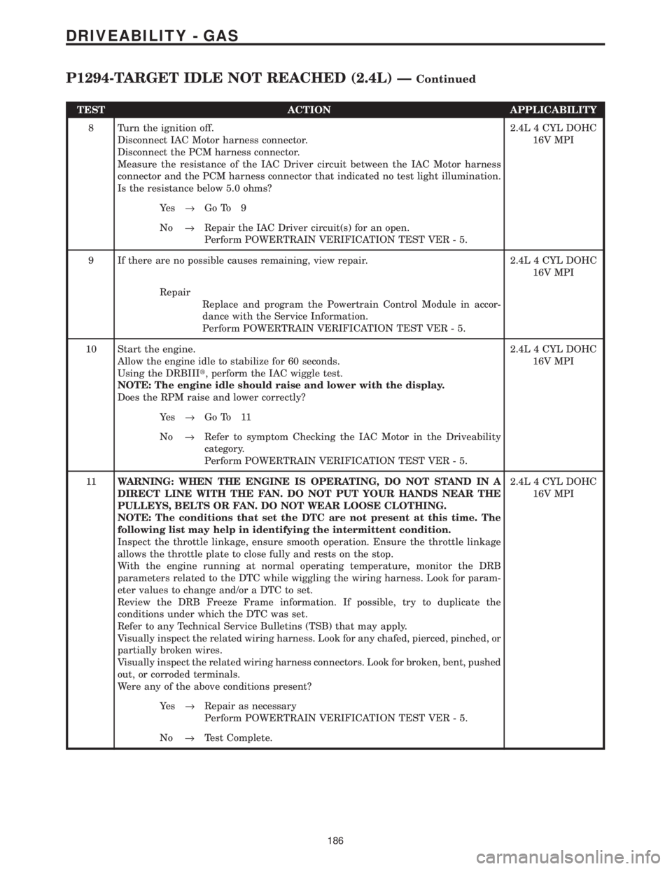
8 Turn the ignition off.
Disconnect IAC Motor harness connector.
Disconnect the PCM harness connector.
Measure the resistance of the IAC Driver circuit between the IAC Motor harness
connector and the PCM harness connector that indicated no test light illumination.
Is the resistance below 5.0 ohms?2.4L 4 CYL DOHC
16V MPI
Ye s®Go To 9
No®Repair the IAC Driver circuit(s) for an open.
Perform POWERTRAIN VERIFICATION TEST VER - 5.
9 If there are no possible causes remaining, view repair. 2.4L 4 CYL DOHC
16V MPI
Repair
Replace and program the Powertrain Control Module in accor-
dance with the Service Information.
Perform POWERTRAIN VERIFICATION TEST VER - 5.
10 Start the engine.
Allow the engine idle to stabilize for 60 seconds.
Using the DRBIIIt, perform the IAC wiggle test.
NOTE: The engine idle should raise and lower with the display.
Does the RPM raise and lower correctly?2.4L 4 CYL DOHC
16V MPI
Ye s®Go To 11
No®Refer to symptom Checking the IAC Motor in the Driveability
category.
Perform POWERTRAIN VERIFICATION TEST VER - 5.
11WARNING: WHEN THE ENGINE IS OPERATING, DO NOT STAND IN A
DIRECT LINE WITH THE FAN. DO NOT PUT YOUR HANDS NEAR THE
PULLEYS, BELTS OR FAN. DO NOT WEAR LOOSE CLOTHING.
NOTE: The conditions that set the DTC are not present at this time. The
following list may help in identifying the intermittent condition.
Inspect the throttle linkage, ensure smooth operation. Ensure the throttle linkage
allows the throttle plate to close fully and rests on the stop.
With the engine running at normal operating temperature, monitor the DRB
parameters related to the DTC while wiggling the wiring harness. Look for param-
eter values to change and/or a DTC to set.
Review the DRB Freeze Frame information. If possible, try to duplicate the
conditions under which the DTC was set.
Refer to any Technical Service Bulletins (TSB) that may apply.
Visually inspect the related wiring harness. Look for any chafed, pierced, pinched, or
partially broken wires.
Visually inspect the related wiring harness connectors. Look for broken, bent, pushed
out, or corroded terminals.
Were any of the above conditions present?2.4L 4 CYL DOHC
16V MPI
Ye s®Repair as necessary
Perform POWERTRAIN VERIFICATION TEST VER - 5.
No®Test Complete.
186
DRIVEABILITY - GAS
P1294-TARGET IDLE NOT REACHED (2.4L) ÐContinued
Page 4005 of 4284
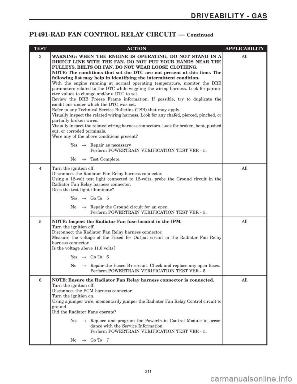
TEST ACTION APPLICABILITY
3WARNING: WHEN THE ENGINE IS OPERATING, DO NOT STAND IN A
DIRECT LINE WITH THE FAN. DO NOT PUT YOUR HANDS NEAR THE
PULLEYS, BELTS OR FAN. DO NOT WEAR LOOSE CLOTHING.
NOTE: The conditions that set the DTC are not present at this time. The
following list may help in identifying the intermittent condition.
With the engine running at normal operating temperature, monitor the DRB
parameters related to the DTC while wiggling the wiring harness. Look for param-
eter values to change and/or a DTC to set.
Review the DRB Freeze Frame information. If possible, try to duplicate the
conditions under which the DTC was set.
Refer to any Technical Service Bulletins (TSB) that may apply.
Visually inspect the related wiring harness. Look for any chafed, pierced, pinched, or
partially broken wires.
Visually inspect the related wiring harness connectors. Look for broken, bent, pushed
out, or corroded terminals.
Were any of the above conditions present?All
Ye s®Repair as necessary
Perform POWERTRAIN VERIFICATION TEST VER - 5.
No®Test Complete.
4 Turn the ignition off.
Disconnect the Radiator Fan Relay harness connector.
Using a 12-volt test light connected to 12-volts, probe the Ground circuit in the
Radiator Fan Relay harness connector.
Does the test light illuminate?All
Ye s®Go To 5
No®Repair the Ground circuit for an open.
Perform POWERTRAIN VERIFICATION TEST VER - 5.
5NOTE: Inspect the Radiator Fan fuse located in the IPM.
Turn the ignition off.
Disconnect the Radiator Fan Relay harness connector.
Measure the voltage of the Fused B+ Output circuit in the Radiator Fan Relay
harness connector.
Is the voltage above 11.0 volts?All
Ye s®Go To 6
No®Repair the Fused B+ circuit. Check and replace any open fuses.
Perform POWERTRAIN VERIFICATION TEST VER - 5.
6NOTE: Ensure the Radiator Fan Relay harness connector is connected.
Turn the ignition off.
Disconnect the PCM harness connector.
Turn the ignition on.
Using a jumper wire, momentarily jumper the Radiator Fan Relay Control circuit to
ground.
Did the Radiator Fans operate?All
Ye s®Replace and program the Powertrain Control Module in accor-
dance with the Service Information.
Perform POWERTRAIN VERIFICATION TEST VER - 5.
No®Go To 7
211
DRIVEABILITY - GAS
P1491-RAD FAN CONTROL RELAY CIRCUIT ÐContinued
Page 4023 of 4284
TEST ACTION APPLICABILITY
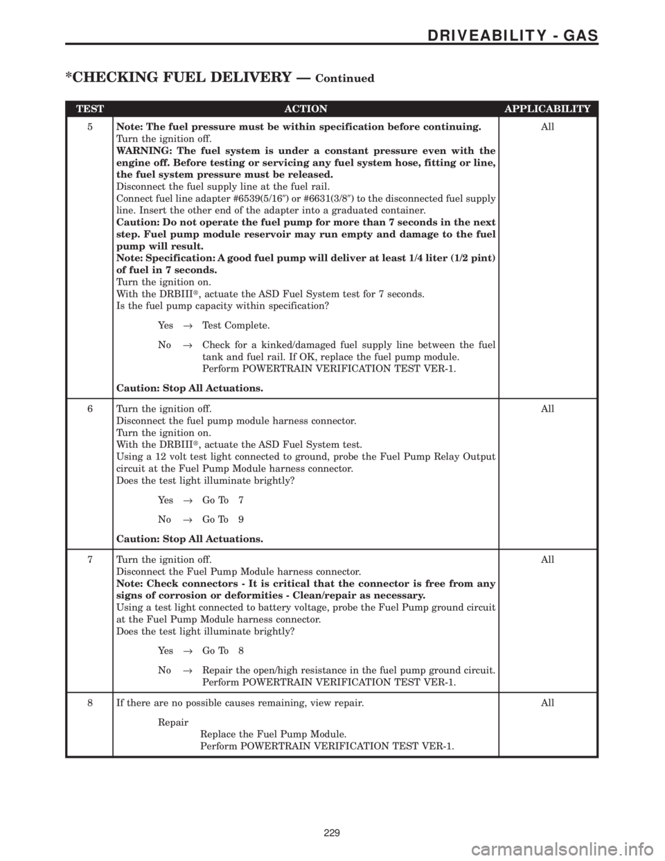
5Note: The fuel pressure must be within specification before continuing.
Turn the ignition off.
WARNING: The fuel system is under a constant pressure even with the
engine off. Before testing or servicing any fuel system hose, fitting or line,
the fuel system pressure must be released.
Disconnect the fuel supply line at the fuel rail.
Connect fuel line adapter #6539(5/169) or #6631(3/89) to the disconnected fuel supply
line. Insert the other end of the adapter into a graduated container.
Caution: Do not operate the fuel pump for more than 7 seconds in the next
step. Fuel pump module reservoir may run empty and damage to the fuel
pump will result.
Note: Specification: A good fuel pump will deliver at least 1/4 liter (1/2 pint)
of fuel in 7 seconds.
Turn the ignition on.
With the DRBIIIt, actuate the ASD Fuel System test for 7 seconds.
Is the fuel pump capacity within specification?All
Ye s®Test Complete.
No®Check for a kinked/damaged fuel supply line between the fuel
tank and fuel rail. If OK, replace the fuel pump module.
Perform POWERTRAIN VERIFICATION TEST VER-1.
Caution: Stop All Actuations.
6 Turn the ignition off.
Disconnect the fuel pump module harness connector.
Turn the ignition on.
With the DRBIIIt, actuate the ASD Fuel System test.
Using a 12 volt test light connected to ground, probe the Fuel Pump Relay Output
circuit at the Fuel Pump Module harness connector.
Does the test light illuminate brightly?All
Ye s®Go To 7
No®Go To 9
Caution: Stop All Actuations.
7 Turn the ignition off.
Disconnect the Fuel Pump Module harness connector.
Note: Check connectors - It is critical that the connector is free from any
signs of corrosion or deformities - Clean/repair as necessary.
Using a test light connected to battery voltage, probe the Fuel Pump ground circuit
at the Fuel Pump Module harness connector.
Does the test light illuminate brightly?All
Ye s®Go To 8
No®Repair the open/high resistance in the fuel pump ground circuit.
Perform POWERTRAIN VERIFICATION TEST VER-1.
8 If there are no possible causes remaining, view repair. All
Repair
Replace the Fuel Pump Module.
Perform POWERTRAIN VERIFICATION TEST VER-1.
229
DRIVEABILITY - GAS
*CHECKING FUEL DELIVERY ÐContinued
Page 4050 of 4284

TEST ACTION APPLICABILITY
8 The following items need to be checked as a possible cause for a no start condition.
Refer to any Technical Service Bulletins that may apply to the symptom.
The spark plugs must be free from fuel, oil, coolant and/or any foreign material or
deposits.
The fuel must be free from contamination.
The exhaust may be free from restrictions.
The engine compression must be within specifications.
The engine valve timing must be within specifications.
The engine must be free from vacuum leaks.
Were any of the above conditions found?All
Ye s®Repair as necessary.
Perform POWERTRAIN VERIFICATION TEST VER-1.
No®Test Complete.
9 Turn the ignition off.
Disconnect the fuel pump module harness connector.
Turn the ignition on.
With the DRBIIIt, actuate the ASD Fuel System test.
Using a 12 volt test light connected to ground, probe the Fuel Pump Relay Output
circuit at the Fuel Pump Module harness connector.
Does the test light illuminate brightly?All
Ye s®Go To 10
No®Go To 12
Caution: Stop All Actuations.
10 Turn the ignition off.
Disconnect the Fuel Pump Module harness connector.
Note: Check connectors - It is critical that the connector is free from any
signs of corrosion or deformities - Clean/repair as necessary.
Using a test light connected to battery voltage, probe the Fuel Pump ground circuit
at the Fuel Pump Module harness connector.
Does the test light illuminate brightly?All
Ye s®Go To 11
No®Repair the open/high resistance in the fuel pump ground circuit.
Perform POWERTRAIN VERIFICATION TEST VER-1.
11 If there are no possible causes remaining, view repair. All
Repair
Replace the Fuel Pump Module.
Perform POWERTRAIN VERIFICATION TEST VER-1.
12 Turn the ignition off.
Remove the Fuel Pump Relay from the IPM.
With a 12 volt test light connected to ground, probe the Fuel Pump Relay Fused B+
circuit in the IPM.
Does the test light illuminate?All
Ye s®Go To 13
No®Check for an open Fuel Pump fuse, repair cause of open. If OK,
replace the IPM Fuse & Relay Center.
Perform POWERTRAIN VERIFICATION TEST VER-1.
256
STARTING
*ENGINE CRANKS DOES NOT START ÐContinued
Page 4069 of 4284
VERIFICATION TESTS
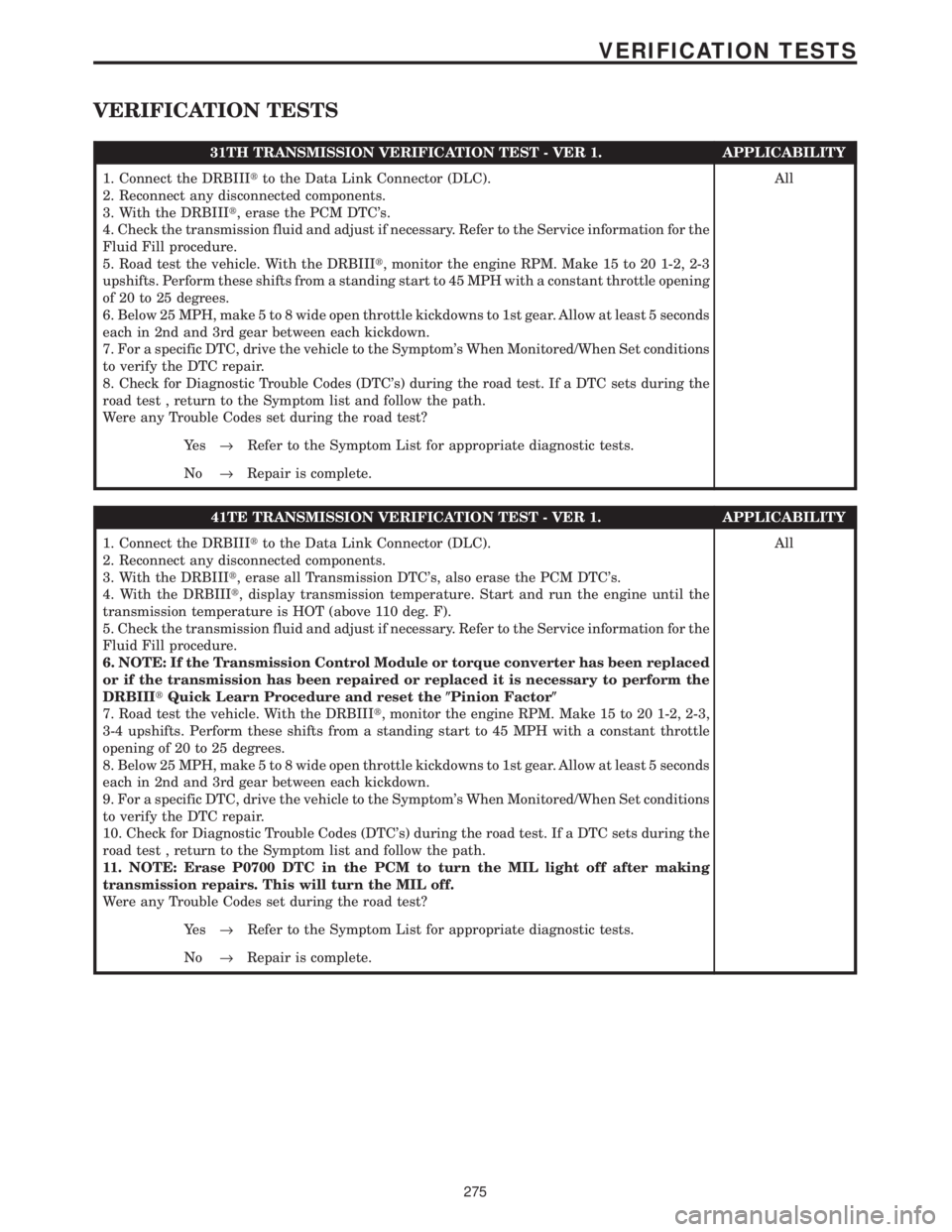
31TH TRANSMISSION VERIFICATION TEST - VER 1. APPLICABILITY
1. Connect the DRBIIItto the Data Link Connector (DLC).
2. Reconnect any disconnected components.
3. With the DRBIIIt, erase the PCM DTC's.
4. Check the transmission fluid and adjust if necessary. Refer to the Service information for the
Fluid Fill procedure.
5. Road test the vehicle. With the DRBIIIt, monitor the engine RPM. Make 15 to 20 1-2, 2-3
upshifts. Perform these shifts from a standing start to 45 MPH with a constant throttle opening
of 20 to 25 degrees.
6. Below 25 MPH, make 5 to 8 wide open throttle kickdowns to 1st gear. Allow at least 5 seconds
each in 2nd and 3rd gear between each kickdown.
7. For a specific DTC, drive the vehicle to the Symptom's When Monitored/When Set conditions
to verify the DTC repair.
8. Check for Diagnostic Trouble Codes (DTC's) during the road test. If a DTC sets during the
road test , return to the Symptom list and follow the path.
Were any Trouble Codes set during the road test?All
Ye s®Refer to the Symptom List for appropriate diagnostic tests.
No®Repair is complete.
41TE TRANSMISSION VERIFICATION TEST - VER 1. APPLICABILITY
1. Connect the DRBIIItto the Data Link Connector (DLC).
2. Reconnect any disconnected components.
3. With the DRBIIIt, erase all Transmission DTC's, also erase the PCM DTC's.
4. With the DRBIIIt, display transmission temperature. Start and run the engine until the
transmission temperature is HOT (above 110 deg. F).
5. Check the transmission fluid and adjust if necessary. Refer to the Service information for the
Fluid Fill procedure.
6. NOTE: If the Transmission Control Module or torque converter has been replaced
or if the transmission has been repaired or replaced it is necessary to perform the
DRBIIItQuick Learn Procedure and reset the(Pinion Factor(
7. Road test the vehicle. With the DRBIIIt, monitor the engine RPM. Make 15 to 20 1-2, 2-3,
3-4 upshifts. Perform these shifts from a standing start to 45 MPH with a constant throttle
opening of 20 to 25 degrees.
8. Below 25 MPH, make 5 to 8 wide open throttle kickdowns to 1st gear. Allow at least 5 seconds
each in 2nd and 3rd gear between each kickdown.
9. For a specific DTC, drive the vehicle to the Symptom's When Monitored/When Set conditions
to verify the DTC repair.
10. Check for Diagnostic Trouble Codes (DTC's) during the road test. If a DTC sets during the
road test , return to the Symptom list and follow the path.
11. NOTE: Erase P0700 DTC in the PCM to turn the MIL light off after making
transmission repairs. This will turn the MIL off.
Were any Trouble Codes set during the road test?All
Ye s®Refer to the Symptom List for appropriate diagnostic tests.
No®Repair is complete.
275
VERIFICATION TESTS