2001 CHRYSLER VOYAGER fuses
[x] Cancel search: fusesPage 25 of 4284
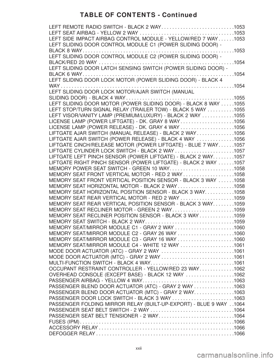
TABLE OF CONTENTS - Continued
LEFT REMOTE RADIO SWITCH - BLACK 2 WAY...........................1053
LEFT SEAT AIRBAG - YELLOW 2 WAY...................................1053
LEFT SIDE IMPACT AIRBAG CONTROL MODULE - YELLOW/RED 7 WAY......1053
LEFT SLIDING DOOR CONTROL MODULE C1 (POWER SLIDING DOOR) -
BLACK 8 WAY........................................................1053
LEFT SLIDING DOOR CONTROL MODULE C2 (POWER SLIDING DOOR) -
BLACK/RED 20 WAY..................................................1054
LEFT SLIDING DOOR LATCH SENSING SWITCH (POWER SLIDING DOOR) -
BLACK 6 WAY........................................................1054
LEFT SLIDING DOOR LOCK MOTOR (POWER SLIDING DOOR) - BLACK 4
WAY................................................................1054
LEFT SLIDING DOOR LOCK MOTOR/AJAR SWITCH (MANUAL
SLIDING DOOR) - BLACK 4 WAY........................................1055
LEFT SLIDING DOOR MOTOR (POWER SLIDING DOOR) - BLACK 8 WAY.....1055
LEFT STOP/TURN SIGNAL RELAY (TRAILER TOW) - BLACK 5 WAY..........1055
LEFT VISOR/VANITY LAMP (PREMIUM/LUXURY) - BLACK 2 WAY............1055
LICENSE LAMP (POWER LIFTGATE) - DK. GRAY 8 WAY....................1056
LICENSE LAMP (POWER RELEASE) - DK. GRAY 4 WAY....................1056
LIFTGATE AJAR SWITCH (MANUAL RELEASE) - BLACK 2 WAY..............1056
LIFTGATE AJAR SWITCH (POWER RELEASE) - BLACK 4 WAY..............1056
LIFTGATE CINCH/RELEASE MOTOR (POWER LIFTGATE) - BLUE 7 WAY......1057
LIFTGATE CYLINDER LOCK SWITCH - BLACK 2 WAY......................1057
LIFTGATE LEFT PINCH SENSOR (POWER LIFTGATE) - BLACK 2 WAY........1057
LIFTGATE RIGHT PINCH SENSOR (POWER LIFTGATE) - BLACK 2 WAY......1057
MEMORY POWER SEAT SWITCH - GREEN 10 WAY........................1058
MEMORY SEAT FRONT VERTICAL MOTOR - RED 2 WAY...................1058
MEMORY SEAT FRONT VERTICAL POSITION SENSOR - BLACK 3 WAY......1058
MEMORY SEAT HORIZONTAL MOTOR - BLACK 2 WAY.....................1058
MEMORY SEAT HORIZONTAL POSITION SENSOR - BLACK 3 WAY...........1058
MEMORY SEAT REAR VERTICAL MOTOR - RED 2 WAY....................1059
MEMORY SEAT REAR VERTICAL POSITION SENSOR - BLACK 3 WAY........1059
MEMORY SEAT RECLINER MOTOR - GREEN 2 WAY.......................1059
MEMORY SEAT RECLINER POSITION SENSOR - BLACK 3 WAY.............1059
MEMORY SEAT SWITCH - BLACK 2 WAY.................................1059
MEMORY SEAT/MIRROR MODULE C1 - GRAY 2 WAY......................1060
MEMORY SEAT/MIRROR MODULE C2 - GRAY 26 WAY.....................1060
MEMORY SEAT/MIRROR MODULE C3 - GRAY 16 WAY.....................1060
MEMORY SEAT/MIRROR MODULE C4 - WHITE 12 WAY....................1061
MODE DOOR ACTUATOR (ATC) - GRAY 2 WAY...........................1061
MODE DOOR ACTUATOR (MTC) - GRAY 2 WAY...........................1061
MULTI-FUNCTION SWITCH - BLACK 4 WAY...............................1061
OCCUPANT RESTRAINT CONTROLLER - YELLOW/RED 23 WAY.............1062
OVERHEAD CONSOLE (EXCEPT BASE) - BLACK 12 WAY..................1062
PASSENGER AIRBAG - YELLOW 4 WAY..................................1063
PASSENGER BLEND DOOR ACTUATOR (ATC) - GRAY 2 WAY...............1063
PASSENGER BLEND DOOR ACTUATOR (MTC) - GRAY 2 WAY...............1063
PASSENGER DOOR LOCK SWITCH - BLACK 3 WAY.......................1063
PASSENGER FOLDING MIRROR RELAY (BUILT-UP-EXPORT) - BLUE 9 WAY . .1064
PASSENGER SEAT BELT SWITCH-2WAY...............................1064
PASSENGER SEAT BELT TENSIONER-2WAY............................1064
FUSES (IPM).........................................................1066
ACCESSORY RELAY..................................................1066
DEFOGGER RELAY...................................................1066
xxii
Page 42 of 4284
3.7.6 EXTERIOR LIGHTING BATTERY
SAVER
The BCM monitors the status of, and controls, the
Park Lamps, Headlamps and Fog Lamp relays. If
any exterior lamps are left ON after the ignition is
turned OFF, the BCM will turn them OFF after 3
minutes.
3.7.7 AUTO HEADLAMPS
This feature is available on vehicles equipped
with both the Electrocromatic Mirror (ECM) and
the Compass/Mini-Trip Computer (CMTC). When
the BCM detects a day/night signal from the CMTC,
an ECM is present and Auto Headlamp mode is
selected.
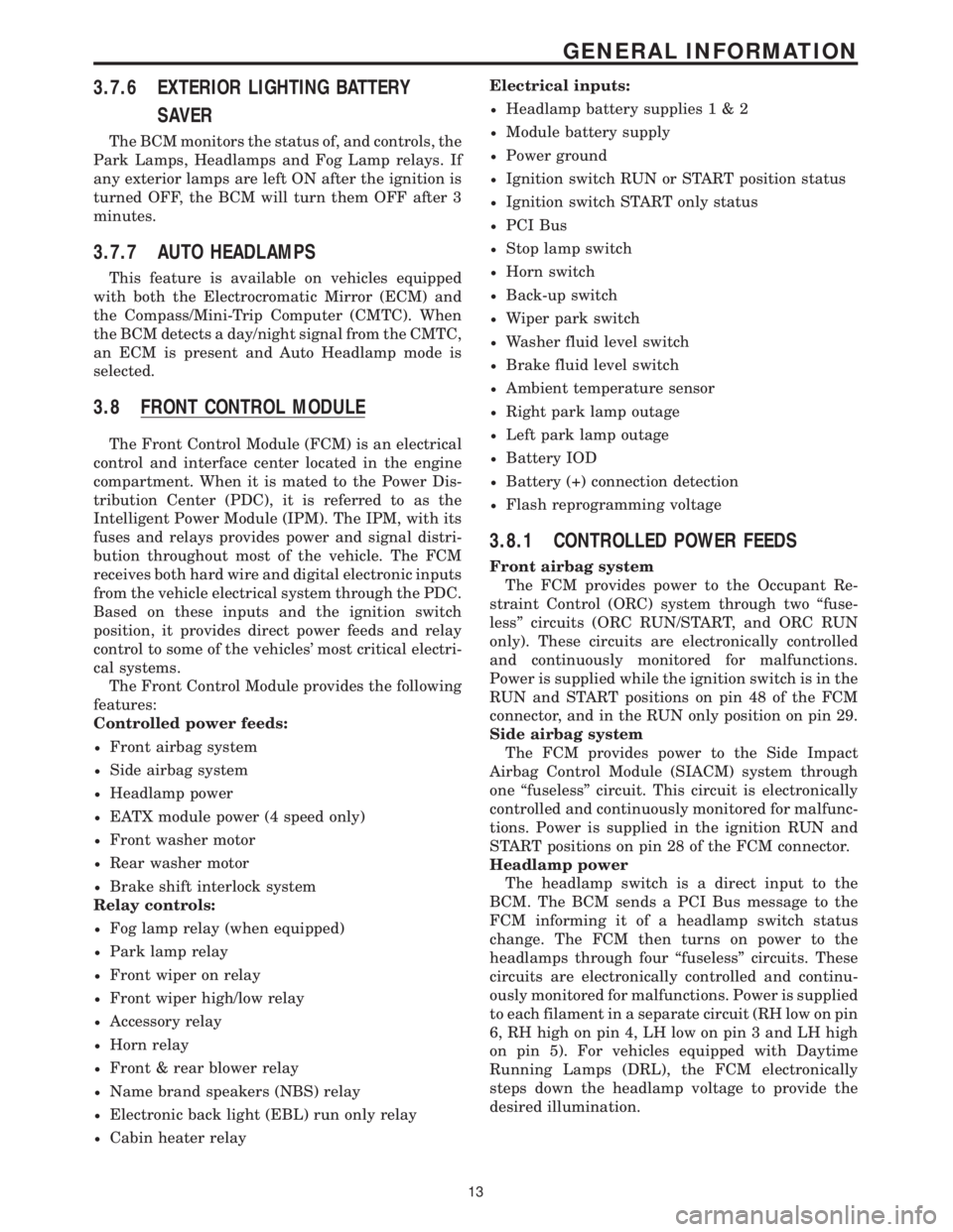
3.8 FRONT CONTROL MODULE
The Front Control Module (FCM) is an electrical
control and interface center located in the engine
compartment. When it is mated to the Power Dis-
tribution Center (PDC), it is referred to as the
Intelligent Power Module (IPM). The IPM, with its
fuses and relays provides power and signal distri-
bution throughout most of the vehicle. The FCM
receives both hard wire and digital electronic inputs
from the vehicle electrical system through the PDC.
Based on these inputs and the ignition switch
position, it provides direct power feeds and relay
control to some of the vehicles' most critical electri-
cal systems.
The Front Control Module provides the following
features:
Controlled power feeds:
²Front airbag system
²Side airbag system
²Headlamp power
²EATX module power (4 speed only)
²Front washer motor
²Rear washer motor
²Brake shift interlock system
Relay controls:
²Fog lamp relay (when equipped)
²Park lamp relay
²Front wiper on relay
²Front wiper high/low relay
²Accessory relay
²Horn relay
²Front & rear blower relay
²Name brand speakers (NBS) relay
²Electronic back light (EBL) run only relay
²Cabin heater relayElectrical inputs:
²Headlamp battery supplies1&2
²Module battery supply
²Power ground
²Ignition switch RUN or START position status
²Ignition switch START only status
²PCI Bus
²Stop lamp switch
²Horn switch
²Back-up switch
²Wiper park switch
²Washer fluid level switch
²Brake fluid level switch
²Ambient temperature sensor
²Right park lamp outage
²Left park lamp outage
²Battery IOD
²Battery (+) connection detection
²Flash reprogramming voltage
3.8.1 CONTROLLED POWER FEEDS
Front airbag system
The FCM provides power to the Occupant Re-
straint Control (ORC) system through two ªfuse-
lessº circuits (ORC RUN/START, and ORC RUN
only). These circuits are electronically controlled
and continuously monitored for malfunctions.
Power is supplied while the ignition switch is in the
RUN and START positions on pin 48 of the FCM
connector, and in the RUN only position on pin 29.
Side airbag system
The FCM provides power to the Side Impact
Airbag Control Module (SIACM) system through
one ªfuselessº circuit. This circuit is electronically
controlled and continuously monitored for malfunc-
tions. Power is supplied in the ignition RUN and
START positions on pin 28 of the FCM connector.
Headlamp power
The headlamp switch is a direct input to the
BCM. The BCM sends a PCI Bus message to the
FCM informing it of a headlamp switch status
change. The FCM then turns on power to the
headlamps through four ªfuselessº circuits. These
circuits are electronically controlled and continu-
ously monitored for malfunctions. Power is supplied
to each filament in a separate circuit (RH low on pin
6, RH high on pin 4, LH low on pin 3 and LH high
on pin 5). For vehicles equipped with Daytime
Running Lamps (DRL), the FCM electronically
steps down the headlamp voltage to provide the
desired illumination.
13
GENERAL INFORMATION
Page 58 of 4284
When diagnosing a chassis system problem, it is
important to follow approved procedures where
applicable. These procedures can be found in this
General Information Section or in the service man-
ual procedures. Following these procedures is very
important to safety of individuals performing diag-
nostic tests.
4.2.2 VEHICLE PREPARATION FOR
TESTING
Make sure the vehicle being tested has a fully
charged battery. If it does not, false diagnostic codes
or error messages may occur.
4.2.3 SERVICING SUB-ASSEMBLIES
Some components of the chassis system are in-
tended to be serviced as an assembly only. Attempt-
ing to remove or repair certain system sub-
components may result in personal injury and/or
improper system operation. Only those components
with approved repair and installation procedures in
the service manual should be serviced.
4.2.4 DRBIIITSAFETY INFORMATION
WARNING: EXCEEDING THE LIMITS OF THE
DRBIIITMULTIMETER IS DANGEROUS. IT
CAN EXPOSE YOU TO SERIOUS OR
POSSIBLY FATAL INJURY. CAREFULLY
READ AND UNDERSTAND THE CAUTIONS
AND THE SPECIFICATION LIMITS.
²Follow the vehicle manufacturer 's service speci-
fications at all times.
²Do not use the DRBIIItif it has been damaged.
²Do not use the test leads if the insulation is
damaged or if metal is exposed.
²To avoid electrical shock, do not touch the test
leads, tips, or the circuit being tested.
²Choose the proper range and functions for the
measurement. Do not try voltage or current mea-
surement that may exceed the rated capacity.
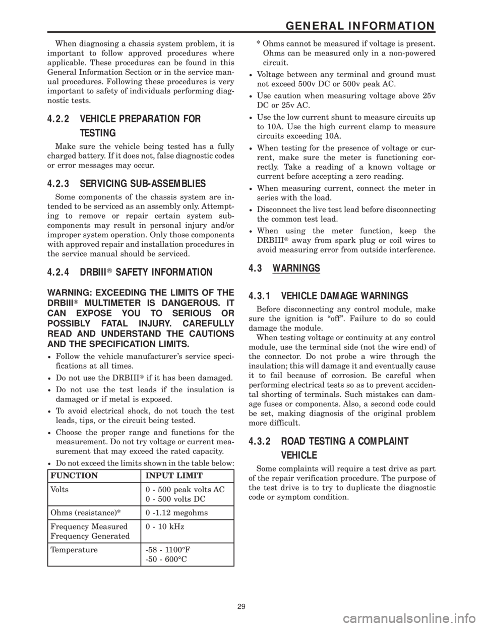
²Do not exceed the limits shown in the table below:
FUNCTION INPUT LIMIT
Volts 0 - 500 peak volts AC
0 - 500 volts DC
Ohms (resistance)* 0 -1.12 megohms
Frequency Measured
Frequency Generated0-10kHz
Temperature -58 - 1100ÉF
-50 - 600ÉC* Ohms cannot be measured if voltage is present.
Ohms can be measured only in a non-powered
circuit.
²Voltage between any terminal and ground must
not exceed 500v DC or 500v peak AC.
²Use caution when measuring voltage above 25v
DC or 25v AC.
²Use the low current shunt to measure circuits up
to 10A. Use the high current clamp to measure
circuits exceeding 10A.
²When testing for the presence of voltage or cur-
rent, make sure the meter is functioning cor-
rectly. Take a reading of a known voltage or
current before accepting a zero reading.
²When measuring current, connect the meter in
series with the load.
²Disconnect the live test lead before disconnecting
the common test lead.
²When using the meter function, keep the
DRBIIItaway from spark plug or coil wires to
avoid measuring error from outside interference.
4.3 WARNINGS
4.3.1 VEHICLE DAMAGE WARNINGS
Before disconnecting any control module, make
sure the ignition is ªoffº. Failure to do so could
damage the module.
When testing voltage or continuity at any control
module, use the terminal side (not the wire end) of
the connector. Do not probe a wire through the
insulation; this will damage it and eventually cause
it to fail because of corrosion. Be careful when
performing electrical tests so as to prevent acciden-
tal shorting of terminals. Such mistakes can dam-
age fuses or components. Also, a second code could
be set, making diagnosis of the original problem
more difficult.
4.3.2 ROAD TESTING A COMPLAINT
VEHICLE
Some complaints will require a test drive as part
of the repair verification procedure. The purpose of
the test drive is to try to duplicate the diagnostic
code or symptom condition.
29
GENERAL INFORMATION
Page 1095 of 4284
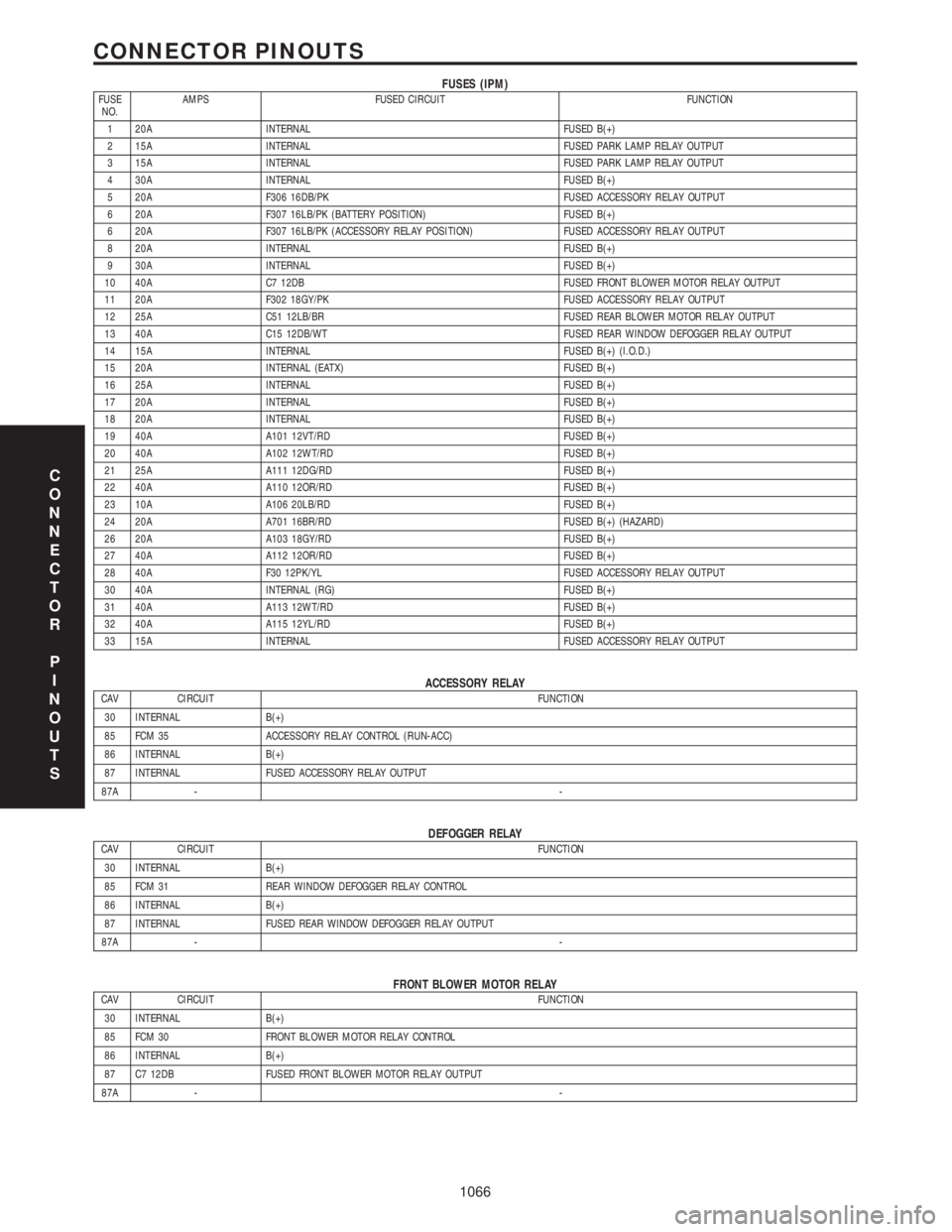
FUSES (IPM)FUSE
NO.AMPS FUSED CIRCUIT FUNCTION
1 20A INTERNAL FUSED B(+)
2 15A INTERNAL FUSED PARK LAMP RELAY OUTPUT
3 15A INTERNAL FUSED PARK LAMP RELAY OUTPUT
4 30A INTERNAL FUSED B(+)
5 20A F306 16DB/PK FUSED ACCESSORY RELAY OUTPUT
6 20A F307 16LB/PK (BATTERY POSITION) FUSED B(+)
6 20A F307 16LB/PK (ACCESSORY RELAY POSITION) FUSED ACCESSORY RELAY OUTPUT
8 20A INTERNAL FUSED B(+)
9 30A INTERNAL FUSED B(+)
10 40A C7 12DB FUSED FRONT BLOWER MOTOR RELAY OUTPUT
11 20A F302 18GY/PK FUSED ACCESSORY RELAY OUTPUT
12 25A C51 12LB/BR FUSED REAR BLOWER MOTOR RELAY OUTPUT
13 40A C15 12DB/WT FUSED REAR WINDOW DEFOGGER RELAY OUTPUT
14 15A INTERNAL FUSED B(+) (I.O.D.)
15 20A INTERNAL (EATX) FUSED B(+)
16 25A INTERNAL FUSED B(+)
17 20A INTERNAL FUSED B(+)
18 20A INTERNAL FUSED B(+)
19 40A A101 12VT/RD FUSED B(+)
20 40A A102 12WT/RD FUSED B(+)
21 25A A111 12DG/RD FUSED B(+)
22 40A A110 12OR/RD FUSED B(+)
23 10A A106 20LB/RD FUSED B(+)
24 20A A701 16BR/RD FUSED B(+) (HAZARD)
26 20A A103 18GY/RD FUSED B(+)
27 40A A112 12OR/RD FUSED B(+)
28 40A F30 12PK/YL FUSED ACCESSORY RELAY OUTPUT
30 40A INTERNAL (RG) FUSED B(+)
31 40A A113 12WT/RD FUSED B(+)
32 40A A115 12YL/RD FUSED B(+)
33 15A INTERNAL FUSED ACCESSORY RELAY OUTPUT
ACCESSORY RELAYCAV CIRCUIT FUNCTION
30 INTERNAL B(+)
85 FCM 35 ACCESSORY RELAY CONTROL (RUN-ACC)
86 INTERNAL B(+)
87 INTERNAL FUSED ACCESSORY RELAY OUTPUT
87A --
DEFOGGER RELAYCAV CIRCUIT FUNCTION
30 INTERNAL B(+)
85 FCM 31 REAR WINDOW DEFOGGER RELAY CONTROL
86 INTERNAL B(+)
87 INTERNAL FUSED REAR WINDOW DEFOGGER RELAY OUTPUT
87A --
FRONT BLOWER MOTOR RELAYCAV CIRCUIT FUNCTION
30 INTERNAL B(+)
85 FCM 30 FRONT BLOWER MOTOR RELAY CONTROL
86 INTERNAL B(+)
87 C7 12DB FUSED FRONT BLOWER MOTOR RELAY OUTPUT
87A --
C
O
N
N
E
C
T
O
R
P
I
N
O
U
T
S
1066
CONNECTOR PINOUTS
Page 1157 of 4284
TABLE OF CONTENTS - Continued
RIGHT REAR WHEEL SPEED SIGNAL FAILURE.............................26
SYSTEM OVERVOLTAGE................................................28
SYSTEM UNDERVOLTAGE...............................................30
VALVE POWER FEED FAILURE...........................................32
*BRAKE LAMP SWITCH..................................................35
*TRAC OFF INDICATOR NEVER/ALWAYS ON...............................36
*TRAC ON INDICATOR NEVER/ALWAYS ON................................39
VERIFICATION TESTS
VERIFICATION TESTS...................................................40
8.0 COMPONENT LOCATIONS...............................................41
8.1CONTROLLER ANTILOCK BRAKE (CAB)..............................41
8.2DATA LINK CONNECTOR...........................................41
8.3FUSES...........................................................42
8.4TRACTION CONTROL SWITCH......................................42
8.4.1TRACTION CONTROL INDICATORS...........................43
8.5WHEEL SPEED SENSORS..........................................43
8.5.1FRONT....................................................43
8.5.2REAR.....................................................44
8.5AWHEEL SPEED SENSOR CONNECTORS..............................44
8.5A.1FRONT....................................................44
8.5A.2REAR.....................................................45
8.6BRAKE LAMP SWITCH.............................................45
9.0 CONNECTOR PINOUTS.................................................47
CONTROLLER ANTILOCK BRAKE - BLACK 24 WAY..........................47
DATA LINK CONNECTOR - WHITE 16 WAY.................................47
DIAGNOSTIC JUNCTION PORT - BLACK 16 WAY............................48
INTELLIGENT POWER MODULE C4 - GRAY 10 WAY.........................48
LEFT FRONT WHEEL SPEED SENSOR - BLACK 2 WAY......................48
LEFT FRONT WHEEL SPEED SENSOR CONNECTOR (SENSOR SIDE)-2WAY..49
LEFT REAR WHEEL SPEED SENSOR - BLACK 2 WAY........................49
LEFT REAR WHEEL SPEED SENSOR CONNECTOR (SENSOR SIDE)-2WAY ...49
FUSES (IPM)...........................................................51
PUMP MOTOR CONNECTOR-2WAY.....................................52
RIGHT FRONT WHEEL SPEED SENSOR - GRAY 2 WAY......................52
RIGHT FRONT WHEEL SPEED SENSOR CONNECTOR
(SENSOR SIDE)-2WAY.................................................52
RIGHT REAR WHEEL SPEED SENSOR - BLACK 2 WAY......................52
RIGHT REAR WHEEL SPEED SENSOR CONNECTOR (SENSOR SIDE)-2WAY..53
TRACTION CONTROL SWITCH - BLACK 2 WAY.............................53
10.0 SCHEMATIC DIAGRAMS.................................................55
TEVES MARK 20 ANTILOCK BRAKE SYSTEM........................55
ii
Page 1159 of 4284
The cycling of the build and decay valves is
similar to the ABS except that they work to control
wheel spin by applying brakes. ABS function is to
control wheel skid by releasing brakes.
Two pressure relief valves allow excess fluid vol-
ume to return to the reservoir when not used by the
build/decay cycles. These are required because the
pump supplies more volume than the traction con-
trol system requires.
If at any time the brake pedal is applied during a
traction control cycle, the brake lamp switch will
trigger the CAB to switch off the traction control.
The traction control system will be enabled at
each ignition cycle. It may be turned off by depress-
ing the Traction Control Switch. The traction con-
trol system function lamp will illuminate ªTRAC
OFFº immediately upon depressing the traction
control switch button. Only the ªTRACº portion of
the ªTRAC OFFº indicator will illuminate during a
traction control event. If the CAB calculates that
the brake temperatures are high, the traction con-
trol system will become inoperative until a time-out
period has elapsed. When in this thermal protection
mode, the traction control ªTRAC OFFº lamp will
illuminate; however, a fault will not be registered.
3.3 SYSTEM COMPONENTS
²controller antilock brake (CAB)
²vacuum booster
²master cylinder
²ABS integrated electronic control module/
hydraulic control unit (HCU), valve block assem-
bly: 8 valve solenoids (4 inlet valves, 4 outlet
valves, 2 accumulators) 1 motor, 2 pump
²ABS integrated electronic control module with
traction control same as above but has 10 valve
solenoids.
²4 wheel speed sensor/tone wheel assemblies
²ABS warning indicator
²fuses and wiring harness
²fluid reservoir
²TRAC/TRAC OFF indicator
3.3.1 ABS AND BRAKE WARNING
INDICATORS
The amber ABS warning indicator is located in
the instrument cluster. It is used to inform the
driver that the antilock function has been turned
off. The ABS warning indicator is controlled by the
CAB. The CAB controls the lamp with a command
over the PCI bus.
The ABS Warning Indicator will remain lit during
every key cycle until a circuit or component fault is
repaired and the CAB no longer detects the fault.After repair of a sensor signal fault or a pump motor
fault, the CAB must sense all four wheels at 25
km/h (15 mph) before it will extinguish the ABS and
TRAC OFF Indicators.
The Instrument Cluster will illuminate the ABS
Warning Indicator if it loses communication with
the CAB.
The red BRAKE warning indicator is also located
in the instrument cluster. It can be activated in
several ways. Application of the parking brake or a
low fluid signal from the fluid level switch located in
the master cylinder reservoir will cause the indica-
tor to come on.
3.3.2 CONTROLLER ANTILOCK BRAKE
(CAB)
The Controller Antilock Brake (CAB) is a
microprocessor-based device that monitors wheel
speeds and controls the antilock functions. The
CAB contains two microprocessors that receive
identical sensor signals and then independently
process the information. The results are then com-
pared to make sure that they agree. Otherwise, the
CAB will turn off the antilock and turn on the ABS
amber warning indicator.
The primary functions of the CAB are to:
²detect wheel locking tendencies
²control fluid pressure modulation to the brakes
during antilock stop
²monitor the system for proper operation
²manage traction control functions
²provide communication to the DRBIIItwhile in
diagnostic mode
²store diagnostic information in non-volatile memory
The CAB continuously monitors the speed of each
wheel. When a wheel locking tendency is detected,
the CAB will command the appropriate valve to
modulate brake fluid pressure in its hydraulic unit.
Brake pedal position is maintained during an an-
tilock stop by being a closed system with the use of
2 accumulators. The CAB continues to control pres-
sure in individual hydraulic circuits until a wheel
locking tendency is no longer present. The CAB
turns on the pump motor during an antilock stop.
The antilock brake system is constantly moni-
tored by the CAB for proper operation. If the CAB
detects a system malfunction, it can disable the
antilock system and turn on the ABS warning
indicator. If the antilock function is disabled, the
system will revert to standard base brake system
operation.
The CAB inputs include the following:
²diagnostic communication
²four wheel speed sensors
2
GENERAL INFORMATION
Page 1163 of 4284
4.3 WARNINGS
4.3.1 VEHICLE DAMAGE WARNINGS
Before disconnecting any control module, make
sure the ignition is ``off ''. Failure to do so could
damage the module.
When testing voltage or continuity at any control
module, use the terminal side (not the wire end) of
the connector. Do not probe a wire through the
insulation, this will damage it and eventually cause
it to fail because of corrosion.
Be careful when performing electrical tests so as
to prevent accidental shorting of terminals. Such
mistakes can damage fuses or components. Also, a
second code could be set, making diagnosis of the
original problem more difficult.
4.3.2 ROAD TESTING A COMPLAINT
VEHICLE
Some complaints will require a test drive as part
of the repair verification procedure. The purpose of
the test drive is to try to duplicate the diagnostic
code or symptom condition.
WARNING: BEFORE ROAD TESTING A
VEHICLE, BE SURE THAT ALL
COMPONENTS ARE REASSEMBLED.
DURING THE TEST DRIVE, DO NOT TRY TO
READ THE DRB SCREEN WHILE IN MOTION.
DO NOT HANG THE DRBIIITFROM THE
REAR VIEW MIRROR OR OPERATE IT
YOURSELF. HAVE AN ASSISTANT
AVAILABLE TO OPERATE THE DRBIIIT.
4.4 DIAGNOSIS
1. Your diagnostic test procedure must begin with a
thorough visual inspection of the ABS system for
damaged components or disconnected connec-
tors. The brake lamps must be operational, and
if they are not, repair them prior to continuing.
2. Connect the DRBIIItto the data link connector,
which is located under the dash to the left of the
steering column. If the DRBIIItdoes not power
up, check the power and ground supplies to the
connector.
3. Turn the ignition on. Select ªAntilock Brakesº. If
the DRBIIItdisplays ªNo Responseº condition
you must diagnose that first.
4. Read and record all ABS diagnostic trouble
codes. If the ªCAB Power Feed Circuitº diagnos-
tic trouble code is present, it must be repaired
prior to addressing any other DTC's. If any
additional DTC's are present, proceed to theappropriate test by locating the matching test in
the Table of Contents and begin to diagnose the
symptom.
5. If there are no diagnostic trouble codes present,
identify the customer complaint. Select ªInputs/
Outputsº and read the brake switch input as you
press and release the brake pedal. If the display
does not match the state of the pedal, perform
the proper test by locating the matching test in
the Table of Contents and begin to diagnose the
symptom. If a problem exists with the yellow
ªABSº warning indicator or the red ªBrakeº
indicator exists, refer to the proper tests by
locating the matching test in the Table of Con-
tents and begin to diagnose the symptom. Read
the traction control switch input as you press
and release the switch. If the display does not
match the state of the indicator perform the
proper test by locating the matching test in the
Table of Contents and begin to diagnose the
symptom.
6. If no other problems are found, it will be neces-
sary to road test the vehicle. Perform several
antilock stops from above 50 Km/h (30 mph) and
then repeat step 4. If any diagnostic trouble
codes are present, proceed to the appropriate test.
7. The following conditions should be considered
ªNORMALº operation, and no repairs should be
attempted to correct them.
± Brake pedal feedback during an ABS stop
(clicking, vibrating).
± Clicking, groaning or buzzing at 25 Km/h (15
mph) or 40 Km/h (24 mph) (drive off self test).
± Groaning noise during an ABS stop.
± Slight brake pedal drop and pop noise when
ignition is initially turned on.
± Brake pedal ratcheting down at the end of an
ABS stop.
8. If the complaint is ABS ªcyclingº at the end of a
stop at low speeds, it may be caused by a
marginal wheel speed sensor signal. The sensor
air gap, tone wheel condition, and/or brakes
hanging up are possible causes of this condition.
9. After a road test in which no problems were
found, refer to any Technical Service Bulletins
that may apply.
5.0 REQUIRED TOOLS AND
EQUIPMENT
DRBIIIt(diagnostic read-out box)
jumper wires
ohmmeter
voltmeter
test light
6
GENERAL INFORMATION
Page 1199 of 4284
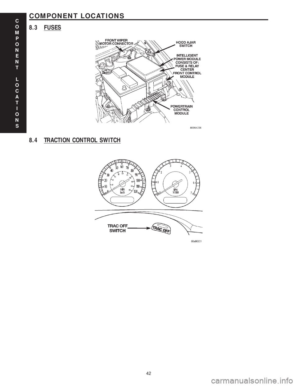
8.3 FUSES
8.4 TRACTION CONTROL SWITCH
C
O
M
P
O
N
E
N
T
L
O
C
A
T
I
O
N
S
42
COMPONENT LOCATIONS