2001 AUDI A4 door lock
[x] Cancel search: door lockPage 11 of 88
Downloaded from www.Manualslib.com manuals search engine
11
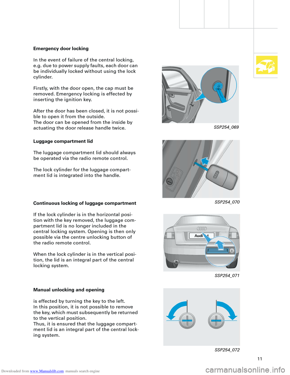
Luggage compartment lid
The luggage compartment lid should always
be operated via the radio remote control.
The lock cylinder for the luggage compart-
ment lid is integrated into the handle.
Emergency door locking
In the event of failure of the central locking,
e.g. due to power supply faults, each door can
be individually locked without using the lock
cylinder.
Firstly, with the door open, the cap must be
removed. Emergency locking is effected by
inserting the ignition key.
After the door has been closed, it is not possi-
ble to open it from the outside.
The door can be opened from the inside by
actuating the door release handle twice.
Continuous locking of luggage compartment
If the lock cylinder is in the horizontal posi-
tion with the key removed, the luggage com-
partment lid is no longer included in the
central locking system. Opening is then only
possible via the centre unlocking button of
the radio remote control.
When the lock cylinder is in the vertical posi-
tion, the lid is an integral part of the central
locking system.
Manual unlocking and opening
is effected by turning the key to the left.
In this position, it is not possible to remove
the key, which must subsequently be returned
to the vertical position.
Thus, it is ensured that the luggage compart-
ment lid is an integral part of the central lock-
ing system.
SSP254_069
SSP254_070
SSP254_071
SSP254_072
Page 17 of 88
Downloaded from www.Manualslib.com manuals search engine
17
Crash signal processing
There are two separate crash signal outputs:
One crash signal is output via the conven-
tional wiring and triggers the following func-
tions:
– Transmitting an emergency call via the
control unit for telephone/telematics J526
(optional)
– unlocking the vehicle,
– Switch on interior light
(switch must be set to door contact),
– switching on hazard warning lights via the
central convenience electronics J393.
The auxiliary heater J162 (optional) is
switched off by the central convenience
electronics J393 via a CAN convenience
message.
The second crash signal output functions via
the convenience CAN bus, which switches off
the engine fuel supply via the engine control
unit J220.
Page 57 of 88
Downloaded from www.Manualslib.com manuals search engine
57
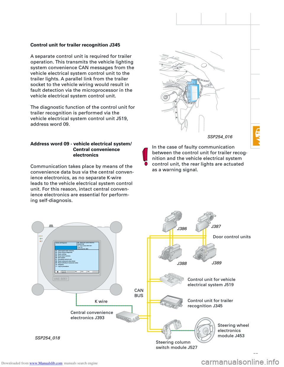
Control unit for trailer recognition J345
A separate control unit is required for trailer
operation. This transmits the vehicle lighting
system convenience CAN messages from the
vehicle electrical system control unit to the
trailer lights. A parallel link from the trailer
socket to the vehicle wiring would result in
fault detection via the microprocessor in the
vehicle electrical system control unit.
The diagnostic function of the control unit for
trailer recognition is performed via the
vehicle electrical system control unit J519,
address word 09.
In the case of faulty communication
between the control unit for trailer recog-
nition and the vehicle electrical system
control unit, the rear lights are actuated
as a warning signal.
RT
Address word 09 - vehicle electrical system/
Central convenience
electronics
Communication takes place by means of the
convenience data bus via the central conven-
ience electronics, as no separate K-wire
leads to the vehicle electrical system control
unit. For this reason, intact central conven-
ience electronics are essential for perform-
ing self-diagnosis.
K wireCAN
BUS
Central convenience
electronics J393
SSP254_018J389
J388J387
J386
Door control units
Control unit for vehicle
electrical system J519
Control unit for trailer
recognition J345
09 – Electronic central electrics
8E0907279B
int. load module RDW 0811
Code 101
Dealership No. 6803
02 - Interrogate fault memory
03 - Final control diagnosis
04 - Basic setting
05 - Erase fault memory
06 - End output
07 - Encoding control unit
08 - Read measured value block
09 - Read individual measured value
10 - Adaption
11 - Log-in procedure
Measuring
equipmentSkip PrintHelp
Steering column
switch module J527
Vehicle self-diagnosis
Steering wheel
electronics
module J453
SSP254_016
VAS 5051
Page 58 of 88
Downloaded from www.Manualslib.com manuals search engine
58
In the basic version without rear electric win-
dow lifters, central locking control of the rear
doors is assumed by the central convenience
electronics.
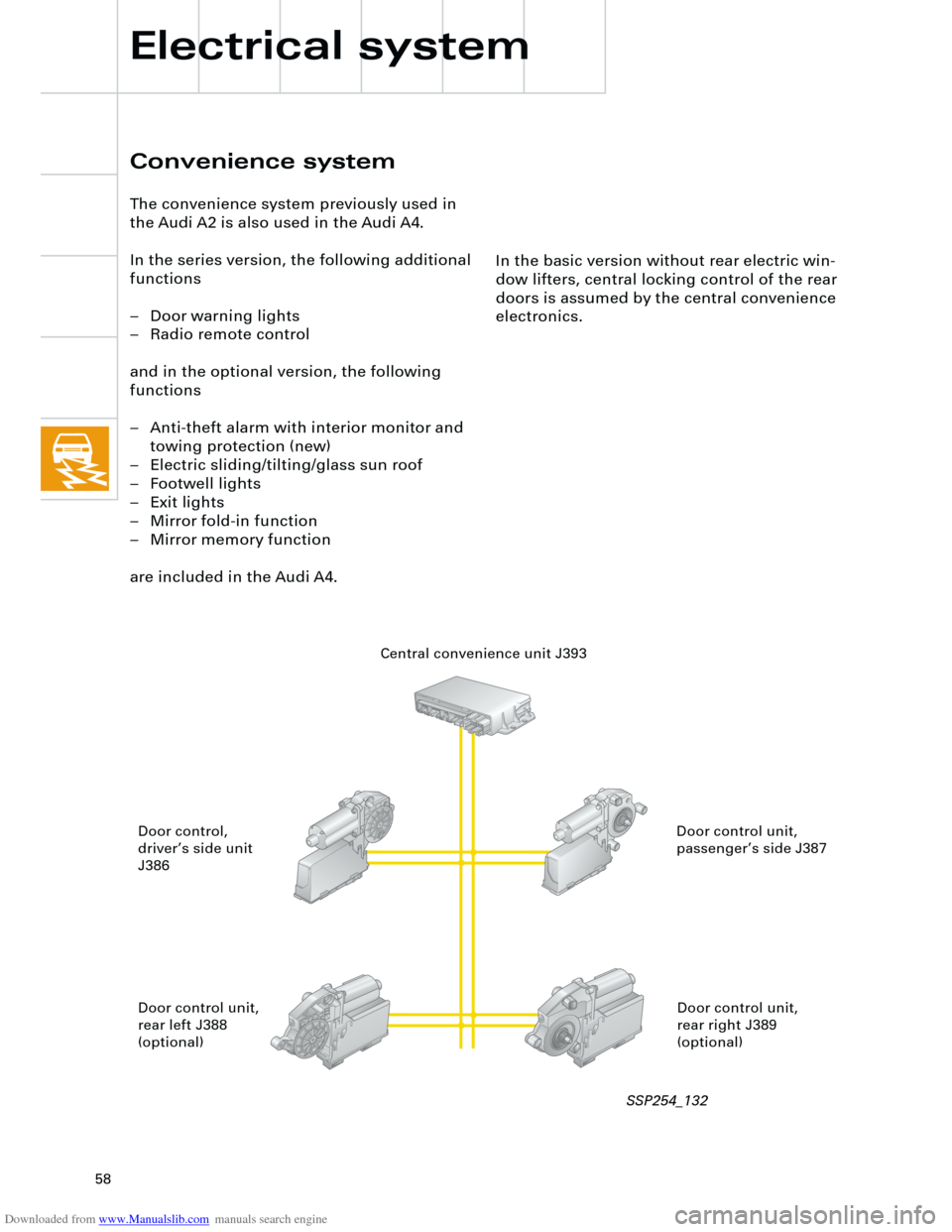
Convenience system
The convenience system previously used in
the Audi A2 is also used in the Audi A4.
In the series version, the following additional
functions
– Door warning lights
– Radio remote control
and in the optional version, the following
functions
– Anti-theft alarm with interior monitor and
towing protection (new)
– Electric sliding/tilting/glass sun roof
– Footwell lights
– Exit lights
– Mirror fold-in function
– Mirror memory function
are included in the Audi A4.
Electrical system
Central convenience unit J393
Door control unit,
passenger’s side J387 Door control,
driver’s side unit
J386
Door control unit,
rear right J389
(optional) Door control unit,
rear left J388
(optional)
SSP254_132
Page 59 of 88
Downloaded from www.Manualslib.com manuals search engine
59
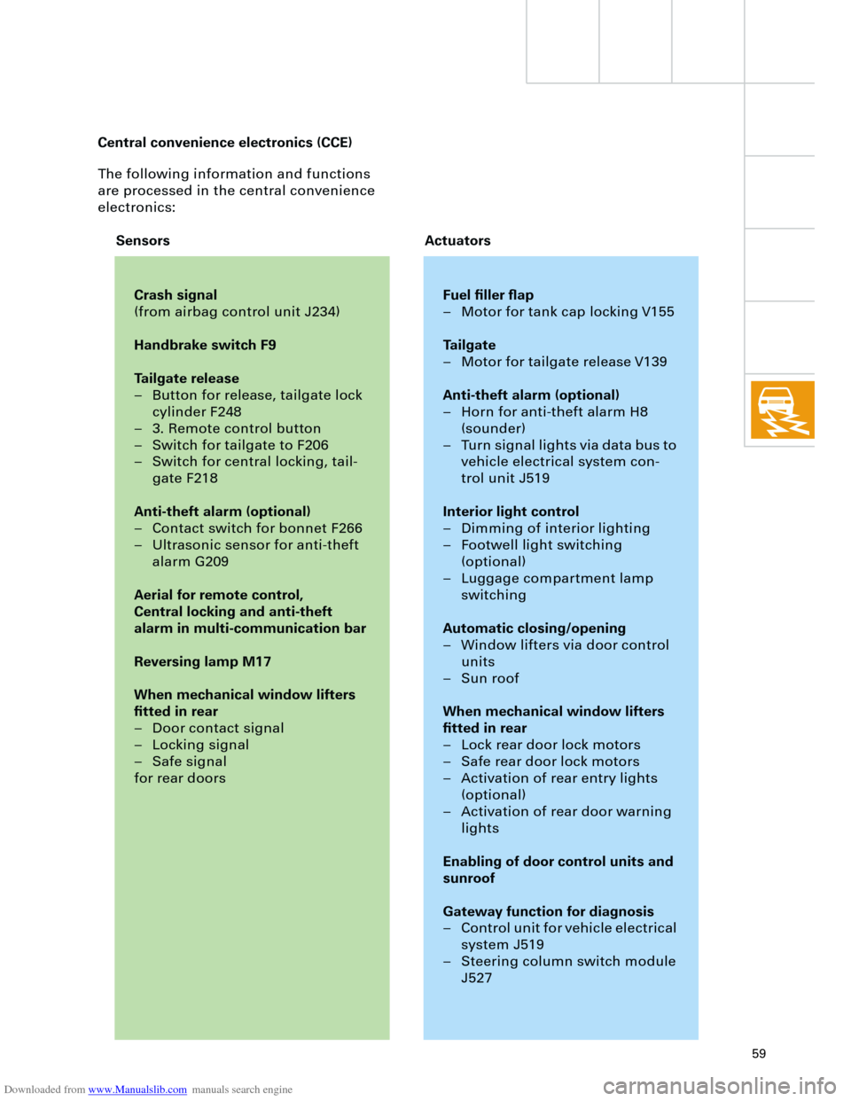
The following information and functions
are processed in the central convenience
electronics:
Crash signal
(from airbag control unit J234)
Handbrake switch F9
Tailgate release
– Button for release, tailgate lock
cylinder F248
– 3. Remote control button
– Switch for tailgate to F206
– Switch for central locking, tail-
gate F218
Anti-theft alarm (optional)
– Contact switch for bonnet F266
– Ultrasonic sensor for anti-theft
alarm G209
Aerial for remote control,
Central locking and anti-theft
alarm in multi-communication bar
Reversing lamp M17
When mechanical window lifters
fitted in rear
– Door contact signal
– Locking signal
– Safe signal
for rear doors
Fuel filler flap
– Motor for tank cap locking V155
Tailgate
– Motor for tailgate release V139
Anti-theft alarm (optional)
– Horn for anti-theft alarm H8
(sounder)
– Turn signal lights via data bus to
vehicle electrical system con-
trol unit J519
Interior light control
– Dimming of interior lighting
– Footwell light switching
(optional)
– Luggage compartment lamp
switching
Automatic closing/opening
– Window lifters via door control
units
– Sun roof
When mechanical window lifters
fitted in rear
– Lock rear door lock motors
– Safe rear door lock motors
– Activation of rear entry lights
(optional)
– Activation of rear door warning
lights
Enabling of door control units and
sunroof
Gateway function for diagnosis
– Control unit for vehicle electrical
system J519
– Steering column switch module
J527
Sensors Actuators Central convenience electronics (CCE)
Page 60 of 88
Downloaded from www.Manualslib.com manuals search engine
60
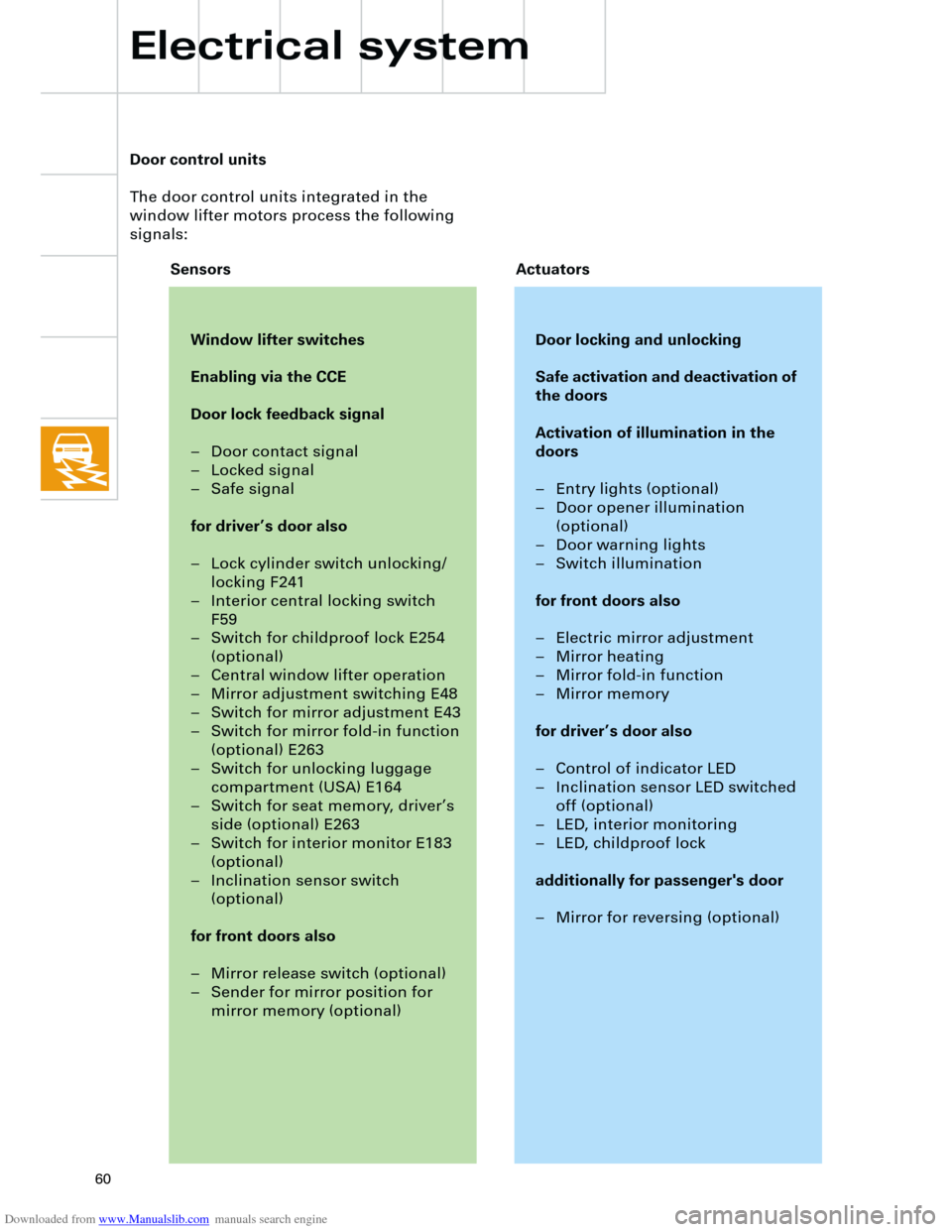
Door control units
The door control units integrated in the
window lifter motors process the following
signals:
Window lifter switches
Enabling via the CCE
Door lock feedback signal
– Door contact signal
– Locked signal
– Safe signal
for driver’s door also
– Lock cylinder switch unlocking/
locking F241
– Interior central locking switch
F59
– Switch for childproof lock E254
(optional)
– Central window lifter operation
– Mirror adjustment switching E48
– Switch for mirror adjustment E43
– Switch for mirror fold-in function
(optional) E263
– Switch for unlocking luggage
compartment (USA) E164
– Switch for seat memory, driver’s
side (optional) E263
– Switch for interior monitor E183
(optional)
– Inclination sensor switch
(optional)
for front doors also
– Mirror release switch (optional)
– Sender for mirror position for
mirror memory (optional)
Door locking and unlocking
Safe activation and deactivation of
the doors
Activation of illumination in the
doors
– Entry lights (optional)
– Door opener illumination
(optional)
– Door warning lights
– Switch illumination
for front doors also
– Electric mirror adjustment
– Mirror heating
– Mirror fold-in function
– Mirror memory
for driver’s door also
– Control of indicator LED
– Inclination sensor LED switched
off (optional)
– LED, interior monitoring
– LED, childproof lock
additionally for passenger's door
– Mirror for reversing (optional)
Sensors Actuators
Electrical system
Page 62 of 88
Downloaded from www.Manualslib.com manuals search engine
62
TS
Electrical system
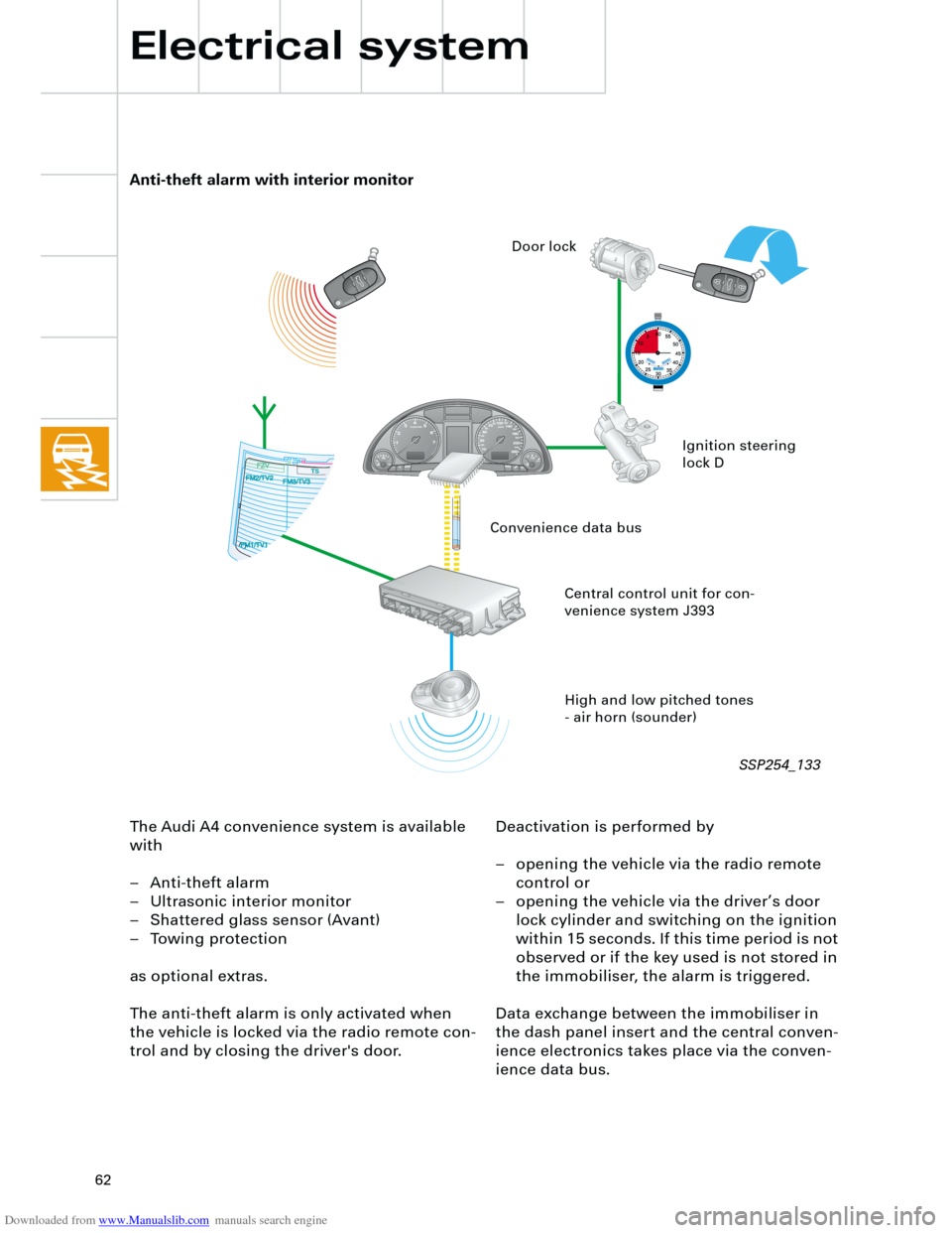
The Audi A4 convenience system is available
with
– Anti-theft alarm
– Ultrasonic interior monitor
– Shattered glass sensor (Avant)
– Towing protection
as optional extras.
The anti-theft alarm is only activated when
the vehicle is locked via the radio remote con-
trol and by closing the driver's door.Deactivation is performed by
– opening the vehicle via the radio remote
control or
– opening the vehicle via the driver’s door
lock cylinder and switching on the ignition
within 15 seconds. If this time period is not
observed or if the key used is not stored in
the immobiliser, the alarm is triggered.
Data exchange between the immobiliser in
the dash panel insert and the central conven-
ience electronics takes place via the conven-
ience data bus.
Anti-theft alarm with interior monitor
High and low pitched tones
- air horn (sounder) Central control unit for con-
venience system J393Ignition steering
lock D Door lock
Convenience data bus
SSP254_133