Page 15 of 88

Downloaded from www.Manualslib.com manuals search engine
15
Re-encoding of the airbag control unit is no
longer possible after the first crash data mes-
sage is stored.
Triggering is performed in two thresholds
depending upon the deceleration value:
– Threshold 1 = belt tensioners only
– Threshold 2 = belt tensioners and airbag(s)
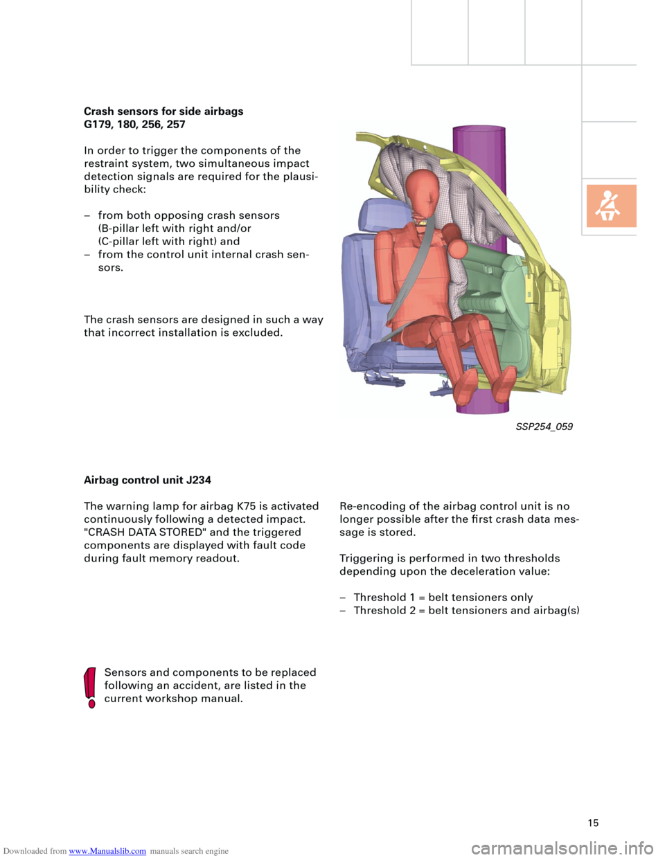
Crash sensors for side airbags
G179, 180, 256, 257
In order to trigger the components of the
restraint system, two simultaneous impact
detection signals are required for the plausi-
bility check:
– from both opposing crash sensors
(B-pillar left with right and/or
(C-pillar left with right) and
– from the control unit internal crash sen-
sors.
The crash sensors are designed in such a way
that incorrect installation is excluded.
Airbag control unit J234
The warning lamp for airbag K75 is activated
continuously following a detected impact.
"CRASH DATA STORED" and the triggered
components are displayed with fault code
during fault memory readout.
Sensors and components to be replaced
following an accident, are listed in the
current workshop manual.
SSP254_059
Page 40 of 88
Downloaded from www.Manualslib.com manuals search engine
40
Electrical system
Setting buttons for digital clock,
date and instrument illuminationAuto-check system
Call-up button for
service interval
indicatorReset button for trip
recorder
Dash panel insert
There are two dash panel insert versions:
– "lowline"
– "highline"
The "highline" version is equipped with a
high-quality colour display for the driver infor-
mation system and is installed in vehicles
with navigation systems as well as telematics.The dash panel insert of the new Audi A4 is
equipped with
– the gateway for linking the three data bus
systems: drive, convenience, information
– and the immobiliser III.
Cruise control system ON
SSP254_012
Page 41 of 88
Downloaded from www.Manualslib.com manuals search engine
41
In order to ensure good signal reception for
the radio clock, the receiver is installed in the
rear bumper bar. User prompt in the centre display via the con-
trol switch in the centre console, is only avail-
able in vehicles with
– navigation system ("highline" version only)
and/or
– telematics and/or
– auxiliary heater and/or
– tyre pressure monitoring.
The optional driver information system
includes the following functions:
– radio clock
– auto-check system
– on-board computer.
The km range is indicated in the basic ver-
sion.
Ear
th
Radio signal
+ 5
V
SSP254_104
SSP254_108
Page 42 of 88
Downloaded from www.Manualslib.com manuals search engine
42
The Audi A4 quattro is equipped with two fuel
gauge senders G and G169.
Sender G registers the lower, and sender
G169 the upper partial volume in the fuel
tank.
The signals from senders G and G169 are
evaluated separately. The calculated litre
values are then added and displayed. A new feature of the Auto-Check system
is the position-dependent bulb monitor display.
The fault message is transmitted from the vehi-
cle electrical system control unit J519, via the
convenience data bus, to the dash panel insert
J285 and appears on the centre display.
Electrical system
Fuel gauge
sender 2, G169 Fuel gauge
sender G
SSP254_123
Control unit with
display unit in dash
panel processor J285
Control unit for vehicle
electrical system J519 Convenience data
bus
SSP254_118
SSP254_125
Page 43 of 88

Downloaded from www.Manualslib.com manuals search engine
43
A further innovation is the display of the max-
imum and minimum engine oil levels in the
measured value block after the most recent
service operation.
The adaptation of the mileage/kilometre read-
ing after replacement of the dash panel
insert, is possible (several attempts) up to a
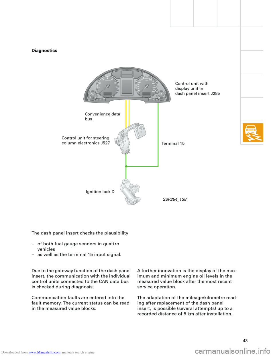
recorded distance of 5 km after installation. The dash panel insert checks the plausibility
– of both fuel gauge senders in quattro
vehicles
– as well as the terminal 15 input signal.
Due to the gateway function of the dash panel
insert, the communication with the individual
control units connected to the CAN data bus
is checked during diagnosis.
Communication faults are entered into the
fault memory. The current status can be read
in the measured value blocks.
Control unit with
display unit in
dash panel insert J285
Control unit for steering
column electronics J527
Ignition lock D Convenience data
bus
Terminal 15
Diagnostics
SSP254_138
Page 56 of 88

Downloaded from www.Manualslib.com manuals search engine
56
Electrical system
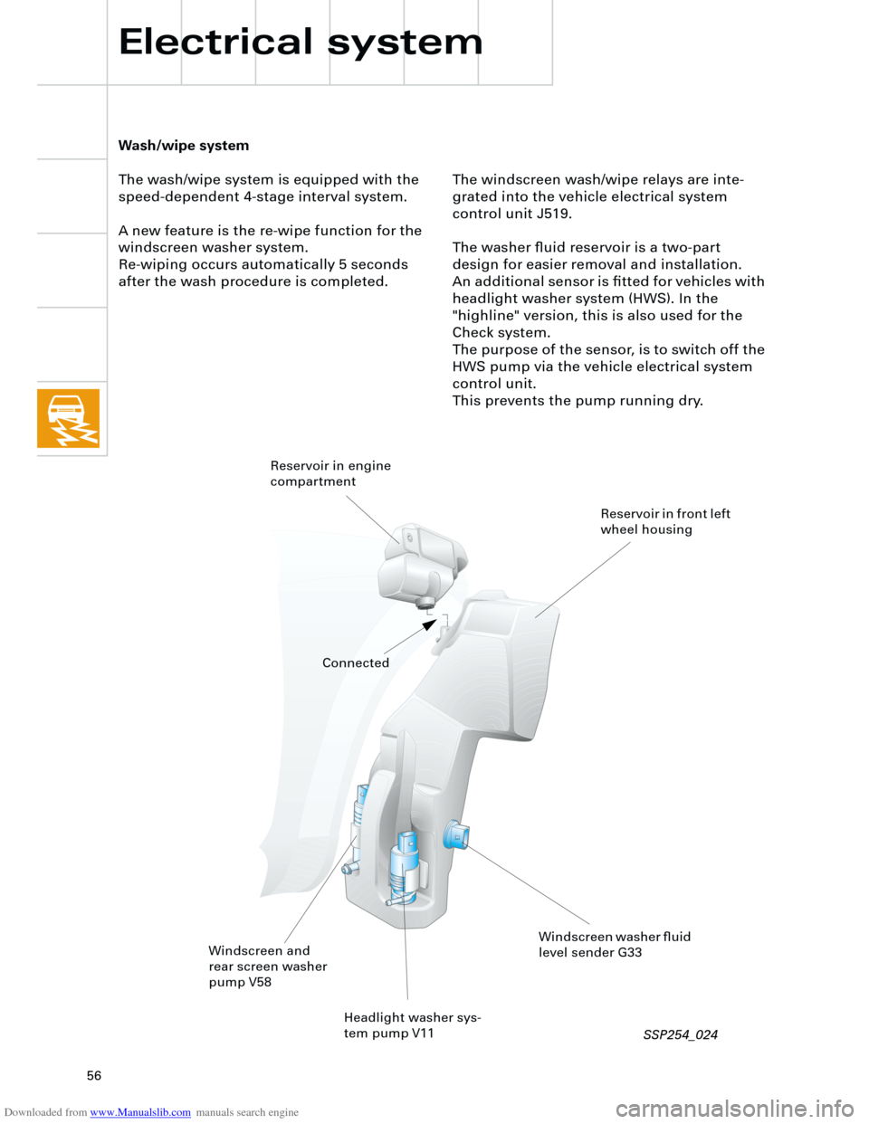
The windscreen wash/wipe relays are inte-
grated into the vehicle electrical system
control unit J519.
The washer fluid reservoir is a two-part
design for easier removal and installation.
An additional sensor is fitted for vehicles with
headlight washer system (HWS). In the
"highline" version, this is also used for the
Check system.
The purpose of the sensor, is to switch off the
HWS pump via the vehicle electrical system
control unit.
This prevents the pump running dry.
Wash/wipe system
The wash/wipe system is equipped with the
speed-dependent 4-stage interval system.
A new feature is the re-wipe function for the
windscreen washer system.
Re-wiping occurs automatically 5 seconds
after the wash procedure is completed.
Headlight washer sys-
tem pump V11
Windscreen and
rear screen washer
pump V58
Windscreen washer fluid
level sender G33 Reservoir in engine
compartment
Reservoir in front left
wheel housing
Connected
SSP254_024
Page 68 of 88

Downloaded from www.Manualslib.com manuals search engine
68
Example:
If the radio is switched on with the ignition
key (S-contact) this requires the exchange of
data between three control units:
– Steering column electronics,
– dash panel insert (gateway) and
– radio.
If the radio does not switch on,
– the signal input in the steering column
electronics (terminal 86S),
– communication between the steering col-
umn electronics and the dash panel
(convenience data bus) and
– communication between the dash panel
and the radio
(data bus information system)
must be checked.
Diagnostics
For diagnosis of radio systems concert II and
symphony II, current consumption of aerial
diversity is monitored via the intermittent
frequency (IF) wiring.
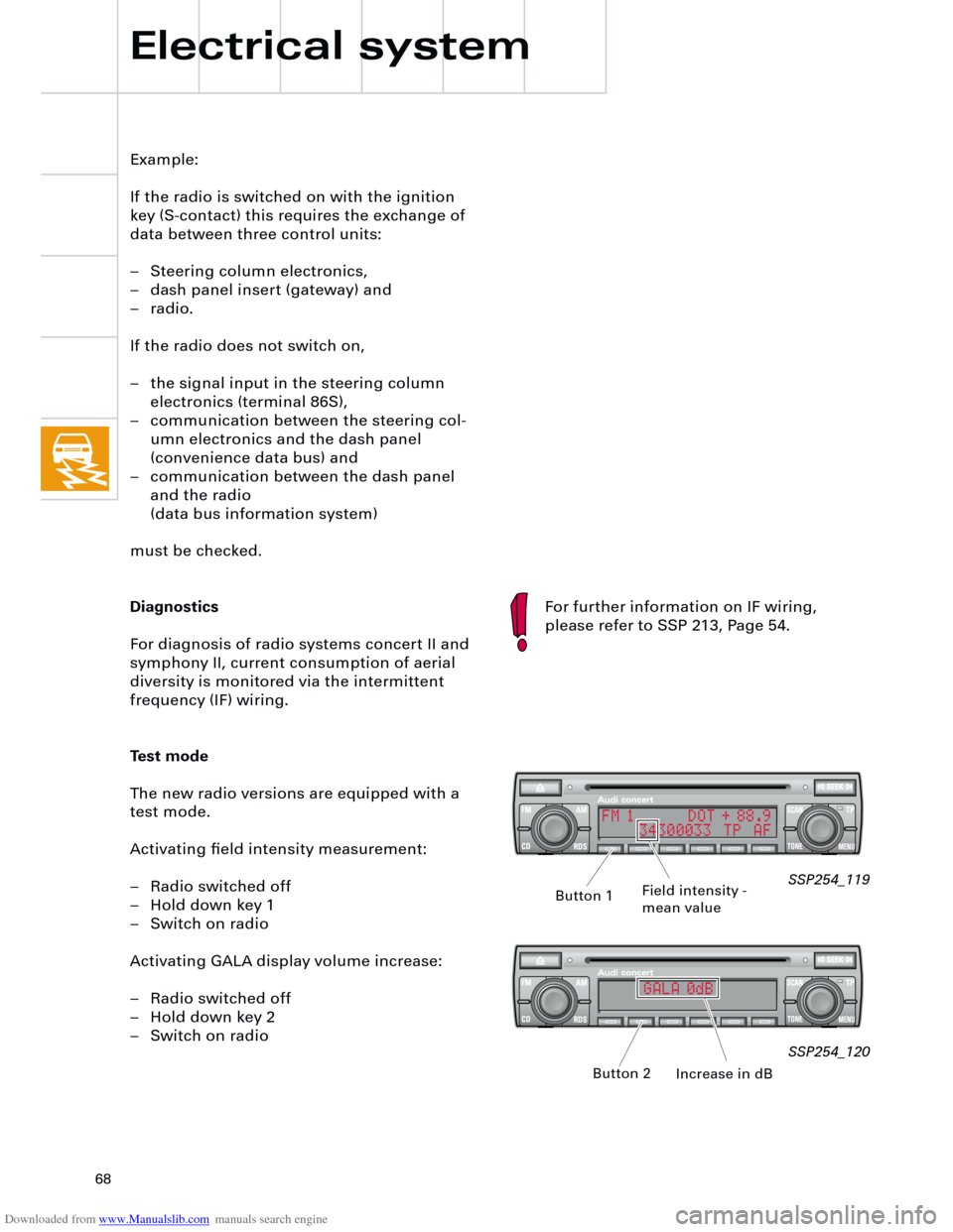
Test mode
The new radio versions are equipped with a
test mode.
Activating field intensity measurement:
– Radio switched off
– Hold down key 1
– Switch on radio
Activating GALA display volume increase:
– Radio switched off
– Hold down key 2
– Switch on radio
Electrical system
SSP254_119
SSP254_120
Field intensity -
mean value
Increase in dB Button 1
Button 2
For further information on IF wiring,
please refer to SSP 213, Page 54.
FM 1 DOT + 88.9
34300033 TP AF
GALA 0dB