2001 AUDI A4 phone
[x] Cancel search: phonePage 5 of 88
Downloaded from www.Manualslib.com manuals search engine
5
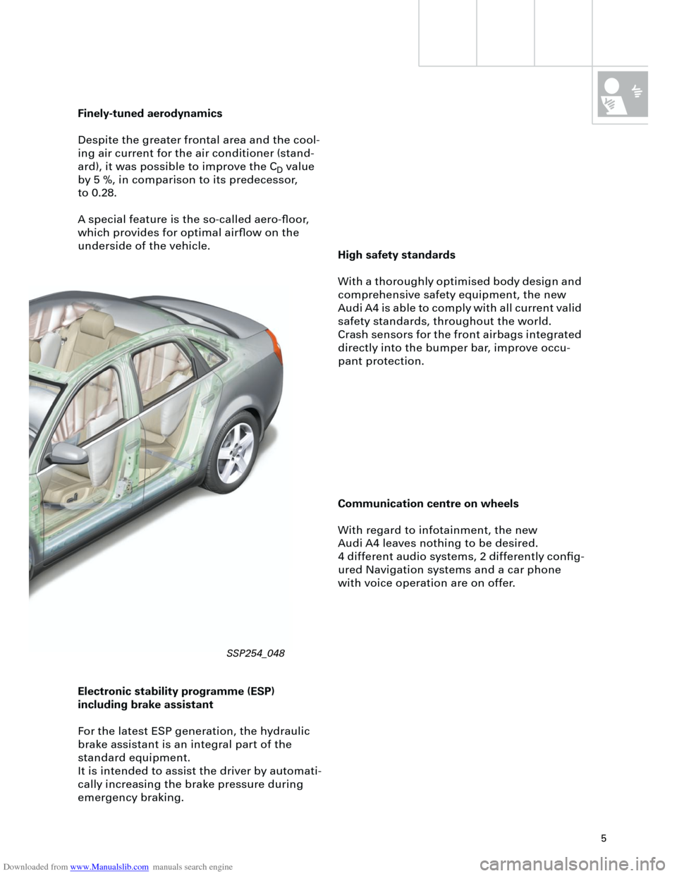
High safety standards
With a thoroughly optimised body design and
comprehensive safety equipment, the new
Audi A4 is able to comply with all current valid
safety standards, throughout the world.
Crash sensors for the front airbags integrated
directly into the bumper bar, improve occu-
pant protection.
Finely-tuned aerodynamics
Despite the greater frontal area and the cool-
ing air current for the air conditioner (stand-
ard), it was possible to improve the C
D
value
by 5 %, in comparison to its predecessor,
to 0.28.
A special feature is the so-called aero-floor,
which provides for optimal airflow on the
underside of the vehicle.
Communication centre on wheels
With regard to infotainment, the new
Audi A4 leaves nothing to be desired.
4 different audio systems, 2 differently config-
ured Navigation systems and a car phone
with voice operation are on offer.
Electronic stability programme (ESP)
including brake assistant
For the latest ESP generation, the hydraulic
brake assistant is an integral part of the
standard equipment.
It is intended to assist the driver by automati-
cally increasing the brake pressure during
emergency braking.
SSP254_048
Page 13 of 88
Downloaded from www.Manualslib.com manuals search engine
13
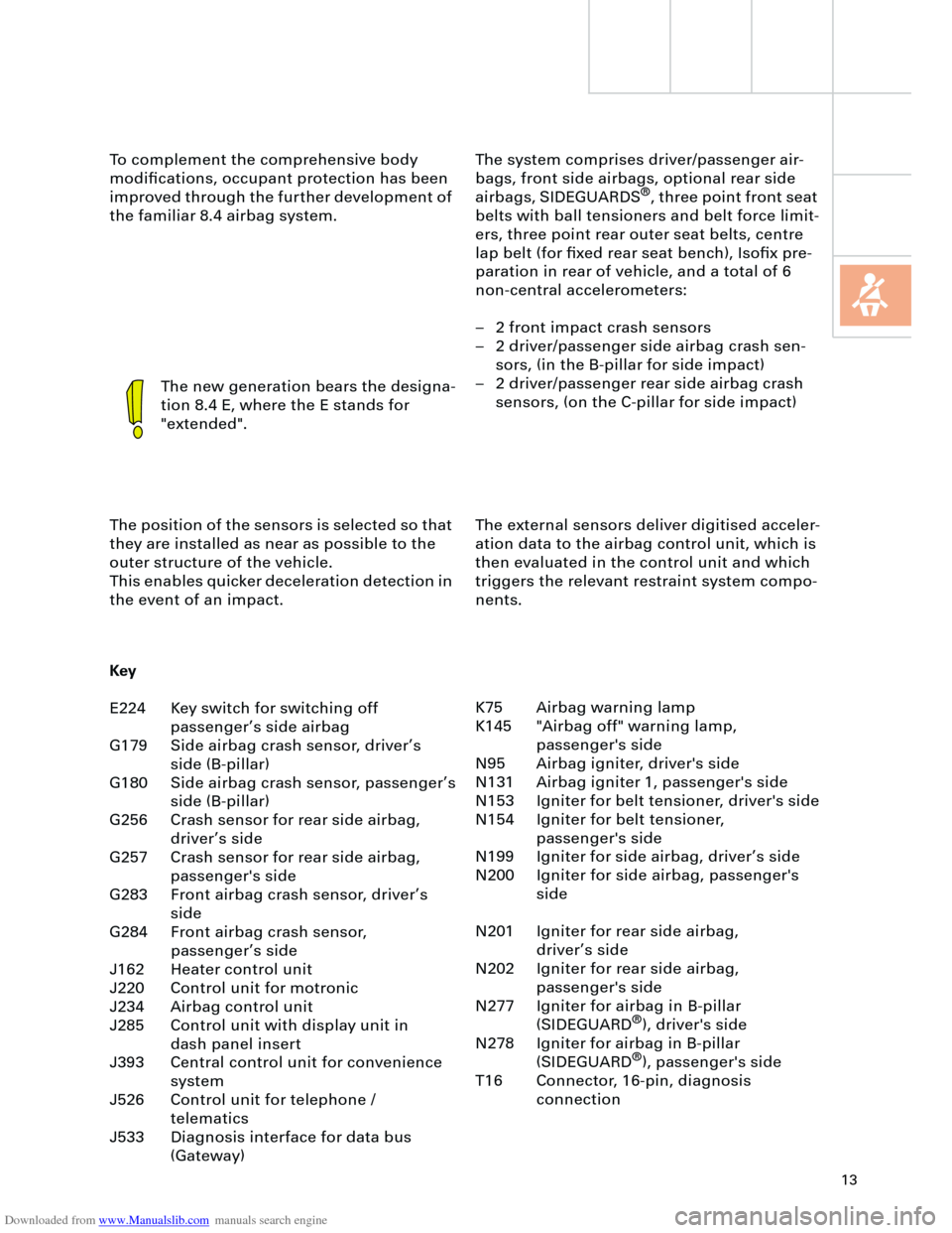
The system comprises driver/passenger air-
bags, front side airbags, optional rear side
airbags, SIDEGUARDS
®
, three point front seat
belts with ball tensioners and belt force limit-
ers, three point rear outer seat belts, centre
lap belt (for fixed rear seat bench), Isofix pre-
paration in rear of vehicle, and a total of 6
non-central accelerometers:
– 2 front impact crash sensors
– 2 driver/passenger side airbag crash sen-
sors, (in the B-pillar for side impact)
– 2 driver/passenger rear side airbag crash
sensors, (on the C-pillar for side impact) To complement the comprehensive body
modifications, occupant protection has been
improved through the further development of
the familiar 8.4 airbag system.
The new generation bears the designa-
tion 8.4 E, where the E stands for
"extended".
The position of the sensors is selected so that
they are installed as near as possible to the
outer structure of the vehicle.
This enables quicker deceleration detection in
the event of an impact.The external sensors deliver digitised acceler-
ation data to the airbag control unit, which is
then evaluated in the control unit and which
triggers the relevant restraint system compo-
nents.
Key
E224 Key switch for switching off
passenger’s side airbag
G179 Side airbag crash sensor, driver’s
side (B-pillar)
G180 Side airbag crash sensor, passenger’s
side (B-pillar)
G256 Crash sensor for rear side airbag,
driver’s side
G257 Crash sensor for rear side airbag,
passenger's side
G283 Front airbag crash sensor, driver’s
side
G284 Front airbag crash sensor,
passenger’s side
J162 Heater control unit
J220 Control unit for motronic
J234 Airbag control unit
J285 Control unit with display unit in
dash panel insert
J393 Central control unit for convenience
system
J526 Control unit for telephone /
telematics
J533 Diagnosis interface for data bus
(Gateway)K75 Airbag warning lamp
K145 "Airbag off" warning lamp,
passenger's side
N95 Airbag igniter, driver's side
N131 Airbag igniter 1, passenger's side
N153 Igniter for belt tensioner, driver's side
N154 Igniter for belt tensioner,
passenger's side
N199 Igniter for side airbag, driver’s side
N200 Igniter for side airbag, passenger's
side
N201 Igniter for rear side airbag,
driver’s side
N202 Igniter for rear side airbag,
passenger's side
N277 Igniter for airbag in B-pillar
(SIDEGUARD
®
), driver's side
N278 Igniter for airbag in B-pillar
(SIDEGUARD
®
), passenger's side
T16 Connector, 16-pin, diagnosis
connection
Page 17 of 88
Downloaded from www.Manualslib.com manuals search engine
17
Crash signal processing
There are two separate crash signal outputs:
One crash signal is output via the conven-
tional wiring and triggers the following func-
tions:
– Transmitting an emergency call via the
control unit for telephone/telematics J526
(optional)
– unlocking the vehicle,
– Switch on interior light
(switch must be set to door contact),
– switching on hazard warning lights via the
central convenience electronics J393.
The auxiliary heater J162 (optional) is
switched off by the central convenience
electronics J393 via a CAN convenience
message.
The second crash signal output functions via
the convenience CAN bus, which switches off
the engine fuel supply via the engine control
unit J220.
Page 36 of 88
Downloaded from www.Manualslib.com manuals search engine
36
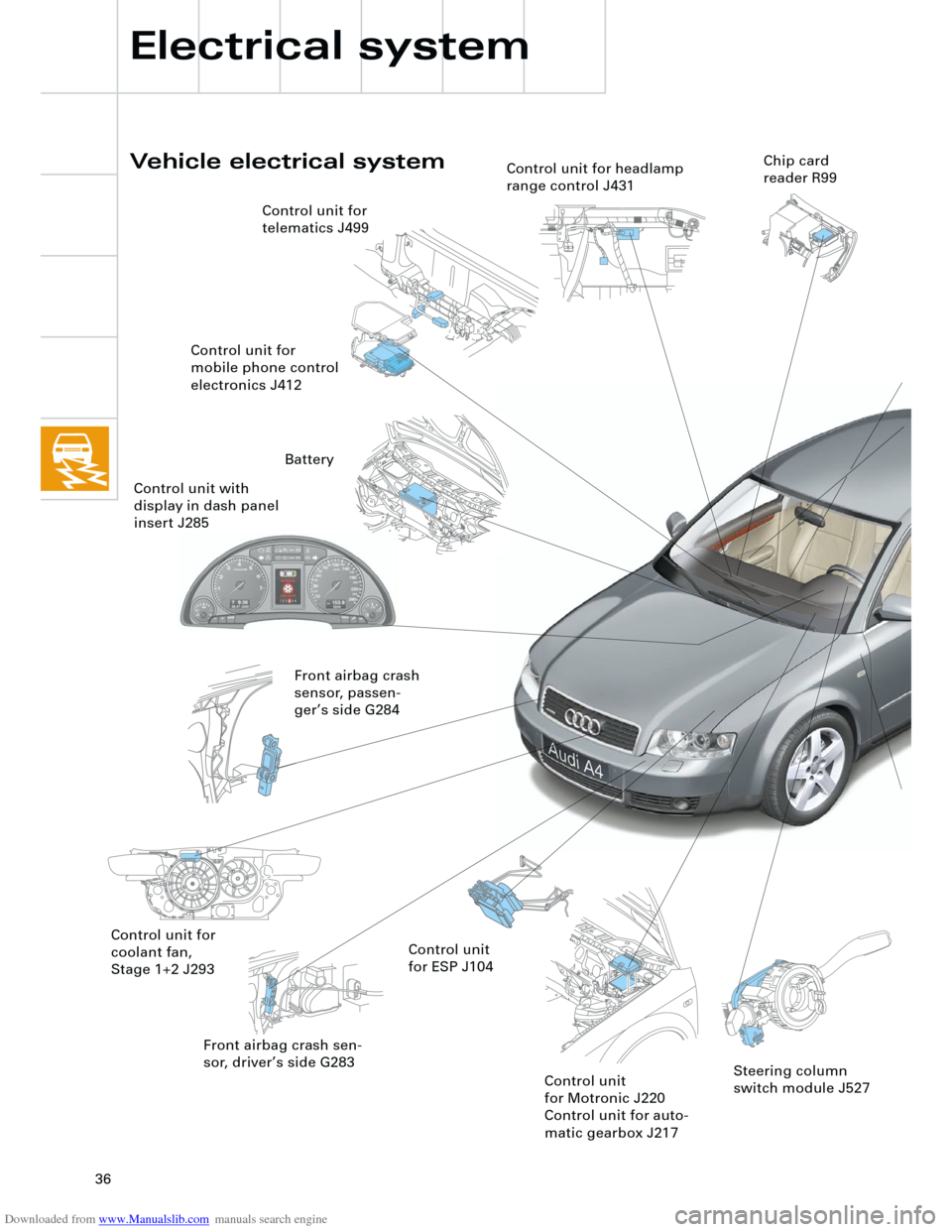
Front airbag crash sen-
sor, driver’s side G283
Vehicle electrical system
Electrical system
Control unit for
coolant fan,
Stage 1+2 J293Control unit
for ESP J104 Control unit for
telematics J499
Control unit for
mobile phone control
electronics J412
Front airbag crash
sensor, passen-
ger’s side G284
Control unit
for Motronic J220
Control unit for auto-
matic gearbox J217
Control unit for headlamp
range control J431Chip card
reader R99
Steering column
switch module J527
Battery
Control unit with
display in dash panel
insert J285
Page 39 of 88
Downloaded from www.Manualslib.com manuals search engine
39
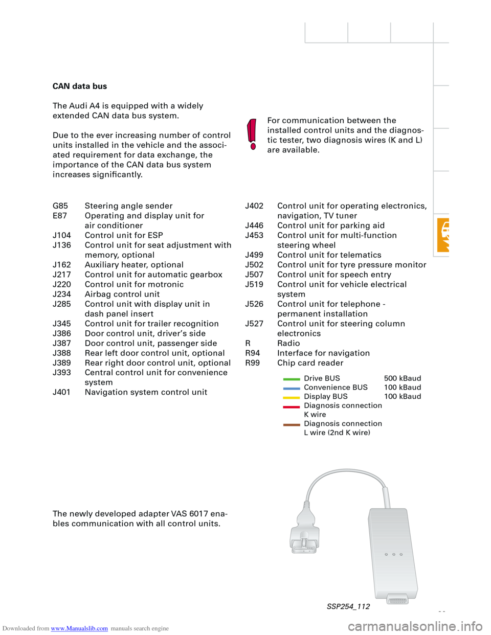
CAN data bus
The Audi A4 is equipped with a widely
extended CAN data bus system.
Due to the ever increasing number of control
units installed in the vehicle and the associ-
ated requirement for data exchange, the
importance of the CAN data bus system
increases significantly.For communication between the
installed control units and the diagnos-
tic tester, two diagnosis wires (K and L)
are available.
The newly developed adapter VAS 6017 ena-
bles communication with all control units.
Drive BUS 500 kBaud
Convenience BUS 100 kBaud
Display BUS 100 kBaud
Diagnosis connection
K wire
Diagnosis connection
L wire (2nd K wire)
J402 Control unit for operating electronics,
navigation, TV tuner
J446 Control unit for parking aid
J453 Control unit for multi-function
steering wheel
J499 Control unit for telematics
J502 Control unit for tyre pressure monitor
J507 Control unit for speech entry
J519 Control unit for vehicle electrical
system
J526 Control unit for telephone -
permanent installation
J527 Control unit for steering column
electronics
R Radio
R94 Interface for navigation
R99 Chip card reader G85 Steering angle sender
E87 Operating and display unit for
air conditioner
J104 Control unit for ESP
J136 Control unit for seat adjustment with
memory, optional
J162 Auxiliary heater, optional
J217 Control unit for automatic gearbox
J220 Control unit for motronic
J234 Airbag control unit
J285 Control unit with display unit in
dash panel insert
J345 Control unit for trailer recognition
J386 Door control unit, driver’s side
J387 Door control unit, passenger side
J388 Rear left door control unit, optional
J389 Rear right door control unit, optional
J393 Central control unit for convenience
system
J401 Navigation system control unit
SSP254_112
Page 69 of 88
Downloaded from www.Manualslib.com manuals search engine
69
Navigation IV and Navigation Plus-D
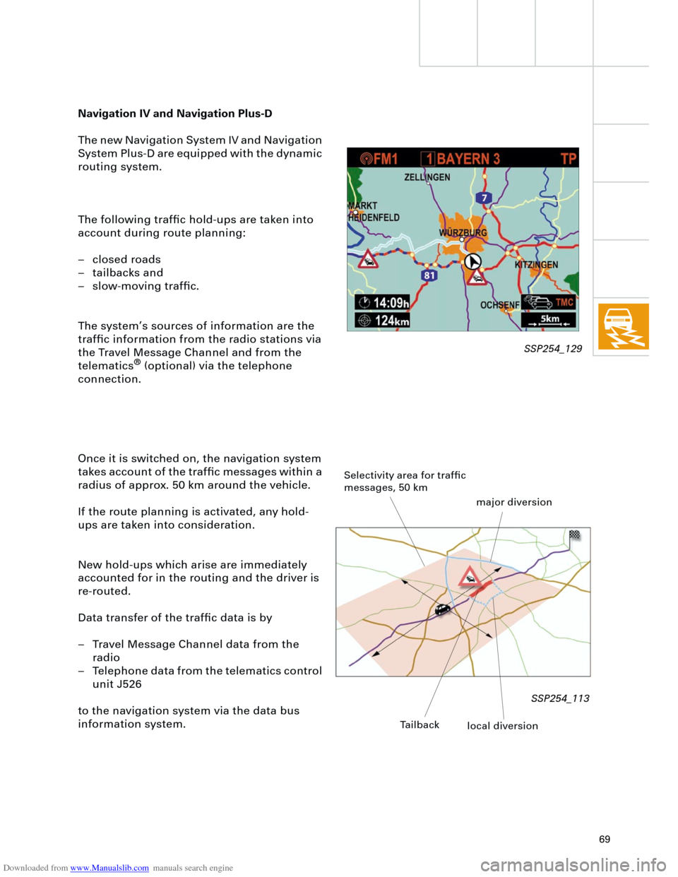
The new Navigation System IV and Navigation
System Plus-D are equipped with the dynamic
routing system.
The following traffic hold-ups are taken into
account during route planning:
– closed roads
– tailbacks and
– slow-moving traffic.
The system’s sources of information are the
traffic information from the radio stations via
the Travel Message Channel and from the
telematics
®
(optional) via the telephone
connection.
Once it is switched on, the navigation system
takes account of the traffic messages within a
radius of approx. 50 km around the vehicle.
If the route planning is activated, any hold-
ups are taken into consideration.
New hold-ups which arise are immediately
accounted for in the routing and the driver is
re-routed.
Data transfer of the traffic data is by
– Travel Message Channel data from the
radio
– Telephone data from the telematics control
unit J526
to the navigation system via the data bus
information system.
Selectivity area for traffic
messages, 50 km
major diversion
Tailback
local diversion
SSP254_129
SSP254_113
Page 70 of 88
Downloaded from www.Manualslib.com manuals search engine
70
TELE
RETURN
INFO
NAV
Menu
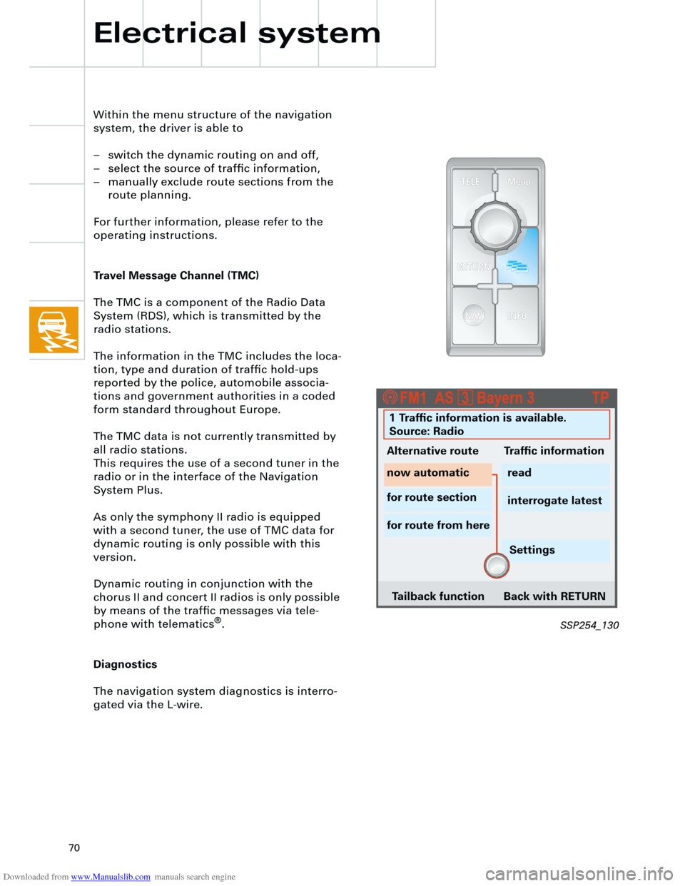
Within the menu structure of the navigation
system, the driver is able to
– switch the dynamic routing on and off,
– select the source of traffic information,
– manually exclude route sections from the
route planning.
For further information, please refer to the
operating instructions.
Travel Message Channel (TMC)
The TMC is a component of the Radio Data
System (RDS), which is transmitted by the
radio stations.
The information in the TMC includes the loca-
tion, type and duration of traffic hold-ups
reported by the police, automobile associa-
tions and government authorities in a coded
form standard throughout Europe.
The TMC data is not currently transmitted by
all radio stations.
This requires the use of a second tuner in the
radio or in the interface of the Navigation
System Plus.
As only the symphony II radio is equipped
with a second tuner, the use of TMC data for
dynamic routing is only possible with this
version.
Dynamic routing in conjunction with the
chorus II and concert II radios is only possible
by means of the traffic messages via tele-
phone with telematics
®
.
Diagnostics
The navigation system diagnostics is interro-
gated via the L-wire.
Electrical system
SSP254_130
1 Traffic information is available.
Source: Radio
Alternative route Traffic information
now automatic
for route section
for route from hereread
interrogate latest
Settings
Tailback function Back with RETURN
Page 72 of 88
Downloaded from www.Manualslib.com manuals search engine
72
TS
TS
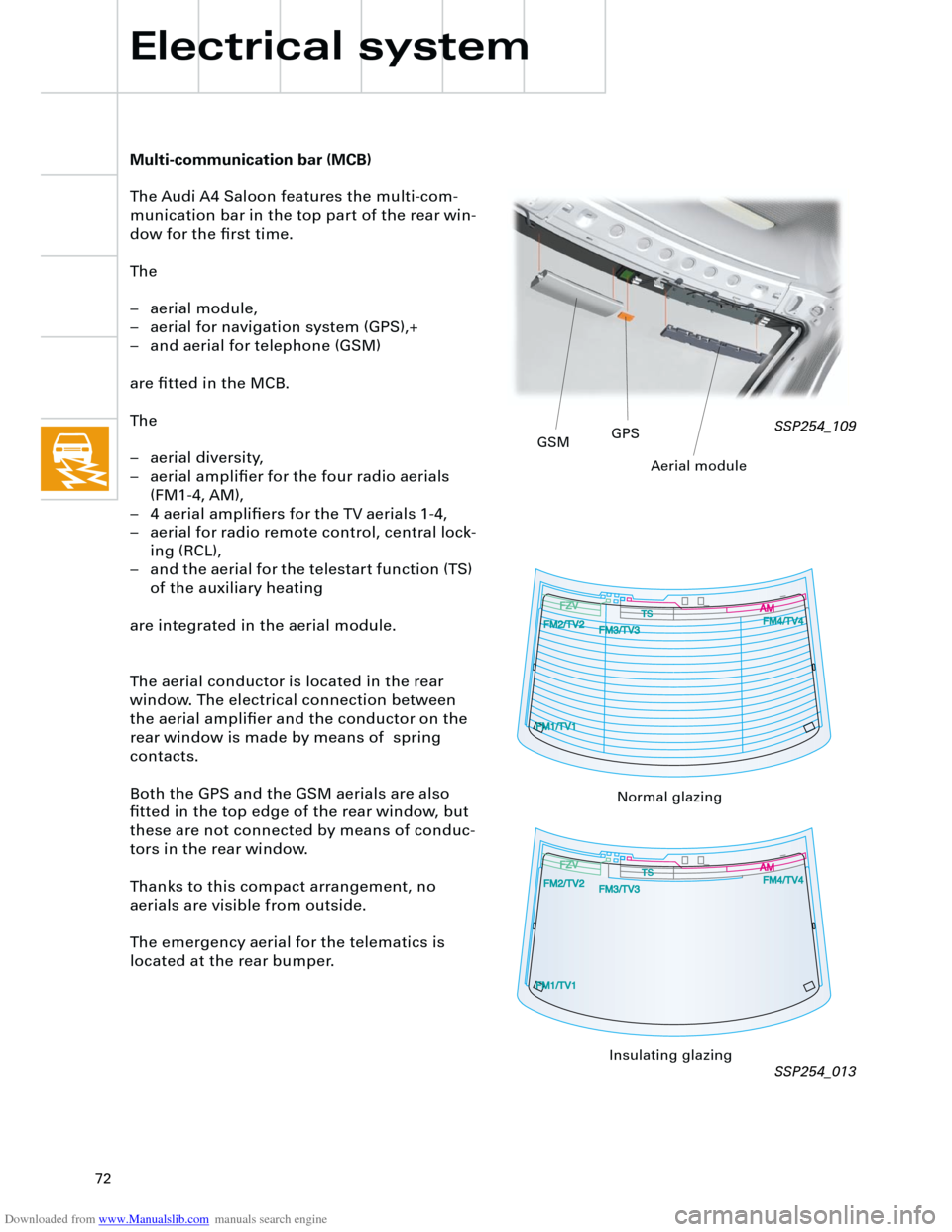
Multi-communication bar (MCB)
The Audi A4 Saloon features the multi-com-
munication bar in the top part of the rear win-
dow for the first time.
The
– aerial module,
– aerial for navigation system (GPS),+
– and aerial for telephone (GSM)
are fitted in the MCB.
The
– aerial diversity,
– aerial amplifier for the four radio aerials
(FM1-4, AM),
– 4 aerial amplifiers for the TV aerials 1-4,
– aerial for radio remote control, central lock-
ing (RCL),
– and the aerial for the telestart function (TS)
of the auxiliary heating
are integrated in the aerial module.
The aerial conductor is located in the rear
window. The electrical connection between
the aerial amplifier and the conductor on the
rear window is made by means of spring
contacts.
Both the GPS and the GSM aerials are also
fitted in the top edge of the rear window, but
these are not connected by means of conduc-
tors in the rear window.
Thanks to this compact arrangement, no
aerials are visible from outside.
The emergency aerial for the telematics is
located at the rear bumper.
Electrical system
SSP254_109
SSP254_013
GSMGPS
Aerial module
Normal glazing
Insulating glazing