2001 AUDI A4 wiring
[x] Cancel search: wiringPage 17 of 88
Downloaded from www.Manualslib.com manuals search engine
17
Crash signal processing
There are two separate crash signal outputs:
One crash signal is output via the conven-
tional wiring and triggers the following func-
tions:
– Transmitting an emergency call via the
control unit for telephone/telematics J526
(optional)
– unlocking the vehicle,
– Switch on interior light
(switch must be set to door contact),
– switching on hazard warning lights via the
central convenience electronics J393.
The auxiliary heater J162 (optional) is
switched off by the central convenience
electronics J393 via a CAN convenience
message.
The second crash signal output functions via
the convenience CAN bus, which switches off
the engine fuel supply via the engine control
unit J220.
Page 45 of 88
Downloaded from www.Manualslib.com manuals search engine
45
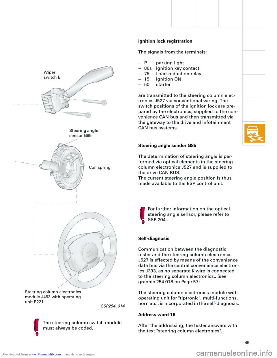
Steering angle sender G85
The determination of steering angle is per-
formed via optical elements in the steering
column electronics J527 and is supplied to
the drive CAN BUS.
The current steering angle position is thus
made available to the ESP control unit.
The steering column switch module
must always be coded.
For further information on the optical
steering angle sensor, please refer to
SSP 204.
Self-diagnosis
Communication between the diagnostic
tester and the steering column electronics
J527 is effected by means of the convenience
data bus via the central convenience electron-
ics J393, as no separate K wire is connected
to the steering column electronics.. (see
graphic 254 018 on Page 57)
The steering column electronics module with
operating unit for "tiptronic", multi-functions,
horn etc., is incorporated in the self-diagnosis.
Address word 16
After the addressing, the tester answers with
the text "steering column electronics".
Wiper
switch E
Steering angle
sensor G85
Steering column electronics
module J453 with operating
unit E221
Ignition lock registration
The signals from the terminals:
– P parking light
– 86s ignition key contact
– 75 Load-reduction relay
– 15 ignition ON
– 50 starter
are transmitted to the steering column elec-
tronics J527 via conventional wiring. The
switch positions of the ignition lock are pre-
pared by the electronics, supplied to the con-
venience CAN bus and then transmitted via
the gateway to the drive and infotainment
CAN bus systems.
Coil spring
RT
SSP254_014
Page 49 of 88
Downloaded from www.Manualslib.com manuals search engine
49
There are three control unit versions:
– "lowline" for the standard version
– "lowline" for vehicles with headlight
washer system
– "highline" for vehicles with driver informa-
tion system
The following functions are available with the
"lowline" version:
– Wash/wipe control and interval
– Hazard warning and turn signal control
– Actuation of horn and load-reduction relay
– Parking light left/right
– Side light left/right
– Main beam left/right and headlight flasher
– Number plate lightThe "highline" version implements the driver
information system function and also
performs the following control functions:
– Driving light and dipped beam left/right,
– Fog lights and rear lights,
– Reversing lights,
– Brake lights
with separate outputs to each of the individ-
ual consumers.
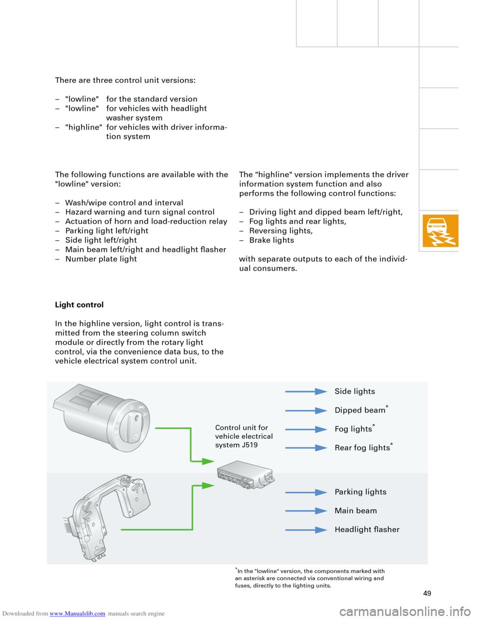
Light control
In the highline version, light control is trans-
mitted from the steering column switch
module or directly from the rotary light
control, via the convenience data bus, to the
vehicle electrical system control unit.
Parking lights
Main beam
Headlight flasher Side lights
Dipped beam
*
Fog lights
*
Rear fog lights
*
*
In the "lowline" version, the components marked with
an asterisk are connected via conventional wiring and
fuses, directly to the lighting units.
Control unit for
vehicle electrical
system J519
Page 57 of 88
Downloaded from www.Manualslib.com manuals search engine
57
Control unit for trailer recognition J345
A separate control unit is required for trailer
operation. This transmits the vehicle lighting
system convenience CAN messages from the
vehicle electrical system control unit to the
trailer lights. A parallel link from the trailer
socket to the vehicle wiring would result in
fault detection via the microprocessor in the
vehicle electrical system control unit.
The diagnostic function of the control unit for
trailer recognition is performed via the
vehicle electrical system control unit J519,
address word 09.
In the case of faulty communication
between the control unit for trailer recog-
nition and the vehicle electrical system
control unit, the rear lights are actuated
as a warning signal.
RT
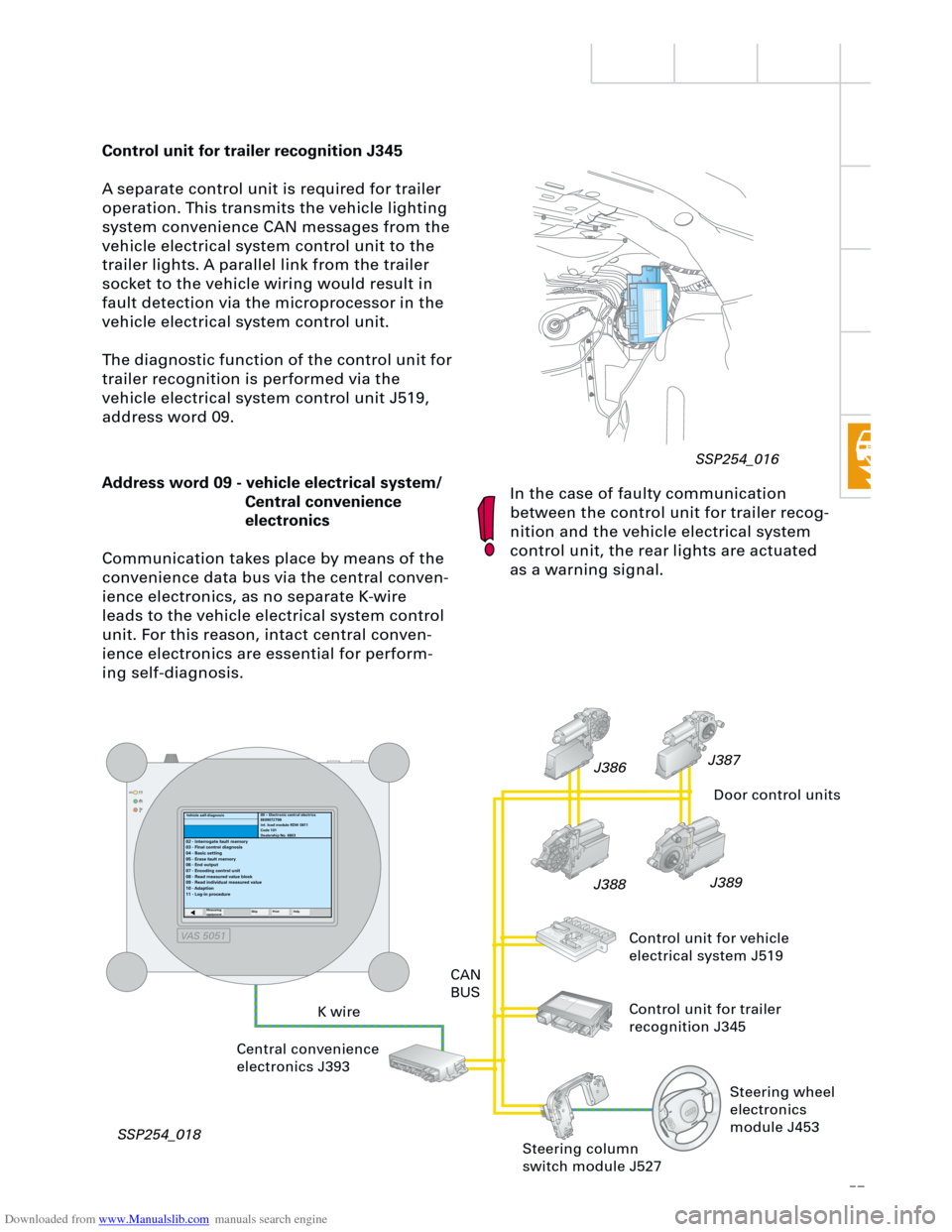
Address word 09 - vehicle electrical system/
Central convenience
electronics
Communication takes place by means of the
convenience data bus via the central conven-
ience electronics, as no separate K-wire
leads to the vehicle electrical system control
unit. For this reason, intact central conven-
ience electronics are essential for perform-
ing self-diagnosis.
K wireCAN
BUS
Central convenience
electronics J393
SSP254_018J389
J388J387
J386
Door control units
Control unit for vehicle
electrical system J519
Control unit for trailer
recognition J345
09 – Electronic central electrics
8E0907279B
int. load module RDW 0811
Code 101
Dealership No. 6803
02 - Interrogate fault memory
03 - Final control diagnosis
04 - Basic setting
05 - Erase fault memory
06 - End output
07 - Encoding control unit
08 - Read measured value block
09 - Read individual measured value
10 - Adaption
11 - Log-in procedure
Measuring
equipmentSkip PrintHelp
Steering column
switch module J527
Vehicle self-diagnosis
Steering wheel
electronics
module J453
SSP254_016
VAS 5051
Page 68 of 88
Downloaded from www.Manualslib.com manuals search engine
68
Example:
If the radio is switched on with the ignition
key (S-contact) this requires the exchange of
data between three control units:
– Steering column electronics,
– dash panel insert (gateway) and
– radio.
If the radio does not switch on,
– the signal input in the steering column
electronics (terminal 86S),
– communication between the steering col-
umn electronics and the dash panel
(convenience data bus) and
– communication between the dash panel
and the radio
(data bus information system)
must be checked.
Diagnostics
For diagnosis of radio systems concert II and
symphony II, current consumption of aerial
diversity is monitored via the intermittent
frequency (IF) wiring.
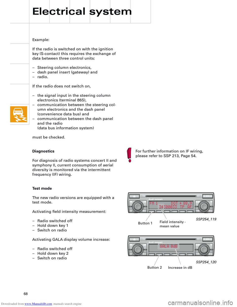
Test mode
The new radio versions are equipped with a
test mode.
Activating field intensity measurement:
– Radio switched off
– Hold down key 1
– Switch on radio
Activating GALA display volume increase:
– Radio switched off
– Hold down key 2
– Switch on radio
Electrical system
SSP254_119
SSP254_120
Field intensity -
mean value
Increase in dB Button 1
Button 2
For further information on IF wiring,
please refer to SSP 213, Page 54.
FM 1 DOT + 88.9
34300033 TP AF
GALA 0dB
Page 73 of 88
Downloaded from www.Manualslib.com manuals search engine
73
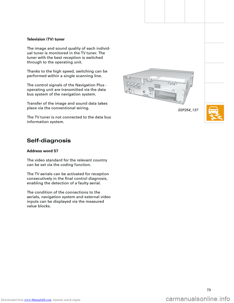
Television (TV) tuner
The image and sound quality of each individ-
ual tuner is monitored in the TV tuner. The
tuner with the best reception is switched
through to the operating unit.
Thanks to the high speed, switching can be
performed within a single scanning line.
The control signals of the Navigation Plus -
operating unit are transmitted via the data
bus system of the navigation system.
Transfer of the image and sound data takes
place via the conventional wiring.
The TV tuner is not connected to the data bus
information system.
Self-diagnosis
Address word 57
The video standard for the relevant country
can be set via the coding function.
The TV aerials can be activated for reception
consecutively in the final control diagnosis,
enabling the detection of a faulty aerial.
The condition of the connections to the
aerials, navigation system and external video
inputs can be displayed via the measured
value blocks.
SSP254_137