Page 38 of 88
Downloaded from www.Manualslib.com manuals search engine
38
Electrical system
NOX sensor
(USA only) Diagnosis system
CAN BUS networking
The ignition switch signals and the
control buttons for multifunction
and "tiptronic" steering wheel are
registered via the steering column
electronics.
G85
J162J502
R99
J401
Gate-
way
J220
J234
J387 J386
J388 J389
J393 J217
J104
J453 J446
J402 E87
J519
J136 J345J526J499 J507
J527
J285
R94
TRACK
SEEK
CD CDC
AM
FM1DOLBY SYSTEM2
12
TA P EPLAY SDEBASS MIDDLE TREBLE BALANCE FADER123456
EJECTAudi symphony
AS
TP
RDS
RANDOM FR FF
TUNE SCAN
EJECT
R
J527
R
T+-
Page 40 of 88
Downloaded from www.Manualslib.com manuals search engine
40
Electrical system
Setting buttons for digital clock,
date and instrument illuminationAuto-check system
Call-up button for
service interval
indicatorReset button for trip
recorder
Dash panel insert
There are two dash panel insert versions:
– "lowline"
– "highline"
The "highline" version is equipped with a
high-quality colour display for the driver infor-
mation system and is installed in vehicles
with navigation systems as well as telematics.The dash panel insert of the new Audi A4 is
equipped with
– the gateway for linking the three data bus
systems: drive, convenience, information
– and the immobiliser III.
Cruise control system ON
SSP254_012
Page 44 of 88

Downloaded from www.Manualslib.com manuals search engine
44
Electrical system
Steering column switch
module
Due to the compact design of the newly
developed steering column switch module, it
was possible to minimise the amount of wir-
ing necessary and the space requirements.
A self-diagnosis facility for the steering col-
umn switch is now available with new switch
module.
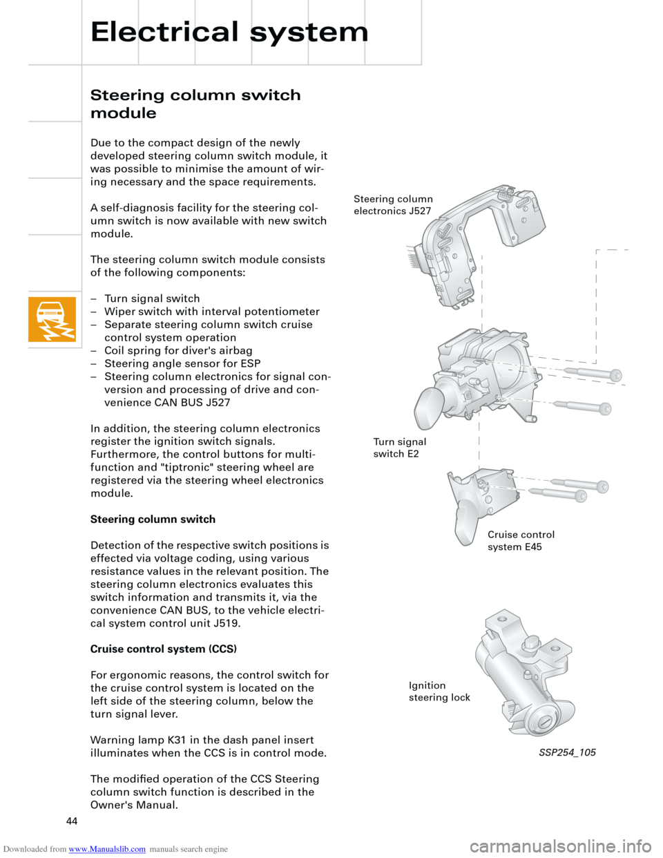
The steering column switch module consists
of the following components:
– Turn signal switch
– Wiper switch with interval potentiometer
– Separate steering column switch cruise
control system operation
– Coil spring for diver's airbag
– Steering angle sensor for ESP
– Steering column electronics for signal con-
version and processing of drive and con-
venience CAN BUS J527
In addition, the steering column electronics
register the ignition switch signals.
Furthermore, the control buttons for multi-
function and "tiptronic" steering wheel are
registered via the steering wheel electronics
module.
Steering column switch
Detection of the respective switch positions is
effected via voltage coding, using various
resistance values in the relevant position. The
steering column electronics evaluates this
switch information and transmits it, via the
convenience CAN BUS, to the vehicle electri-
cal system control unit J519.
Cruise control system (CCS)
For ergonomic reasons, the control switch for
the cruise control system is located on the
left side of the steering column, below the
turn signal lever.
Warning lamp K31 in the dash panel insert
illuminates when the CCS is in control mode.
The modified operation of the CCS Steering
column switch function is described in the
Owner's Manual.
Cruise control
system E45
Ignition
steering lock Steering column
electronics J527
Turn signal
switch E2
SSP254_105