Page 34 of 88

Downloaded from www.Manualslib.com manuals search engine
34
Running gear
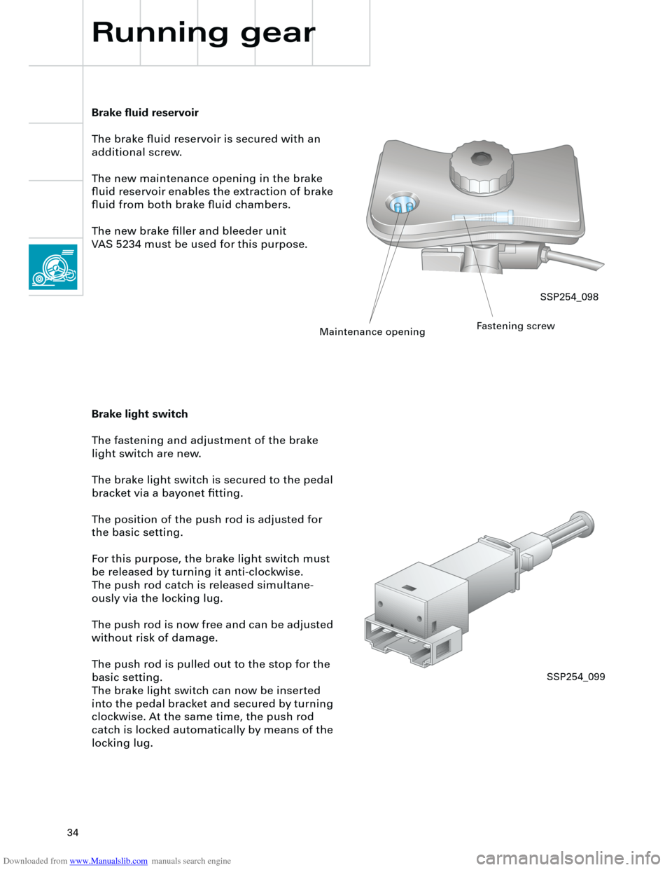
Brake fluid reservoir
The brake fluid reservoir is secured with an
additional screw.
The new maintenance opening in the brake
fluid reservoir enables the extraction of brake
fluid from both brake fluid chambers.
The new brake filler and bleeder unit
VAS 5234 must be used for this purpose.
Brake light switch
The fastening and adjustment of the brake
light switch are new.
The brake light switch is secured to the pedal
bracket via a bayonet fitting.
The position of the push rod is adjusted for
the basic setting.
For this purpose, the brake light switch must
be released by turning it anti-clockwise.
The push rod catch is released simultane-
ously via the locking lug.
The push rod is now free and can be adjusted
without risk of damage.
The push rod is pulled out to the stop for the
basic setting.
The brake light switch can now be inserted
into the pedal bracket and secured by turning
clockwise. At the same time, the push rod
catch is locked automatically by means of the
locking lug.
SSP254_098
Maintenance openingFastening screw
SSP254_099
Page 40 of 88
Downloaded from www.Manualslib.com manuals search engine
40
Electrical system
Setting buttons for digital clock,
date and instrument illuminationAuto-check system
Call-up button for
service interval
indicatorReset button for trip
recorder
Dash panel insert
There are two dash panel insert versions:
– "lowline"
– "highline"
The "highline" version is equipped with a
high-quality colour display for the driver infor-
mation system and is installed in vehicles
with navigation systems as well as telematics.The dash panel insert of the new Audi A4 is
equipped with
– the gateway for linking the three data bus
systems: drive, convenience, information
– and the immobiliser III.
Cruise control system ON
SSP254_012
Page 41 of 88
Downloaded from www.Manualslib.com manuals search engine
41
In order to ensure good signal reception for
the radio clock, the receiver is installed in the
rear bumper bar. User prompt in the centre display via the con-
trol switch in the centre console, is only avail-
able in vehicles with
– navigation system ("highline" version only)
and/or
– telematics and/or
– auxiliary heater and/or
– tyre pressure monitoring.
The optional driver information system
includes the following functions:
– radio clock
– auto-check system
– on-board computer.
The km range is indicated in the basic ver-
sion.
Ear
th
Radio signal
+ 5
V
SSP254_104
SSP254_108
Page 54 of 88

Downloaded from www.Manualslib.com manuals search engine
54
5 V/Div.=10 ms/Div.
0 T
Electrical system
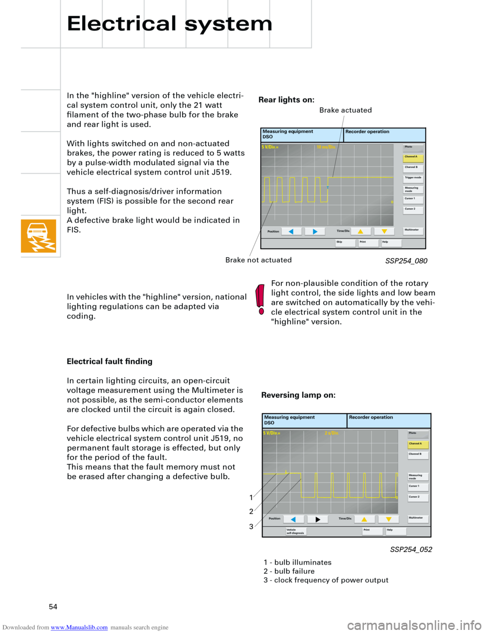
In the "highline" version of the vehicle electri-
cal system control unit, only the 21 watt
filament of the two-phase bulb for the brake
and rear light is used.
With lights switched on and non-actuated
brakes, the power rating is reduced to 5 watts
by a pulse-width modulated signal via the
vehicle electrical system control unit J519.
Thus a self-diagnosis/driver information
system (FIS) is possible for the second rear
light.
A defective brake light would be indicated in
FIS.
In vehicles with the "highline" version, national
lighting regulations can be adapted via
coding.For non-plausible condition of the rotary
light control, the side lights and low beam
are switched on automatically by the vehi-
cle electrical system control unit in the
"highline" version.
SSP254_080
Measuring equipment
DSORecorder operation
Photo
Channel A
Channel B
Measuring
mode
Cursor 1
Cursor 2
Multimeter
Help Print
PositionTime/Div.
Trigger mode
Skip
Brake not actuatedBrake actuated
Rear lights on:
5 V/Div.=2 s/Div.
0
Electrical fault finding
In certain lighting circuits, an open-circuit
voltage measurement using the Multimeter is
not possible, as the semi-conductor elements
are clocked until the circuit is again closed.
For defective bulbs which are operated via the
vehicle electrical system control unit J519, no
permanent fault storage is effected, but only
for the period of the fault.
This means that the fault memory must not
be erased after changing a defective bulb.
Measuring equipment
DSORecorder operation
Photo
Channel A
Channel B
Measuring
mode
Cursor 1
Cursor 2
Multimeter
Help Print Ve h i c l e
self-diagnosis
Position Time/Div.
Reversing lamp on:
1 - bulb illuminates
2 - bulb failure
3 - clock frequency of power output
1
2
3
SSP254_052