Page 11 of 88

Downloaded from www.Manualslib.com manuals search engine
11
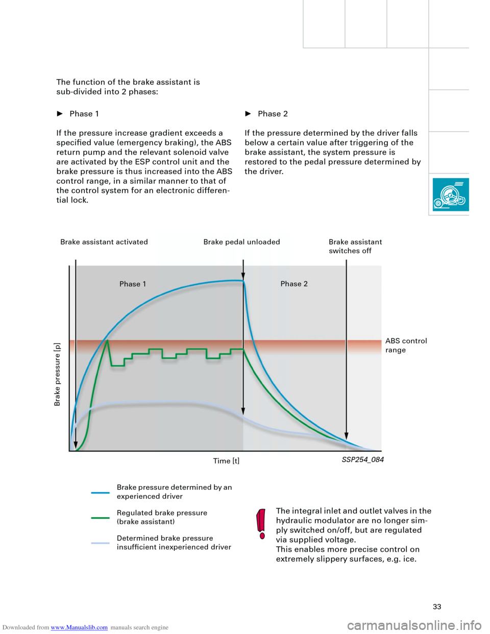
Luggage compartment lid
The luggage compartment lid should always
be operated via the radio remote control.
The lock cylinder for the luggage compart-
ment lid is integrated into the handle.
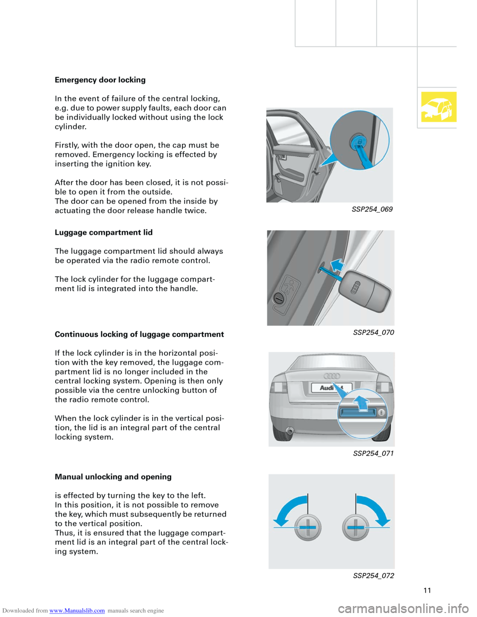
Emergency door locking
In the event of failure of the central locking,
e.g. due to power supply faults, each door can
be individually locked without using the lock
cylinder.
Firstly, with the door open, the cap must be
removed. Emergency locking is effected by
inserting the ignition key.
After the door has been closed, it is not possi-
ble to open it from the outside.
The door can be opened from the inside by
actuating the door release handle twice.
Continuous locking of luggage compartment
If the lock cylinder is in the horizontal posi-
tion with the key removed, the luggage com-
partment lid is no longer included in the
central locking system. Opening is then only
possible via the centre unlocking button of
the radio remote control.
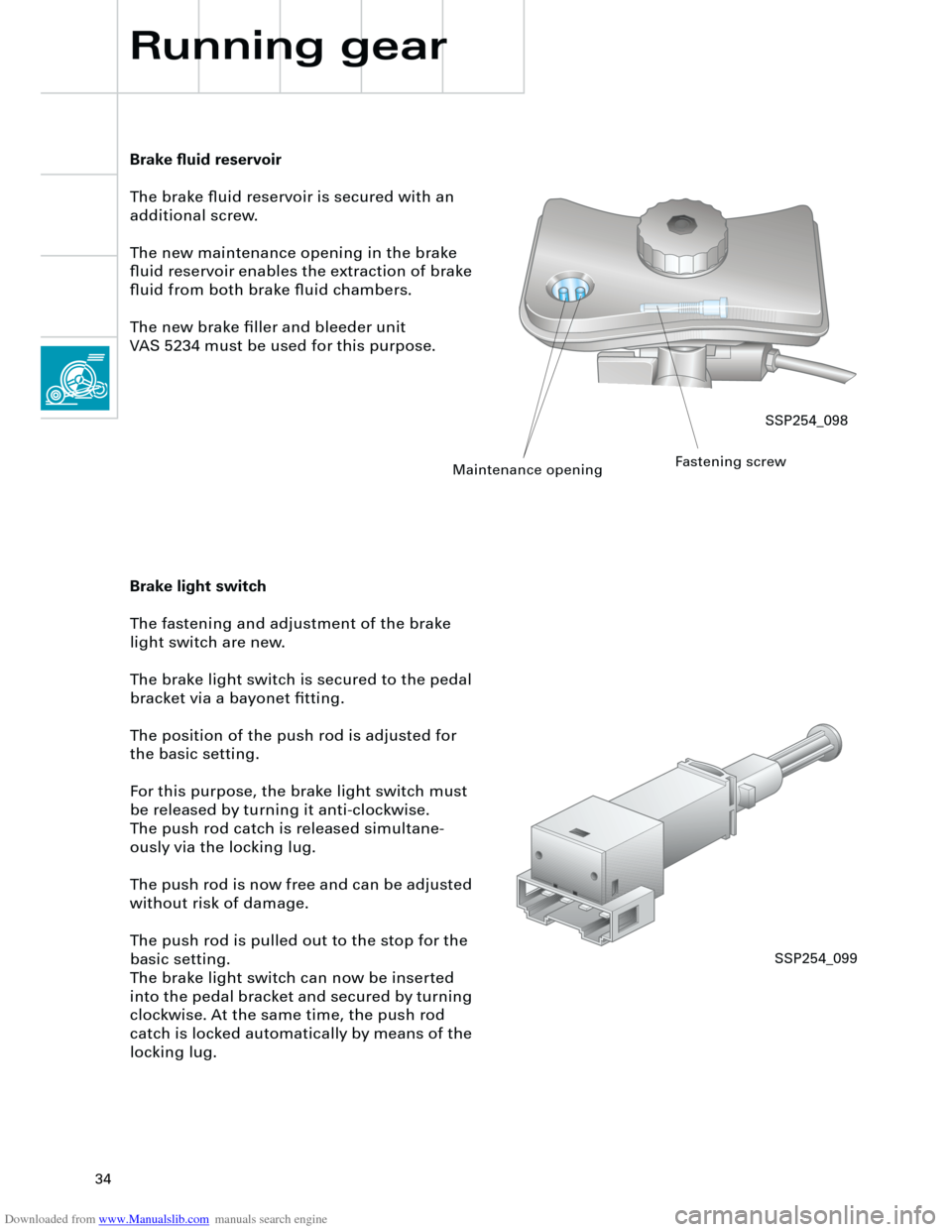
When the lock cylinder is in the vertical posi-
tion, the lid is an integral part of the central
locking system.
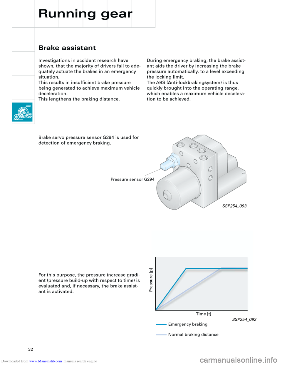
Manual unlocking and opening
is effected by turning the key to the left.
In this position, it is not possible to remove
the key, which must subsequently be returned
to the vertical position.
Thus, it is ensured that the luggage compart-
ment lid is an integral part of the central lock-
ing system.
SSP254_069
SSP254_070
SSP254_071
SSP254_072
Page 16 of 88
Downloaded from www.Manualslib.com manuals search engine
16
Occupant protection
Front belt attachment
Belt lock and strap fastenings are perma-
nently connected to the seat frame. Thus, in
conjunction with the seat belt height adjuster,
an optimal belt fitting can be achieved for
each seat position.
Deactivation of passenger airbag
Deactivation of the passenger airbag is only
possible via the key switch. In the Audi A4, the
passenger's side airbag is also deactivated.
Deactivation via the diagnostic tester is not
possible.
If a customer requires the deactivation func-
tion where a key switch is not fitted, this can
only be achieved by retrofitting the key switch
and airbag OFF lamp and by re-encoding of
the airbag control unit.
Front head restraints
In order to offer a high degree of occupant
protection in conjunction with the seat belt
and airbag, the front head restraints have
been supplemented by an integral locking
mechanism.
aa
aaa
a
SSP254_011
SSP254_102SSP254_101
Page 17 of 88
Downloaded from www.Manualslib.com manuals search engine
17
Crash signal processing
There are two separate crash signal outputs:
One crash signal is output via the conven-
tional wiring and triggers the following func-
tions:
– Transmitting an emergency call via the
control unit for telephone/telematics J526
(optional)
– unlocking the vehicle,
– Switch on interior light
(switch must be set to door contact),
– switching on hazard warning lights via the
central convenience electronics J393.
The auxiliary heater J162 (optional) is
switched off by the central convenience
electronics J393 via a CAN convenience
message.
The second crash signal output functions via
the convenience CAN bus, which switches off
the engine fuel supply via the engine control
unit J220.
Page 32 of 88

Downloaded from www.Manualslib.com manuals search engine
32
Brake assistant
Investigations in accident research have
shown, that the majority of drivers fail to ade-
quately actuate the brakes in an emergency
situation.
This results in insufficient brake pressure
being generated to achieve maximum vehicle
deceleration.
This lengthens the braking distance.During emergency braking, the brake assist-
ant aids the driver by increasing the brake
pressure automatically, to a level exceeding
the locking limit.
The ABS (
A
nti-lock
b
raking
s
ystem) is thus
quickly brought into the operating range,
which enables a maximum vehicle decelera-
tion to be achieved.
Brake servo pressure sensor G294 is used for
detection of emergency braking.
Time [t]
Pressure [p]
For this purpose, the pressure increase gradi-
ent (pressure build-up with respect to time) is
evaluated and, if necessary, the brake assist-
ant is activated.
SSP254_093
Emergency braking
Normal braking distance
Pressure sensor G294
Running gear
SSP254_092
Page 33 of 88

Downloaded from www.Manualslib.com manuals search engine
33
• Phase 2
If the pressure determined by the driver falls
below a certain value after triggering of the
brake assistant, the system pressure is
restored to the pedal pressure determined by
the driver. The function of the brake assistant is
sub-divided into 2 phases:
• Phase 1
If the pressure increase gradient exceeds a
specified value (emergency braking), the ABS
return pump and the relevant solenoid valve
are activated by the ESP control unit and the
brake pressure is thus increased into the ABS
control range, in a similar manner to that of
the control system for an electronic differen-
tial lock.
The integral inlet and outlet valves in the
hydraulic modulator are no longer sim-
ply switched on/off, but are regulated
via supplied voltage.
This enables more precise control on
extremely slippery surfaces, e.g. ice.
SSP254_084
Time [t]
Brake pressure [p]
Brake pressure determined by an
experienced driver
Regulated brake pressure
(brake assistant)
Determined brake pressure
insufficient inexperienced driver Brake assistant activated Brake pedal unloaded Brake assistant
switches off
Phase 1Phase 2
ABS control
range
Page 34 of 88

Downloaded from www.Manualslib.com manuals search engine
34
Running gear
Brake fluid reservoir
The brake fluid reservoir is secured with an
additional screw.
The new maintenance opening in the brake
fluid reservoir enables the extraction of brake
fluid from both brake fluid chambers.
The new brake filler and bleeder unit
VAS 5234 must be used for this purpose.
Brake light switch
The fastening and adjustment of the brake
light switch are new.
The brake light switch is secured to the pedal
bracket via a bayonet fitting.
The position of the push rod is adjusted for
the basic setting.
For this purpose, the brake light switch must
be released by turning it anti-clockwise.
The push rod catch is released simultane-
ously via the locking lug.
The push rod is now free and can be adjusted
without risk of damage.
The push rod is pulled out to the stop for the
basic setting.
The brake light switch can now be inserted
into the pedal bracket and secured by turning
clockwise. At the same time, the push rod
catch is locked automatically by means of the
locking lug.
SSP254_098
Maintenance openingFastening screw
SSP254_099
Page 40 of 88
Downloaded from www.Manualslib.com manuals search engine
40
Electrical system
Setting buttons for digital clock,
date and instrument illuminationAuto-check system
Call-up button for
service interval
indicatorReset button for trip
recorder
Dash panel insert
There are two dash panel insert versions:
– "lowline"
– "highline"
The "highline" version is equipped with a
high-quality colour display for the driver infor-
mation system and is installed in vehicles
with navigation systems as well as telematics.The dash panel insert of the new Audi A4 is
equipped with
– the gateway for linking the three data bus
systems: drive, convenience, information
– and the immobiliser III.
Cruise control system ON
SSP254_012
Page 41 of 88
Downloaded from www.Manualslib.com manuals search engine
41
In order to ensure good signal reception for
the radio clock, the receiver is installed in the
rear bumper bar. User prompt in the centre display via the con-
trol switch in the centre console, is only avail-
able in vehicles with
– navigation system ("highline" version only)
and/or
– telematics and/or
– auxiliary heater and/or
– tyre pressure monitoring.
The optional driver information system
includes the following functions:
– radio clock
– auto-check system
– on-board computer.
The km range is indicated in the basic ver-
sion.
Ear
th
Radio signal
+ 5
V
SSP254_104
SSP254_108