Page 26 of 88
Downloaded from www.Manualslib.com manuals search engine
26
The suspension strut mounting is of the bulky
rubber bearing construction.
It consists of two functional components:
– The inner part forms the connection to the
piston rod.
– The larger outer part provides for acoustic
insulation of the shock absorber.
Axles
Four-link front axle
The thorough further development of the
light-weight construction resulted in a weight
reduction of approx. 8.5 kg at the front axle.
In addition to all transverse links, the pivot
bearing is now also made of aluminium.
The wheel bearing is attached to the pivot
bearing via four bolts. The wheel hub can be
pressed in and out.
Running gear
SSP254_087
Aluminium pivot bearing Aluminium mounting bracket
Aluminium
spring plate
Shock absorber valves
SSP254_086
SSP254_085
Page 29 of 88

Downloaded from www.Manualslib.com manuals search engine
29
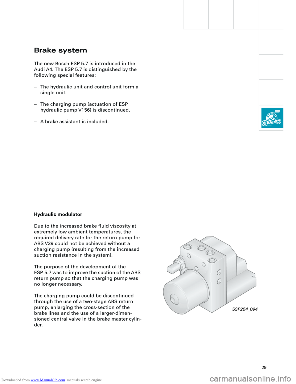
Brake system
The new Bosch ESP 5.7 is introduced in the
Audi A4. The ESP 5.7 is distinguished by the
following special features:
– The hydraulic unit and control unit form a
single unit.
– The charging pump (actuation of ESP
hydraulic pump V156) is discontinued.
– A brake assistant is included.
Hydraulic modulator
Due to the increased brake fluid viscosity at
extremely low ambient temperatures, the
required delivery rate for the return pump for
ABS V39 could not be achieved without a
charging pump (resulting from the increased
suction resistance in the system).
The purpose of the development of the
ESP 5.7 was to improve the suction of the ABS
return pump so that the charging pump was
no longer necessary.
The charging pump could be discontinued
through the use of a two-stage ABS return
pump, enlarging the cross-section of the
brake lines and the use of a larger-dimen-
sioned central valve in the brake master cylin-
der.
SSP254_094
Page 30 of 88
Downloaded from www.Manualslib.com manuals search engine
30
UTUTOTOTUT
UTUTOTOTUT
Running gear
The graphic shows a comparison of the
suction volumes of both pump versions.
In the single-stage ABS return pump, the
entire suction volume must be drawn in and
flow through the suction line during one
piston stroke (piston stroke from TDC to BDC). The suction pressure is correspondingly high
and increases with increasing viscosity.
Cavitation and the associated drop in
performance on the pressure side, are the
results.
Single-stage ABS return pump
Suction volumes
SSP254_095
Suction volumes
Page 31 of 88

Downloaded from www.Manualslib.com manuals search engine
31
UTUTOTOT
UTUTOTOT
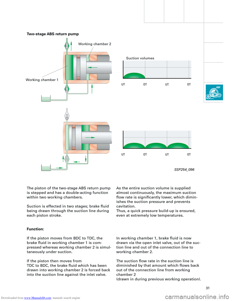
The piston of the two-stage ABS return pump
is stepped and has a double-acting function
within two working chambers.
Suction is effected in two stages; brake fluid
being drawn through the suction line during
each piston stroke.
Function:
If the piston moves from BDC to TDC, the
brake fluid in working chamber 1 is com-
pressed whereas working chamber 2 is simul-
taneously under suction.
If the piston then moves from
TDC to BDC, the brake fluid which has been
drawn into working chamber 2 is forced back
into the suction line against the inlet valve.As the entire suction volume is supplied
almost continuously, the maximum suction
flow rate is significantly lower, which dimin-
ishes the suction pressure and prevents
cavitation.
Thus, a quick pressure build-up is ensured,
even at extremely low temperatures.
In working chamber 1, brake fluid is now
drawn via the open inlet valve, out of the suc-
tion line and out of the connection line to
working chamber 2.
The suction flow rate in the suction line is
diminished by that amount which flows back
out of the connection line from working
chamber 2
(drawn in during previous working operation).
Two-stage ABS return pump
Working chamber 1Working chamber 2
Suction volumes
SSP254_096
Page 32 of 88

Downloaded from www.Manualslib.com manuals search engine
32
Brake assistant
Investigations in accident research have
shown, that the majority of drivers fail to ade-
quately actuate the brakes in an emergency
situation.
This results in insufficient brake pressure
being generated to achieve maximum vehicle
deceleration.
This lengthens the braking distance.During emergency braking, the brake assist-
ant aids the driver by increasing the brake
pressure automatically, to a level exceeding
the locking limit.
The ABS (
A
nti-lock
b
raking
s
ystem) is thus
quickly brought into the operating range,
which enables a maximum vehicle decelera-
tion to be achieved.
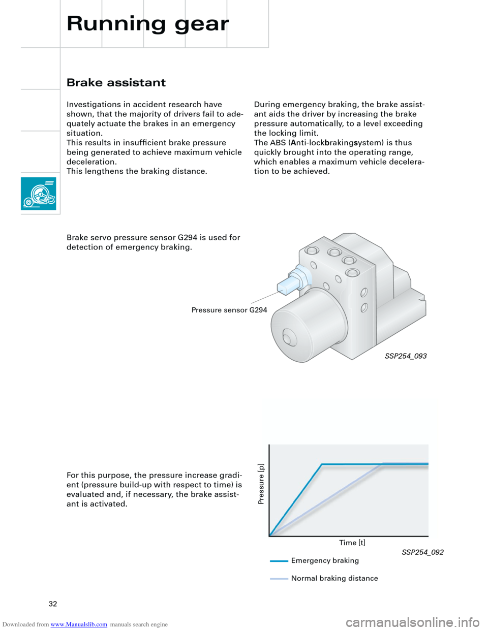
Brake servo pressure sensor G294 is used for
detection of emergency braking.
Time [t]
Pressure [p]
For this purpose, the pressure increase gradi-
ent (pressure build-up with respect to time) is
evaluated and, if necessary, the brake assist-
ant is activated.
SSP254_093
Emergency braking
Normal braking distance
Pressure sensor G294
Running gear
SSP254_092
Page 33 of 88

Downloaded from www.Manualslib.com manuals search engine
33
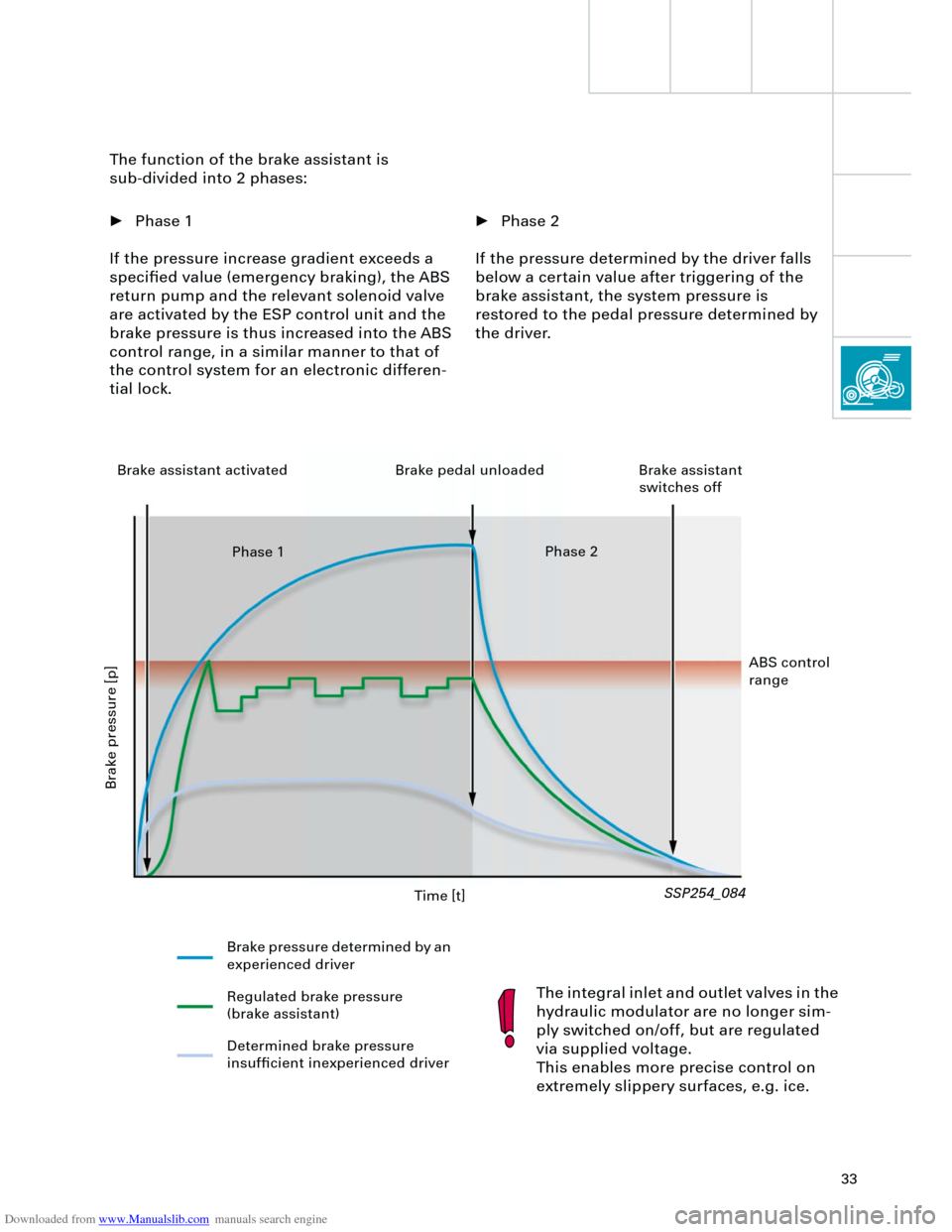
• Phase 2
If the pressure determined by the driver falls
below a certain value after triggering of the
brake assistant, the system pressure is
restored to the pedal pressure determined by
the driver. The function of the brake assistant is
sub-divided into 2 phases:
• Phase 1
If the pressure increase gradient exceeds a
specified value (emergency braking), the ABS
return pump and the relevant solenoid valve
are activated by the ESP control unit and the
brake pressure is thus increased into the ABS
control range, in a similar manner to that of
the control system for an electronic differen-
tial lock.
The integral inlet and outlet valves in the
hydraulic modulator are no longer sim-
ply switched on/off, but are regulated
via supplied voltage.
This enables more precise control on
extremely slippery surfaces, e.g. ice.
SSP254_084
Time [t]
Brake pressure [p]
Brake pressure determined by an
experienced driver
Regulated brake pressure
(brake assistant)
Determined brake pressure
insufficient inexperienced driver Brake assistant activated Brake pedal unloaded Brake assistant
switches off
Phase 1Phase 2
ABS control
range