Page 4 of 88
Downloaded from www.Manualslib.com manuals search engine
4
Introduction
Infinitely variable perfection
For the first time in this vehicle class, Audi
offers the infinitely variable "multitronic"
automatic gearbox for all front-wheel drive
versions.
The architecture of motion
Performance and smooth running
The engine programme of the new Audi A4
includes two petrol engines of a completely
new design, with aluminium housings.
The 2.0 litre 4-cylinder in-line engine with
96 kW (130 PS) and the 3.0 litre V6 with
162 kW (220 PS) fulfil the EU 4 emissions
standard.
A high degree of running smoothness is
achieved via balancer shafts.
The new light alloy running gear
With the four-link front axle, each wheel is
controlled by four aluminium transverse links.
The pivot bearings are also made from the
same light alloy.
The trapezium link rear axle for the quattro
drive system is also used in the front-wheel
drive models of the Audi A4.
Page 8 of 88
Downloaded from www.Manualslib.com manuals search engine
8
Body
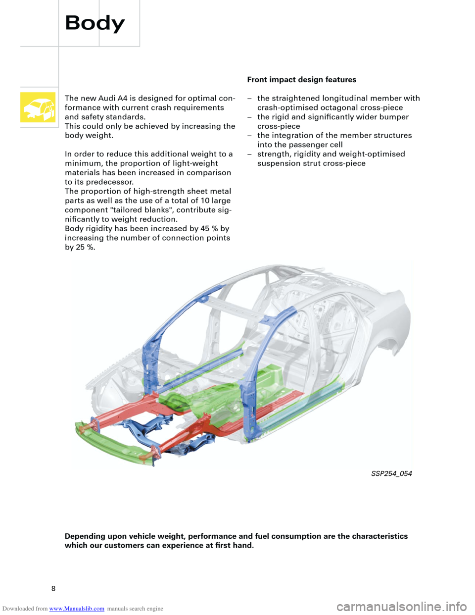
Front impact design features
– the straightened longitudinal member with
crash-optimised octagonal cross-piece
– the rigid and significantly wider bumper
cross-piece
– the integration of the member structures
into the passenger cell
– strength, rigidity and weight-optimised
suspension strut cross-piece The new Audi A4 is designed for optimal con-
formance with current crash requirements
and safety standards.
This could only be achieved by increasing the
body weight.
In order to reduce this additional weight to a
minimum, the proportion of light-weight
materials has been increased in comparison
to its predecessor.
The proportion of high-strength sheet metal
parts as well as the use of a total of 10 large
component "tailored blanks", contribute sig-
nificantly to weight reduction.
Body rigidity has been increased by 45 % by
increasing the number of connection points
by 25 %.
Depending upon vehicle weight, performance and fuel consumption are the characteristics
which our customers can experience at first hand.
SSP254_054
Page 17 of 88
Downloaded from www.Manualslib.com manuals search engine
17
Crash signal processing
There are two separate crash signal outputs:
One crash signal is output via the conven-
tional wiring and triggers the following func-
tions:
– Transmitting an emergency call via the
control unit for telephone/telematics J526
(optional)
– unlocking the vehicle,
– Switch on interior light
(switch must be set to door contact),
– switching on hazard warning lights via the
central convenience electronics J393.
The auxiliary heater J162 (optional) is
switched off by the central convenience
electronics J393 via a CAN convenience
message.
The second crash signal output functions via
the convenience CAN bus, which switches off
the engine fuel supply via the engine control
unit J220.
Page 26 of 88
Downloaded from www.Manualslib.com manuals search engine
26
The suspension strut mounting is of the bulky
rubber bearing construction.
It consists of two functional components:
– The inner part forms the connection to the
piston rod.
– The larger outer part provides for acoustic
insulation of the shock absorber.
Axles
Four-link front axle
The thorough further development of the
light-weight construction resulted in a weight
reduction of approx. 8.5 kg at the front axle.
In addition to all transverse links, the pivot
bearing is now also made of aluminium.
The wheel bearing is attached to the pivot
bearing via four bolts. The wheel hub can be
pressed in and out.
Running gear
SSP254_087
Aluminium pivot bearing Aluminium mounting bracket
Aluminium
spring plate
Shock absorber valves
SSP254_086
SSP254_085
Page 34 of 88
Downloaded from www.Manualslib.com manuals search engine
34
Running gear
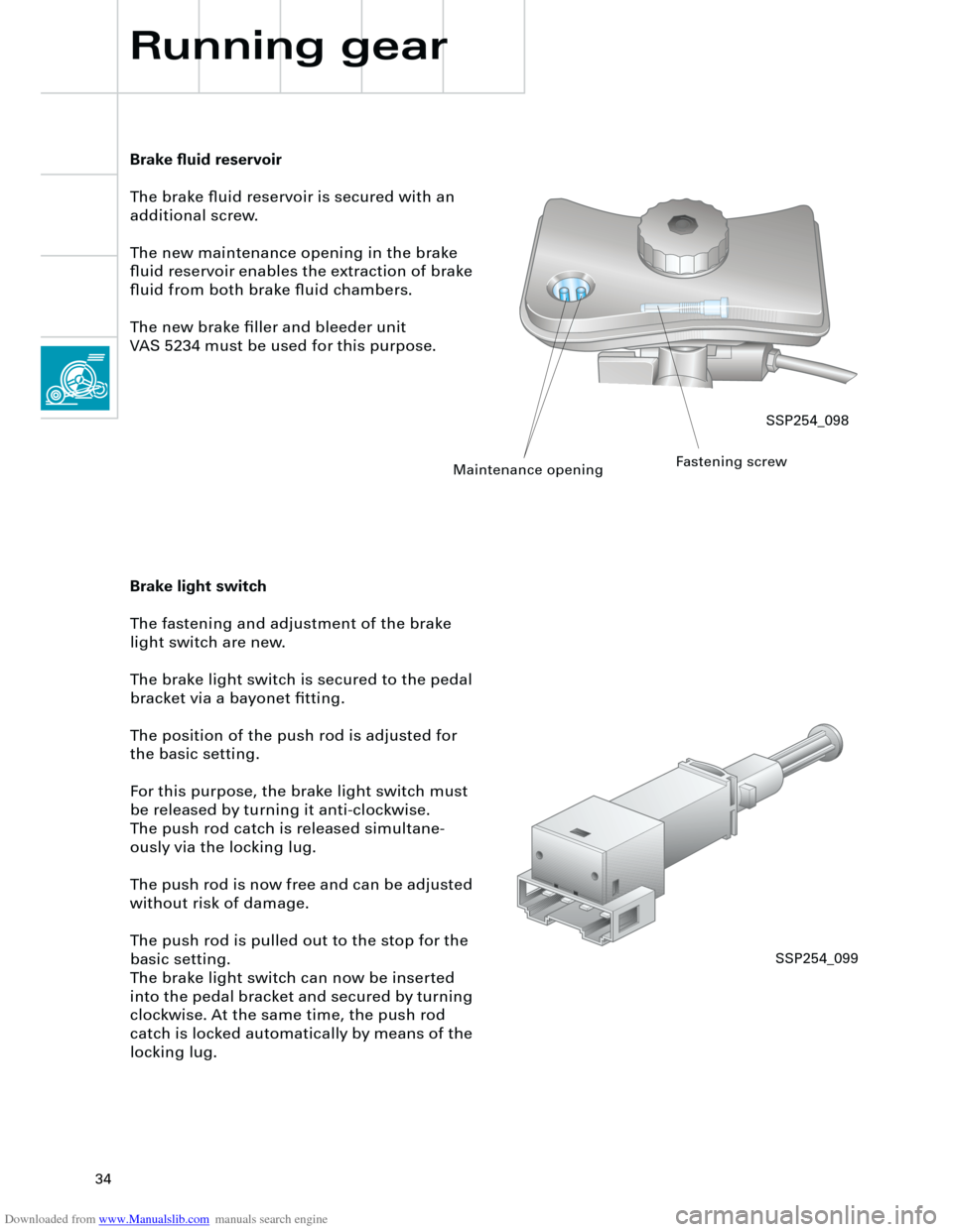
Brake fluid reservoir
The brake fluid reservoir is secured with an
additional screw.
The new maintenance opening in the brake
fluid reservoir enables the extraction of brake
fluid from both brake fluid chambers.
The new brake filler and bleeder unit
VAS 5234 must be used for this purpose.
Brake light switch
The fastening and adjustment of the brake
light switch are new.
The brake light switch is secured to the pedal
bracket via a bayonet fitting.
The position of the push rod is adjusted for
the basic setting.
For this purpose, the brake light switch must
be released by turning it anti-clockwise.
The push rod catch is released simultane-
ously via the locking lug.
The push rod is now free and can be adjusted
without risk of damage.
The push rod is pulled out to the stop for the
basic setting.
The brake light switch can now be inserted
into the pedal bracket and secured by turning
clockwise. At the same time, the push rod
catch is locked automatically by means of the
locking lug.
SSP254_098
Maintenance openingFastening screw
SSP254_099
Page 45 of 88
Downloaded from www.Manualslib.com manuals search engine
45
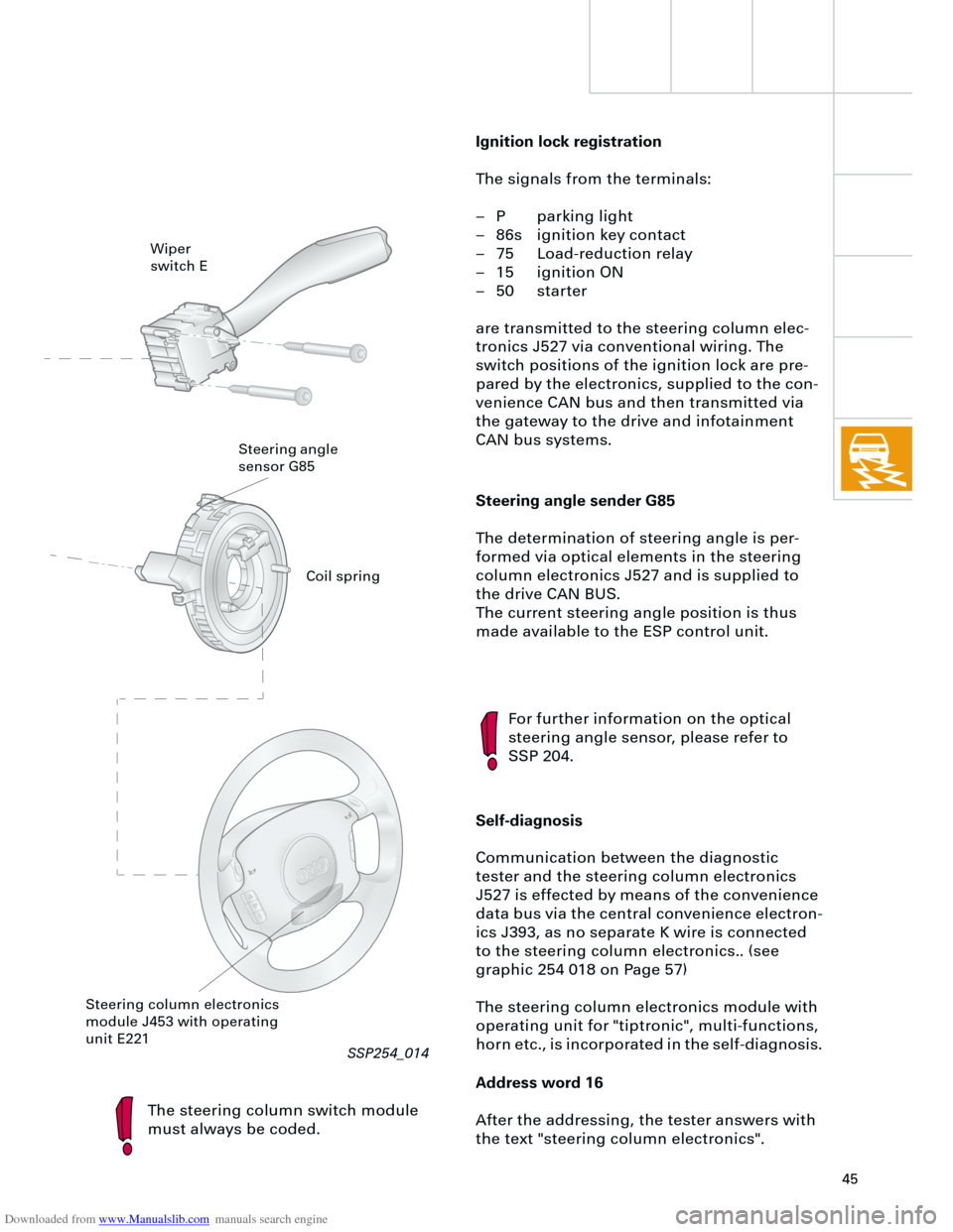
Steering angle sender G85
The determination of steering angle is per-
formed via optical elements in the steering
column electronics J527 and is supplied to
the drive CAN BUS.
The current steering angle position is thus
made available to the ESP control unit.
The steering column switch module
must always be coded.
For further information on the optical
steering angle sensor, please refer to
SSP 204.
Self-diagnosis
Communication between the diagnostic
tester and the steering column electronics
J527 is effected by means of the convenience
data bus via the central convenience electron-
ics J393, as no separate K wire is connected
to the steering column electronics.. (see
graphic 254 018 on Page 57)
The steering column electronics module with
operating unit for "tiptronic", multi-functions,
horn etc., is incorporated in the self-diagnosis.
Address word 16
After the addressing, the tester answers with
the text "steering column electronics".
Wiper
switch E
Steering angle
sensor G85
Steering column electronics
module J453 with operating
unit E221
Ignition lock registration
The signals from the terminals:
– P parking light
– 86s ignition key contact
– 75 Load-reduction relay
– 15 ignition ON
– 50 starter
are transmitted to the steering column elec-
tronics J527 via conventional wiring. The
switch positions of the ignition lock are pre-
pared by the electronics, supplied to the con-
venience CAN bus and then transmitted via
the gateway to the drive and infotainment
CAN bus systems.
Coil spring
RT
SSP254_014
Page 48 of 88
Downloaded from www.Manualslib.com manuals search engine
48
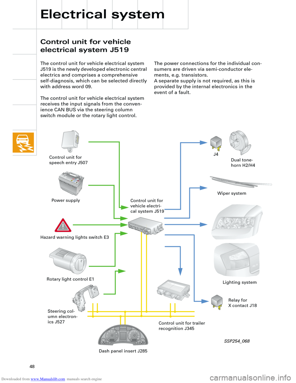
The control unit for vehicle electrical system
J519 is the newly developed electronic central
electrics and comprises a comprehensive
self-diagnosis, which can be selected directly
with address word 09.
The control unit for vehicle electrical system
receives the input signals from the conven-
ience CAN BUS via the steering column
switch module or the rotary light control.
Pb1J0 915 105 A 1J0 915 105 A
C C
The power connections for the individual con-
sumers are driven via semi-conductor ele-
ments, e.g. transistors.
A separate supply is not required, as this is
provided by the internal electronics in the
event of a fault.
J4
Dual tone-
horn H2/H4 Control unit for
speech entry J507
Power supply
Hazard warning lights switch E3
Steering col-
umn electron-
ics J527 Rotary light control E1
Wiper system
Lighting system
Dash panel insert J285Control unit for trailer
recognition J345 Control unit for
vehicle electri-
cal system J519
Relay for
X contact J18
Electrical system
Control unit for vehicle
electrical system J519
SSP254_068
Page 49 of 88
Downloaded from www.Manualslib.com manuals search engine
49
There are three control unit versions:
– "lowline" for the standard version
– "lowline" for vehicles with headlight
washer system
– "highline" for vehicles with driver informa-
tion system
The following functions are available with the
"lowline" version:
– Wash/wipe control and interval
– Hazard warning and turn signal control
– Actuation of horn and load-reduction relay
– Parking light left/right
– Side light left/right
– Main beam left/right and headlight flasher
– Number plate lightThe "highline" version implements the driver
information system function and also
performs the following control functions:
– Driving light and dipped beam left/right,
– Fog lights and rear lights,
– Reversing lights,
– Brake lights
with separate outputs to each of the individ-
ual consumers.
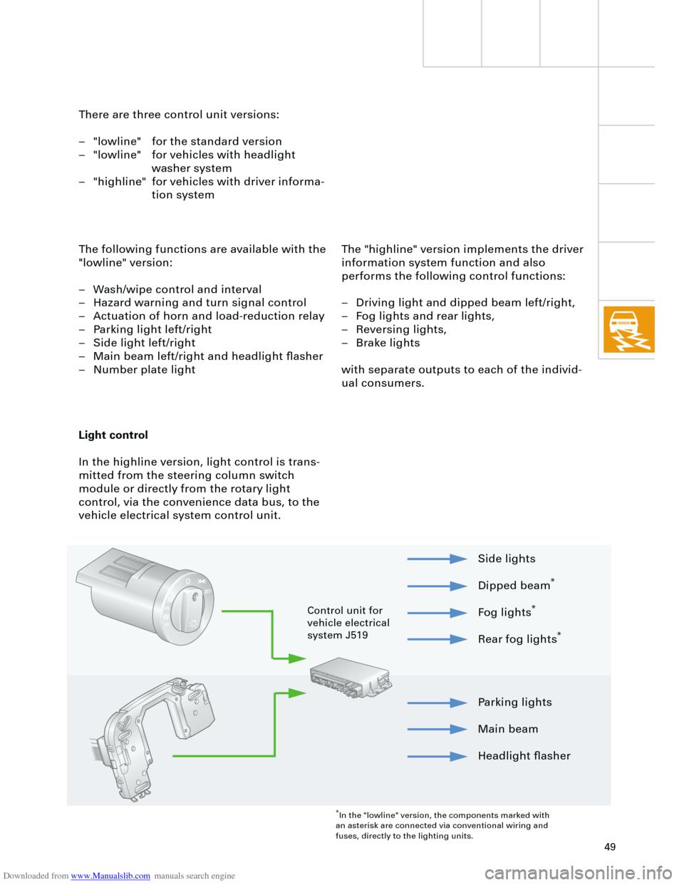
Light control
In the highline version, light control is trans-
mitted from the steering column switch
module or directly from the rotary light
control, via the convenience data bus, to the
vehicle electrical system control unit.
Parking lights
Main beam
Headlight flasher Side lights
Dipped beam
*
Fog lights
*
Rear fog lights
*
*
In the "lowline" version, the components marked with
an asterisk are connected via conventional wiring and
fuses, directly to the lighting units.
Control unit for
vehicle electrical
system J519