2001 AUDI A4 turn signal
[x] Cancel search: turn signalPage 44 of 88
Downloaded from www.Manualslib.com manuals search engine
44
Electrical system
Steering column switch
module
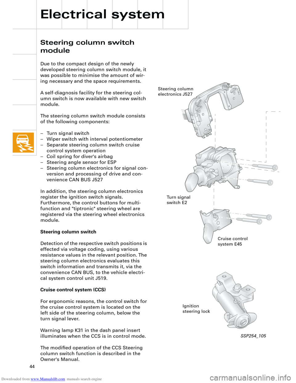
Due to the compact design of the newly
developed steering column switch module, it
was possible to minimise the amount of wir-
ing necessary and the space requirements.
A self-diagnosis facility for the steering col-
umn switch is now available with new switch
module.
The steering column switch module consists
of the following components:
– Turn signal switch
– Wiper switch with interval potentiometer
– Separate steering column switch cruise
control system operation
– Coil spring for diver's airbag
– Steering angle sensor for ESP
– Steering column electronics for signal con-
version and processing of drive and con-
venience CAN BUS J527
In addition, the steering column electronics
register the ignition switch signals.
Furthermore, the control buttons for multi-
function and "tiptronic" steering wheel are
registered via the steering wheel electronics
module.
Steering column switch
Detection of the respective switch positions is
effected via voltage coding, using various
resistance values in the relevant position. The
steering column electronics evaluates this
switch information and transmits it, via the
convenience CAN BUS, to the vehicle electri-
cal system control unit J519.
Cruise control system (CCS)
For ergonomic reasons, the control switch for
the cruise control system is located on the
left side of the steering column, below the
turn signal lever.
Warning lamp K31 in the dash panel insert
illuminates when the CCS is in control mode.
The modified operation of the CCS Steering
column switch function is described in the
Owner's Manual.
Cruise control
system E45
Ignition
steering lock Steering column
electronics J527
Turn signal
switch E2
SSP254_105
Page 46 of 88
Downloaded from www.Manualslib.com manuals search engine
46
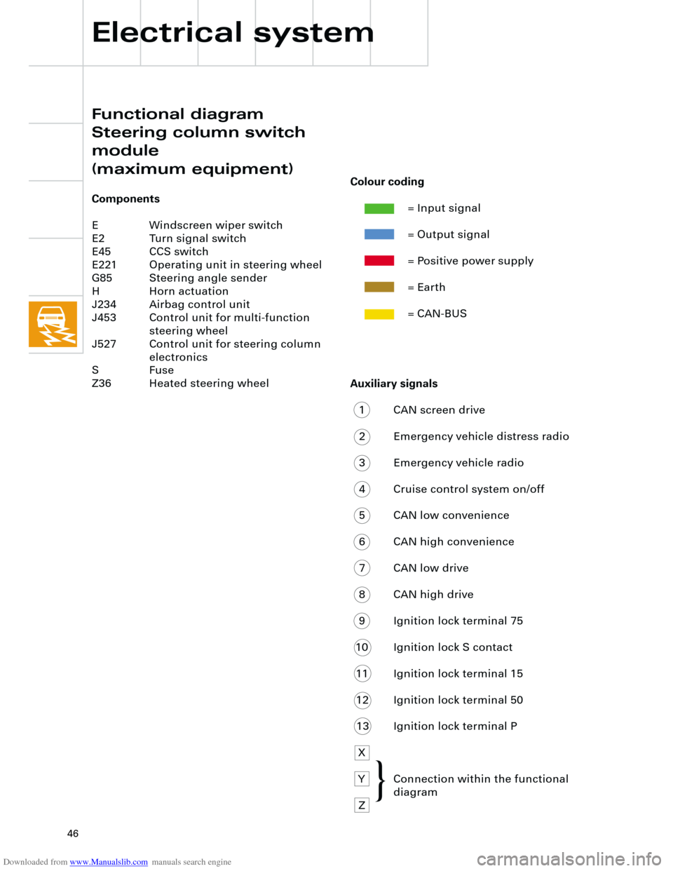
Auxiliary signals
1 CAN screen drive
2 Emergency vehicle distress radio
3 Emergency vehicle radio
4 Cruise control system on/off
5 CAN low convenience
6 CAN high convenience
7 CAN low drive
8 CAN high drive
9 Ignition lock terminal 75
10 Ignition lock S contact
11 Ignition lock terminal 15
12 Ignition lock terminal 50
13 Ignition lock terminal P
X
Y Connection within the functional
diagram
Z
Electrical system
Functional diagram
Steering column switch
module
(maximum equipment)
Components
E Windscreen wiper switch
E2 Turn signal switch
E45 CCS switch
E221 Operating unit in steering wheel
G85 Steering angle sender
H Horn actuation
J234 Airbag control unit
J453 Control unit for multi-function
steering wheel
J527 Control unit for steering column
electronics
S Fuse
Z36 Heated steering wheel
Colour coding
= Input signal
= Output signal
= Positive power supply
= Earth
= CAN-BUS
{
Page 49 of 88
Downloaded from www.Manualslib.com manuals search engine
49
There are three control unit versions:
– "lowline" for the standard version
– "lowline" for vehicles with headlight
washer system
– "highline" for vehicles with driver informa-
tion system
The following functions are available with the
"lowline" version:
– Wash/wipe control and interval
– Hazard warning and turn signal control
– Actuation of horn and load-reduction relay
– Parking light left/right
– Side light left/right
– Main beam left/right and headlight flasher
– Number plate lightThe "highline" version implements the driver
information system function and also
performs the following control functions:
– Driving light and dipped beam left/right,
– Fog lights and rear lights,
– Reversing lights,
– Brake lights
with separate outputs to each of the individ-
ual consumers.
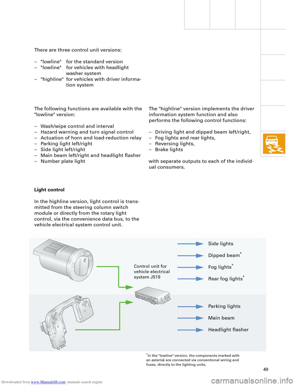
Light control
In the highline version, light control is trans-
mitted from the steering column switch
module or directly from the rotary light
control, via the convenience data bus, to the
vehicle electrical system control unit.
Parking lights
Main beam
Headlight flasher Side lights
Dipped beam
*
Fog lights
*
Rear fog lights
*
*
In the "lowline" version, the components marked with
an asterisk are connected via conventional wiring and
fuses, directly to the lighting units.
Control unit for
vehicle electrical
system J519
Page 50 of 88
Downloaded from www.Manualslib.com manuals search engine
50
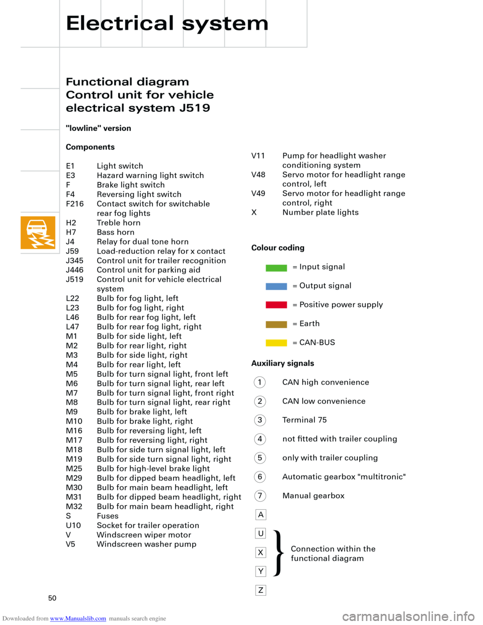
Auxiliary signals
1 CAN high convenience
2 CAN low convenience
3 Terminal 75
4 not fitted with trailer coupling
5 only with trailer coupling
6 Automatic gearbox "multitronic"
7 Manual gearbox
A
U
X
Y
Z
Electrical system
"lowline" version
Components
E1 Light switch
E3 Hazard warning light switch
F Brake light switch
F4 Reversing light switch
F216 Contact switch for switchable
rear fog lights
H2 Treble horn
H7 Bass horn
J4 Relay for dual tone horn
J59 Load-reduction relay for x contact
J345 Control unit for trailer recognition
J446 Control unit for parking aid
J519 Control unit for vehicle electrical
system
L22 Bulb for fog light, left
L23 Bulb for fog light, right
L46 Bulb for rear fog light, left
L47 Bulb for rear fog light, right
M1 Bulb for side light, left
M2 Bulb for rear light, right
M3 Bulb for side light, right
M4 Bulb for rear light, left
M5 Bulb for turn signal light, front left
M6 Bulb for turn signal light, rear left
M7 Bulb for turn signal light, front right
M8 Bulb for turn signal light, rear right
M9 Bulb for brake light, left
M10 Bulb for brake light, right
M16 Bulb for reversing light, left
M17 Bulb for reversing light, right
M18 Bulb for side turn signal light, left
M19 Bulb for side turn signal light, right
M25 Bulb for high-level brake light
M29 Bulb for dipped beam headlight, left
M30 Bulb for main beam headlight, left
M31 Bulb for dipped beam headlight, right
M32 Bulb for main beam headlight, right
S Fuses
U10 Socket for trailer operation
V Windscreen wiper motor
V5 Windscreen washer pump
Colour coding
= Input signal
= Output signal
= Positive power supply
= Earth
= CAN-BUS
V11 Pump for headlight washer
conditioning system
V48 Servo motor for headlight range
control, left
V49 Servo motor for headlight range
control, right
X Number plate lights
Connection within the
functional diagram
Functional diagram
Control unit for vehicle
electrical system J519
{
Page 52 of 88
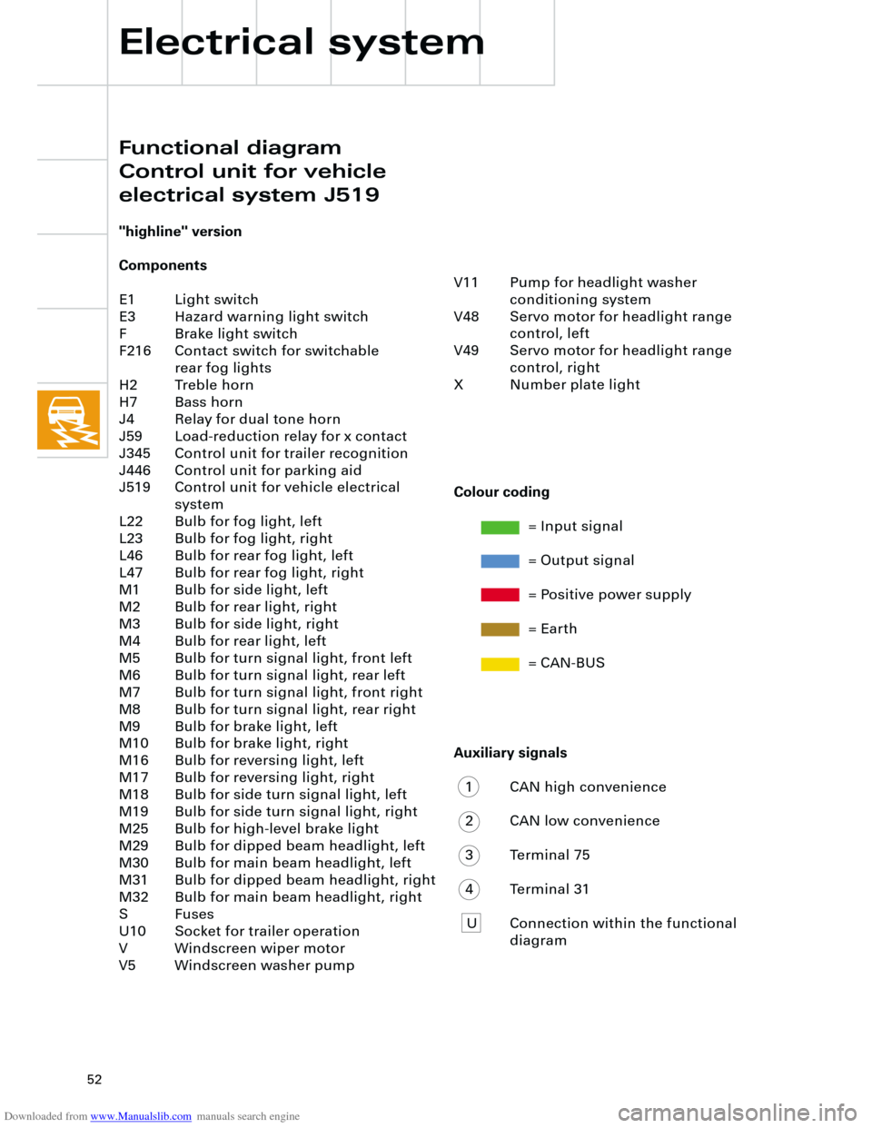
Downloaded from www.Manualslib.com manuals search engine
52
Auxiliary signals
1 CAN high convenience
2 CAN low convenience
3 Terminal 75
4 Terminal 31
U Connection within the functional
diagram V11 Pump for headlight washer
conditioning system
V48 Servo motor for headlight range
control, left
V49 Servo motor for headlight range
control, right
X Number plate light
"highline" version
Components
E1 Light switch
E3 Hazard warning light switch
F Brake light switch
F216 Contact switch for switchable
rear fog lights
H2 Treble horn
H7 Bass horn
J4 Relay for dual tone horn
J59 Load-reduction relay for x contact
J345 Control unit for trailer recognition
J446 Control unit for parking aid
J519 Control unit for vehicle electrical
system
L22 Bulb for fog light, left
L23 Bulb for fog light, right
L46 Bulb for rear fog light, left
L47 Bulb for rear fog light, right
M1 Bulb for side light, left
M2 Bulb for rear light, right
M3 Bulb for side light, right
M4 Bulb for rear light, left
M5 Bulb for turn signal light, front left
M6 Bulb for turn signal light, rear left
M7 Bulb for turn signal light, front right
M8 Bulb for turn signal light, rear right
M9 Bulb for brake light, left
M10 Bulb for brake light, right
M16 Bulb for reversing light, left
M17 Bulb for reversing light, right
M18 Bulb for side turn signal light, left
M19 Bulb for side turn signal light, right
M25 Bulb for high-level brake light
M29 Bulb for dipped beam headlight, left
M30 Bulb for main beam headlight, left
M31 Bulb for dipped beam headlight, right
M32 Bulb for main beam headlight, right
S Fuses
U10 Socket for trailer operation
V Windscreen wiper motor
V5 Windscreen washer pump
Electrical system
Colour coding
= Input signal
= Output signal
= Positive power supply
= Earth
= CAN-BUS
Functional diagram
Control unit for vehicle
electrical system J519
Page 55 of 88
Downloaded from www.Manualslib.com manuals search engine
55
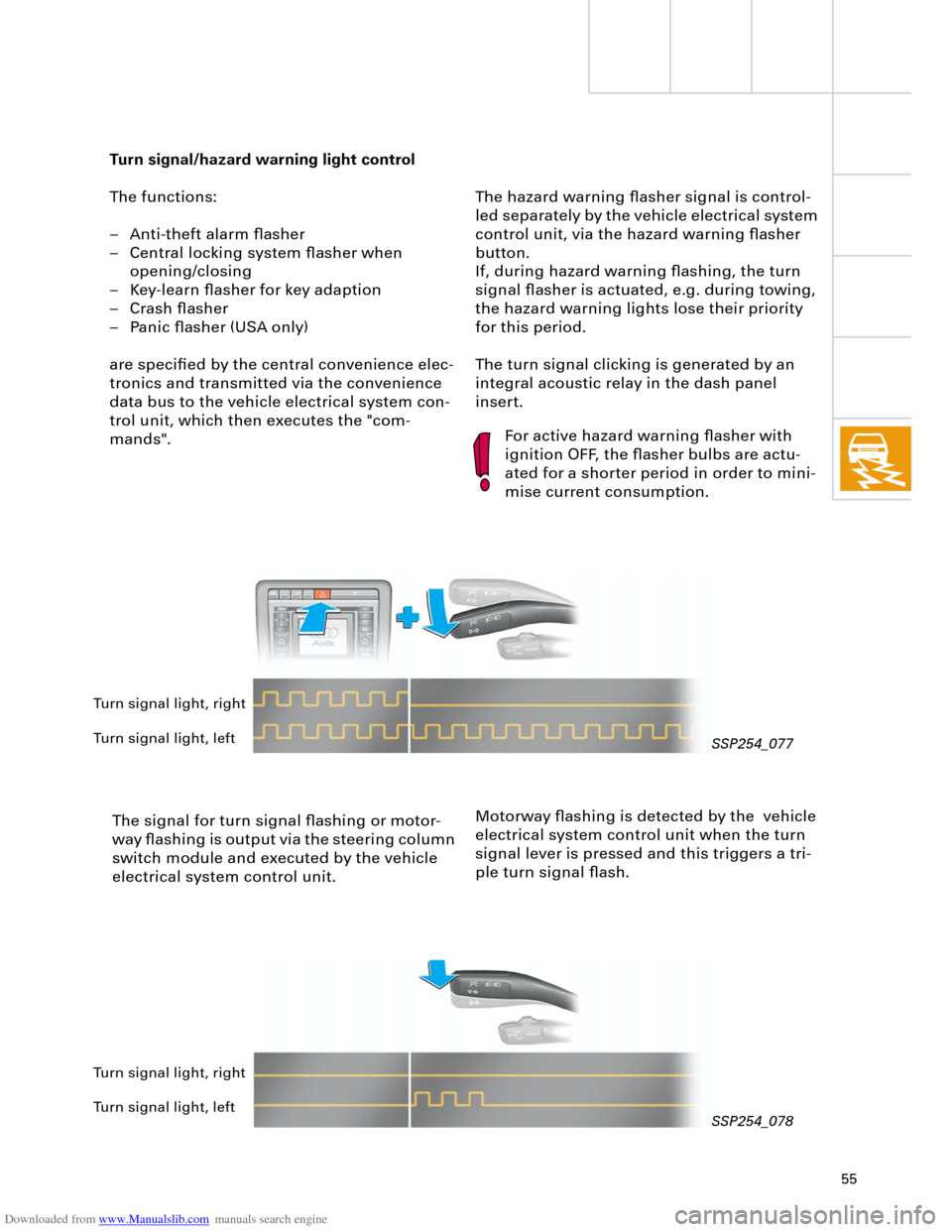
The hazard warning flasher signal is control-
led separately by the vehicle electrical system
control unit, via the hazard warning flasher
button.
If, during hazard warning flashing, the turn
signal flasher is actuated, e.g. during towing,
the hazard warning lights lose their priority
for this period.
The turn signal clicking is generated by an
integral acoustic relay in the dash panel
insert.
Turn signal/hazard warning light control
The functions:
– Anti-theft alarm flasher
– Central locking system flasher when
opening/closing
– Key-learn flasher for key adaption
– Crash flasher
– Panic flasher (USA only)
are specified by the central convenience elec-
tronics and transmitted via the convenience
data bus to the vehicle electrical system con-
trol unit, which then executes the "com-
mands".
The signal for turn signal flashing or motor-
way flashing is output via the steering column
switch module and executed by the vehicle
electrical system control unit.
For active hazard warning flasher with
ignition OFF, the flasher bulbs are actu-
ated for a shorter period in order to mini-
mise current consumption.
Motorway flashing is detected by the vehicle
electrical system control unit when the turn
signal lever is pressed and this triggers a tri-
ple turn signal flash.
Turn signal light, right
Turn signal light, left
Turn signal light, right
Turn signal light, left
SSP254_077
SSP254_078
Page 59 of 88
Downloaded from www.Manualslib.com manuals search engine
59
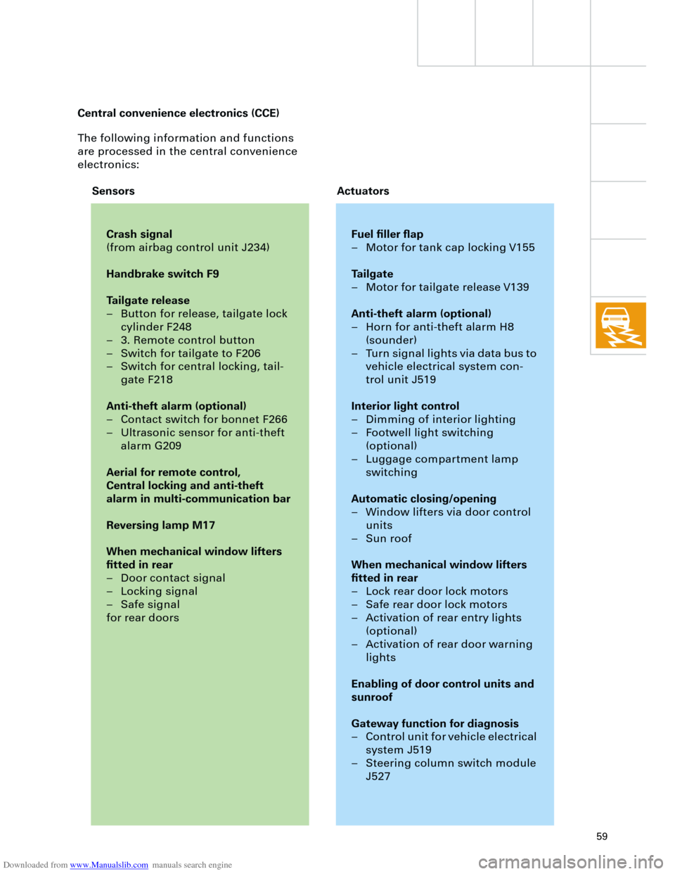
The following information and functions
are processed in the central convenience
electronics:
Crash signal
(from airbag control unit J234)
Handbrake switch F9
Tailgate release
– Button for release, tailgate lock
cylinder F248
– 3. Remote control button
– Switch for tailgate to F206
– Switch for central locking, tail-
gate F218
Anti-theft alarm (optional)
– Contact switch for bonnet F266
– Ultrasonic sensor for anti-theft
alarm G209
Aerial for remote control,
Central locking and anti-theft
alarm in multi-communication bar
Reversing lamp M17
When mechanical window lifters
fitted in rear
– Door contact signal
– Locking signal
– Safe signal
for rear doors
Fuel filler flap
– Motor for tank cap locking V155
Tailgate
– Motor for tailgate release V139
Anti-theft alarm (optional)
– Horn for anti-theft alarm H8
(sounder)
– Turn signal lights via data bus to
vehicle electrical system con-
trol unit J519
Interior light control
– Dimming of interior lighting
– Footwell light switching
(optional)
– Luggage compartment lamp
switching
Automatic closing/opening
– Window lifters via door control
units
– Sun roof
When mechanical window lifters
fitted in rear
– Lock rear door lock motors
– Safe rear door lock motors
– Activation of rear entry lights
(optional)
– Activation of rear door warning
lights
Enabling of door control units and
sunroof
Gateway function for diagnosis
– Control unit for vehicle electrical
system J519
– Steering column switch module
J527
Sensors Actuators Central convenience electronics (CCE)