2001 AUDI A4 cooling
[x] Cancel search: coolingPage 3 of 88

Downloaded from www.Manualslib.com manuals search engine
3
Important:
Note
New
Contents
It is not intended as a workshop manual.
The self-study programme will provide you with information on
design and functions.
For maintenance and repair operations it is essential that you
refer to the current technical literature.
Page
Introduction . . . . . . . . . . . . . . . . . . . . . . . . . . . . . . . . . . . . . . . . . . 4
Body . . . . . . . . . . . . . . . . . . . . . . . . . . . . . . . . . . . . . . . . . . . . . . . . 8
Occupant protection . . . . . . . . . . . . . . . . . . . . . . . . . . . . . . . . 12
Engine and gearbox
Running gear
Axles . . . . . . . . . . . . . . . . . . . . . . . . . . . . . . . . . . . . . . . . . . . . . . . . . . . . . . . . . . . . 26
Mechanical unit mountings . . . . . . . . . . . . . . . . . . . . . . . . . . . . . . . . . . . . . . . . . . . 28
Brake system . . . . . . . . . . . . . . . . . . . . . . . . . . . . . . . . . . . . . . . . . . . . . . . . . . . . . . . 29
Brake assistance . . . . . . . . . . . . . . . . . . . . . . . . . . . . . . . . . . . . . . . . . . . . . . . . . . . . 32
Vehicle electrical system . . . . . . . . . . . . . . . . . . . . . . . . . . . . . . . . . . . . . . . . . . . . . . 36
CAN BUS system . . . . . . . . . . . . . . . . . . . . . . . . . . . . . . . . . . . . . . . . . . . . . . . . . . . . 38
Dash panel insert . . . . . . . . . . . . . . . . . . . . . . . . . . . . . . . . . . . . . . . . . . . . . . . . . . . . 40
Steering column switch module . . . . . . . . . . . . . . . . . . . . . . . . . . . . . . . . . . . . . . . .44
Function circuit diagram . . . . . . . . . . . . . . . . . . . . . . . . . . . . . . . . . . . . . . . 46
Control unit for vehicle electrical system . . . . . . . . . . . . . . . . . . . . . . . . . . . . . . . . 48
Function circuit diagram for "lowline" version . . . . . . . . . . . . . . . . . . . . . 50
Function circuit diagram for "highline" version . . . . . . . . . . . . . . . . . . . . 52
Convenience system . . . . . . . . . . . . . . . . . . . . . . . . . . . . . . . . . . . . . . . . . . . . . . . . . 58
Anti-theft alarm system . . . . . . . . . . . . . . . . . . . . . . . . . . . . . . . . . . . . . . . . . . . . . . . 63
Radio - chorus II, concert II and symphony II . . . . . . . . . . . . . . . . . . . . . . . . . . . . . 65
Navigation IV and Navigation Plus-D . . . . . . . . . . . . . . . . . . . . . . . . . . . . . . . . . . . . 69
Multi-communication bar . . . . . . . . . . . . . . . . . . . . . . . . . . . . . . . . . . . . . . . . . . . . . 72
Electric logbook "Audi Logbook" . . . . . . . . . . . . . . . . . . . . . . . . . . . . . . . . . . . . . . . 74
Heater/AC
Design and function . . . . . . . . . . . . . . . . . . . . . . . . . . . . . . . . . . . . . . . . . . . . . . . . . 76
7-piston compressor . . . . . . . . . . . . . . . . . . . . . . . . . . . . . . . . . . . . . . . . . . . . . . . . . 77
Air conditioner . . . . . . . . . . . . . . . . . . . . . . . . . . . . . . . . . . . . . . . . . . . . . . . . . . . . . . 78
Glove compartment cooling . . . . . . . . . . . . . . . . . . . . . . . . . . . . . . . . . . . . . . . . . . . 79
Solar roof . . . . . . . . . . . . . . . . . . . . . . . . . . . . . . . . . . . . . . . . . . . . . . . . . . . . . . . . . . . 80
Fresh air blower . . . . . . . . . . . . . . . . . . . . . . . . . . . . . . . . . . . . . . . . . . . . . . . . . . . . . 81
Actuators/sensors . . . . . . . . . . . . . . . . . . . . . . . . . . . . . . . . . . . . . . . . . . . . . . . . . . . 82
Functional diagram for fully automatic air conditioner . . . . . . . . . . . . . . 84
Additional heater . . . . . . . . . . . . . . . . . . . . . . . . . . . . . . . . . . . . . . . . . . . . . . . . . . . . 86 2.0 l R4 and 3.0 l V6 engines (see SSP 255) . . . . . . . . . . . . . . . . . . . . . . . . . . . . . . . 18
Innovations - 2.5 l V6 TDI engine. . . . . . . . . . . . . . . . . . . . . . . . . . . . . . . . . . . . . . . . 19
Innovations - automatic gearbox . . . . . . . . . . . . . . . . . . . . . . . . . . . . . . . . . . . . . . . 23
Electrical system
Page 22 of 88

Downloaded from www.Manualslib.com manuals search engine
22
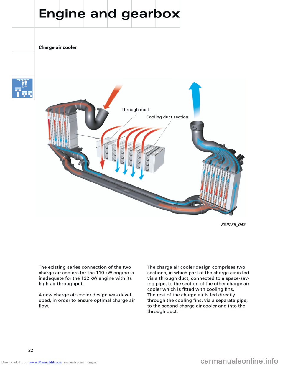
The charge air cooler design comprises two
sections, in which part of the charge air is fed
via a through duct, connected to a space-sav-
ing pipe, to the section of the other charge air
cooler which is fitted with cooling fins.
The rest of the charge air is fed directly
through the cooling fins, via a separate pipe,
to the second charge air cooler and into the
through duct.
Charge air cooler
Engine and gearbox
The existing series connection of the two
charge air coolers for the 110 kW engine is
inadequate for the 132 kW engine with its
high air throughput.
A new charge air cooler design was devel-
oped, in order to ensure optimal charge air
flow.
SSP255_043
Through duct
Cooling duct section
Page 79 of 88

Downloaded from www.Manualslib.com manuals search engine
79
The basic functions of the air conditioner in
the Audi A4 are based on the Audi A6 system
and includes the following features:
– Air-side separation for driver’s and passen-
ger’s side.
– The heat exchanger can be replaced with-
out removing the air conditioner.
– The PTC additional heater element for die-
sel mechanical units can also be replaced
without removing the unit.
– All control motors and potentiometers are
easily accessible and replaceable.
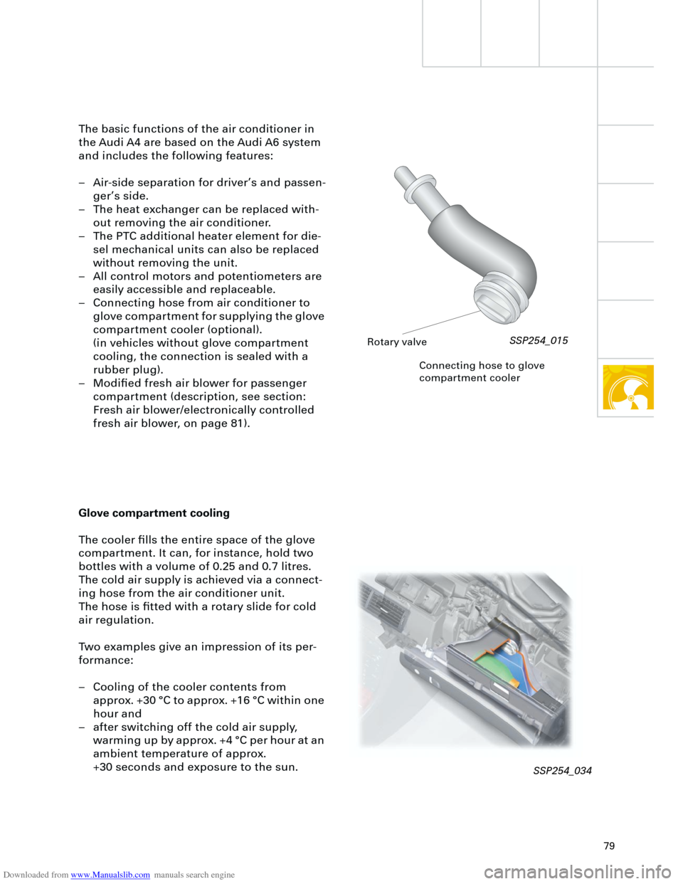
– Connecting hose from air conditioner to
glove compartment for supplying the glove
compartment cooler (optional).
(in vehicles without glove compartment
cooling, the connection is sealed with a
rubber plug).
– Modified fresh air blower for passenger
compartment (description, see section:
Fresh air blower/electronically controlled
fresh air blower, on page 81).
Connecting hose to glove
compartment cooler
Glove compartment cooling
The cooler fills the entire space of the glove
compartment. It can, for instance, hold two
bottles with a volume of 0.25 and 0.7 litres.
The cold air supply is achieved via a connect-
ing hose from the air conditioner unit.
The hose is fitted with a rotary slide for cold
air regulation.
Two examples give an impression of its per-
formance:
– Cooling of the cooler contents from
approx. +30 °C to approx. +16 °C within one
hour and
– after switching off the cold air supply,
warming up by approx. +4 °C per hour at an
ambient temperature of approx.
+30 seconds and exposure to the sun.
Rotary valve
SSP254_015
SSP254_034
Page 86 of 88

Downloaded from www.Manualslib.com manuals search engine
86
+ -
K
Additional heater
Heater/AC
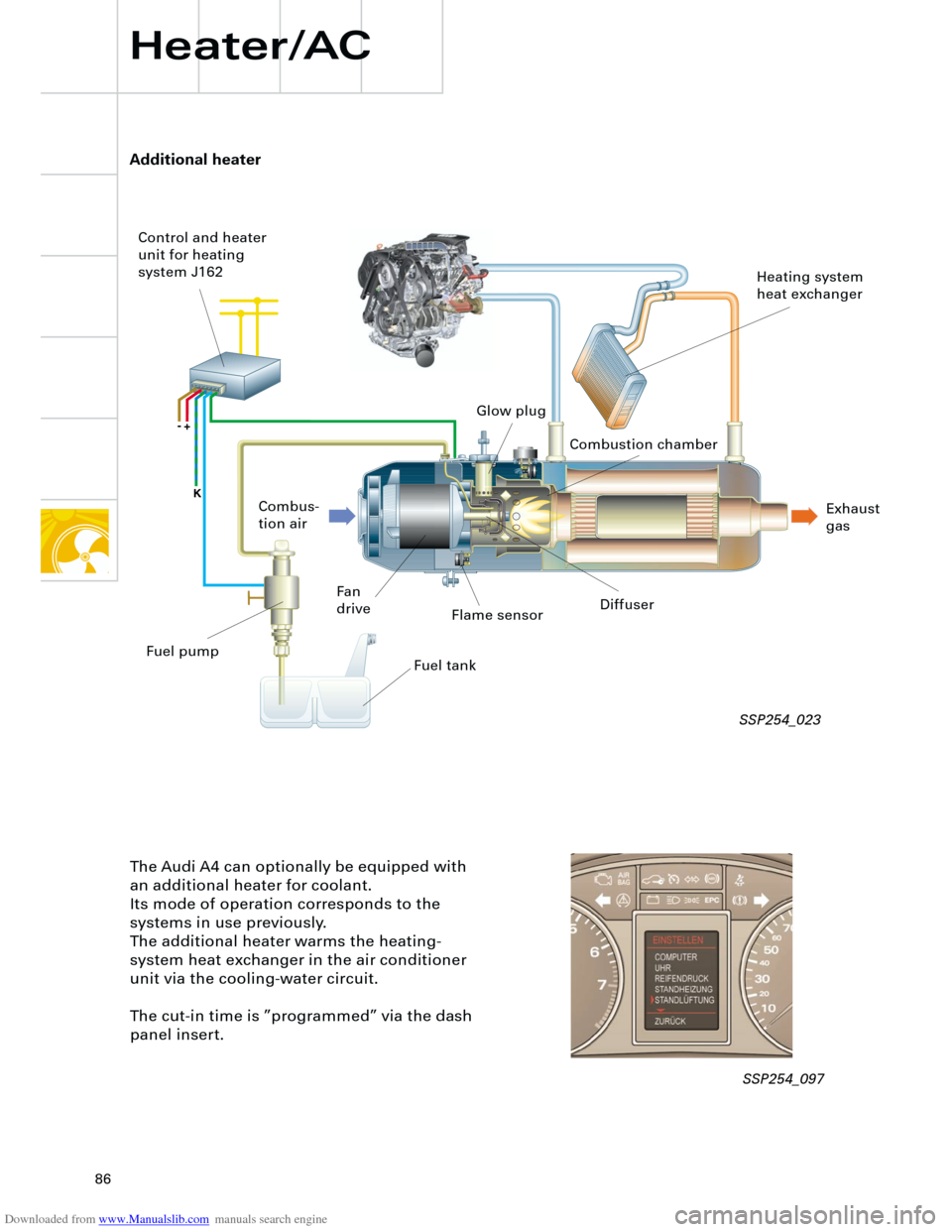
The Audi A4 can optionally be equipped with
an additional heater for coolant.
Its mode of operation corresponds to the
systems in use previously.
The additional heater warms the heating-
system heat exchanger in the air conditioner
unit via the cooling-water circuit.
The cut-in time is ”programmed” via the dash
panel insert.
Flame sensor
Fan
driveDiffuser
Fuel tank Combus-
tion air Control and heater
unit for heating
system J162
Heating system
heat exchanger
Exhaust
gas Combustion chamber Glow plug
Fuel pump
SSP254_023
SSP254_097