2001 AUDI A4 key
[x] Cancel search: keyPage 11 of 88
Downloaded from www.Manualslib.com manuals search engine
11
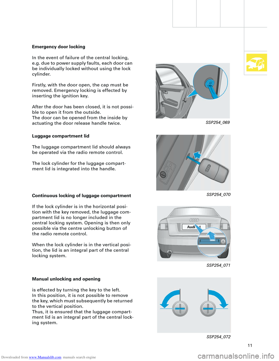
Luggage compartment lid
The luggage compartment lid should always
be operated via the radio remote control.
The lock cylinder for the luggage compart-
ment lid is integrated into the handle.
Emergency door locking
In the event of failure of the central locking,
e.g. due to power supply faults, each door can
be individually locked without using the lock
cylinder.
Firstly, with the door open, the cap must be
removed. Emergency locking is effected by
inserting the ignition key.
After the door has been closed, it is not possi-
ble to open it from the outside.
The door can be opened from the inside by
actuating the door release handle twice.
Continuous locking of luggage compartment
If the lock cylinder is in the horizontal posi-
tion with the key removed, the luggage com-
partment lid is no longer included in the
central locking system. Opening is then only
possible via the centre unlocking button of
the radio remote control.
When the lock cylinder is in the vertical posi-
tion, the lid is an integral part of the central
locking system.
Manual unlocking and opening
is effected by turning the key to the left.
In this position, it is not possible to remove
the key, which must subsequently be returned
to the vertical position.
Thus, it is ensured that the luggage compart-
ment lid is an integral part of the central lock-
ing system.
SSP254_069
SSP254_070
SSP254_071
SSP254_072
Page 13 of 88
Downloaded from www.Manualslib.com manuals search engine
13
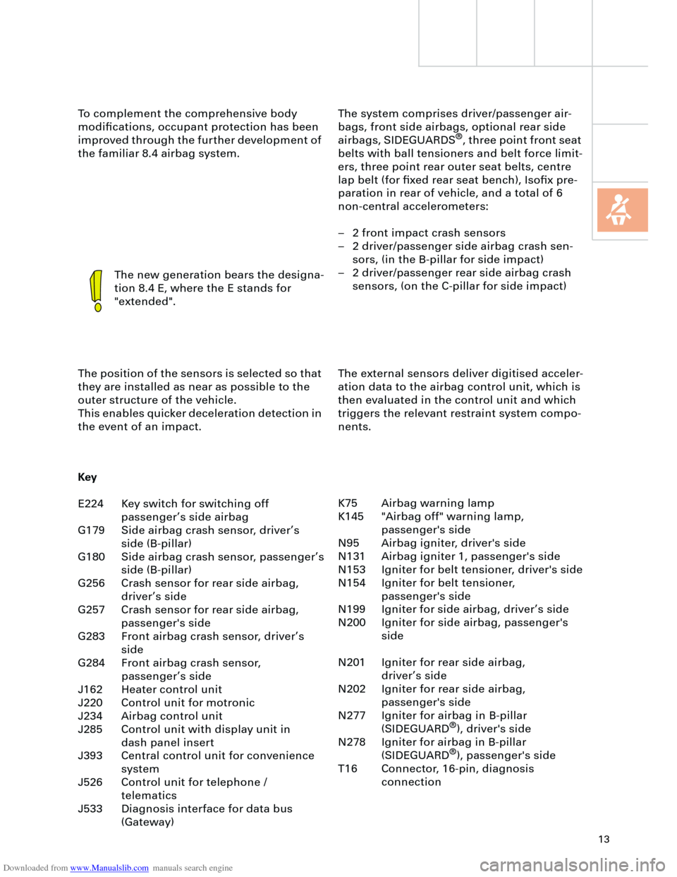
The system comprises driver/passenger air-
bags, front side airbags, optional rear side
airbags, SIDEGUARDS
®
, three point front seat
belts with ball tensioners and belt force limit-
ers, three point rear outer seat belts, centre
lap belt (for fixed rear seat bench), Isofix pre-
paration in rear of vehicle, and a total of 6
non-central accelerometers:
– 2 front impact crash sensors
– 2 driver/passenger side airbag crash sen-
sors, (in the B-pillar for side impact)
– 2 driver/passenger rear side airbag crash
sensors, (on the C-pillar for side impact) To complement the comprehensive body
modifications, occupant protection has been
improved through the further development of
the familiar 8.4 airbag system.
The new generation bears the designa-
tion 8.4 E, where the E stands for
"extended".
The position of the sensors is selected so that
they are installed as near as possible to the
outer structure of the vehicle.
This enables quicker deceleration detection in
the event of an impact.The external sensors deliver digitised acceler-
ation data to the airbag control unit, which is
then evaluated in the control unit and which
triggers the relevant restraint system compo-
nents.
Key
E224 Key switch for switching off
passenger’s side airbag
G179 Side airbag crash sensor, driver’s
side (B-pillar)
G180 Side airbag crash sensor, passenger’s
side (B-pillar)
G256 Crash sensor for rear side airbag,
driver’s side
G257 Crash sensor for rear side airbag,
passenger's side
G283 Front airbag crash sensor, driver’s
side
G284 Front airbag crash sensor,
passenger’s side
J162 Heater control unit
J220 Control unit for motronic
J234 Airbag control unit
J285 Control unit with display unit in
dash panel insert
J393 Central control unit for convenience
system
J526 Control unit for telephone /
telematics
J533 Diagnosis interface for data bus
(Gateway)K75 Airbag warning lamp
K145 "Airbag off" warning lamp,
passenger's side
N95 Airbag igniter, driver's side
N131 Airbag igniter 1, passenger's side
N153 Igniter for belt tensioner, driver's side
N154 Igniter for belt tensioner,
passenger's side
N199 Igniter for side airbag, driver’s side
N200 Igniter for side airbag, passenger's
side
N201 Igniter for rear side airbag,
driver’s side
N202 Igniter for rear side airbag,
passenger's side
N277 Igniter for airbag in B-pillar
(SIDEGUARD
®
), driver's side
N278 Igniter for airbag in B-pillar
(SIDEGUARD
®
), passenger's side
T16 Connector, 16-pin, diagnosis
connection
Page 16 of 88
Downloaded from www.Manualslib.com manuals search engine
16
Occupant protection
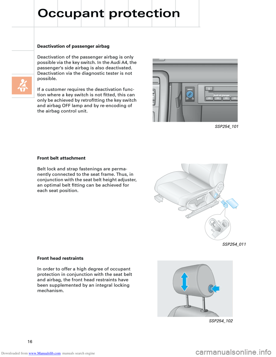
Front belt attachment
Belt lock and strap fastenings are perma-
nently connected to the seat frame. Thus, in
conjunction with the seat belt height adjuster,
an optimal belt fitting can be achieved for
each seat position.
Deactivation of passenger airbag
Deactivation of the passenger airbag is only
possible via the key switch. In the Audi A4, the
passenger's side airbag is also deactivated.
Deactivation via the diagnostic tester is not
possible.
If a customer requires the deactivation func-
tion where a key switch is not fitted, this can
only be achieved by retrofitting the key switch
and airbag OFF lamp and by re-encoding of
the airbag control unit.
Front head restraints
In order to offer a high degree of occupant
protection in conjunction with the seat belt
and airbag, the front head restraints have
been supplemented by an integral locking
mechanism.
aa
aaa
a
SSP254_011
SSP254_102SSP254_101
Page 45 of 88
Downloaded from www.Manualslib.com manuals search engine
45
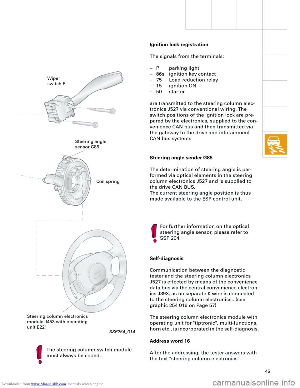
Steering angle sender G85
The determination of steering angle is per-
formed via optical elements in the steering
column electronics J527 and is supplied to
the drive CAN BUS.
The current steering angle position is thus
made available to the ESP control unit.
The steering column switch module
must always be coded.
For further information on the optical
steering angle sensor, please refer to
SSP 204.
Self-diagnosis
Communication between the diagnostic
tester and the steering column electronics
J527 is effected by means of the convenience
data bus via the central convenience electron-
ics J393, as no separate K wire is connected
to the steering column electronics.. (see
graphic 254 018 on Page 57)
The steering column electronics module with
operating unit for "tiptronic", multi-functions,
horn etc., is incorporated in the self-diagnosis.
Address word 16
After the addressing, the tester answers with
the text "steering column electronics".
Wiper
switch E
Steering angle
sensor G85
Steering column electronics
module J453 with operating
unit E221
Ignition lock registration
The signals from the terminals:
– P parking light
– 86s ignition key contact
– 75 Load-reduction relay
– 15 ignition ON
– 50 starter
are transmitted to the steering column elec-
tronics J527 via conventional wiring. The
switch positions of the ignition lock are pre-
pared by the electronics, supplied to the con-
venience CAN bus and then transmitted via
the gateway to the drive and infotainment
CAN bus systems.
Coil spring
RT
SSP254_014
Page 55 of 88
Downloaded from www.Manualslib.com manuals search engine
55
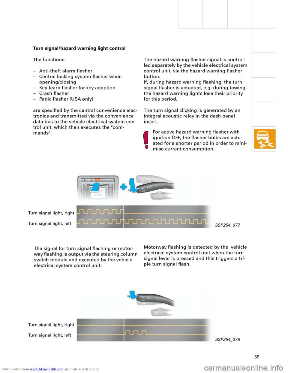
The hazard warning flasher signal is control-
led separately by the vehicle electrical system
control unit, via the hazard warning flasher
button.
If, during hazard warning flashing, the turn
signal flasher is actuated, e.g. during towing,
the hazard warning lights lose their priority
for this period.
The turn signal clicking is generated by an
integral acoustic relay in the dash panel
insert.
Turn signal/hazard warning light control
The functions:
– Anti-theft alarm flasher
– Central locking system flasher when
opening/closing
– Key-learn flasher for key adaption
– Crash flasher
– Panic flasher (USA only)
are specified by the central convenience elec-
tronics and transmitted via the convenience
data bus to the vehicle electrical system con-
trol unit, which then executes the "com-
mands".
The signal for turn signal flashing or motor-
way flashing is output via the steering column
switch module and executed by the vehicle
electrical system control unit.
For active hazard warning flasher with
ignition OFF, the flasher bulbs are actu-
ated for a shorter period in order to mini-
mise current consumption.
Motorway flashing is detected by the vehicle
electrical system control unit when the turn
signal lever is pressed and this triggers a tri-
ple turn signal flash.
Turn signal light, right
Turn signal light, left
Turn signal light, right
Turn signal light, left
SSP254_077
SSP254_078
Page 62 of 88
Downloaded from www.Manualslib.com manuals search engine
62
TS
Electrical system
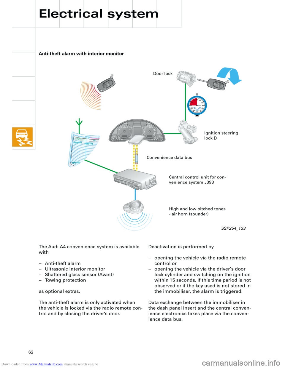
The Audi A4 convenience system is available
with
– Anti-theft alarm
– Ultrasonic interior monitor
– Shattered glass sensor (Avant)
– Towing protection
as optional extras.
The anti-theft alarm is only activated when
the vehicle is locked via the radio remote con-
trol and by closing the driver's door.Deactivation is performed by
– opening the vehicle via the radio remote
control or
– opening the vehicle via the driver’s door
lock cylinder and switching on the ignition
within 15 seconds. If this time period is not
observed or if the key used is not stored in
the immobiliser, the alarm is triggered.
Data exchange between the immobiliser in
the dash panel insert and the central conven-
ience electronics takes place via the conven-
ience data bus.
Anti-theft alarm with interior monitor
High and low pitched tones
- air horn (sounder) Central control unit for con-
venience system J393Ignition steering
lock D Door lock
Convenience data bus
SSP254_133
Page 67 of 88
Downloaded from www.Manualslib.com manuals search engine
67
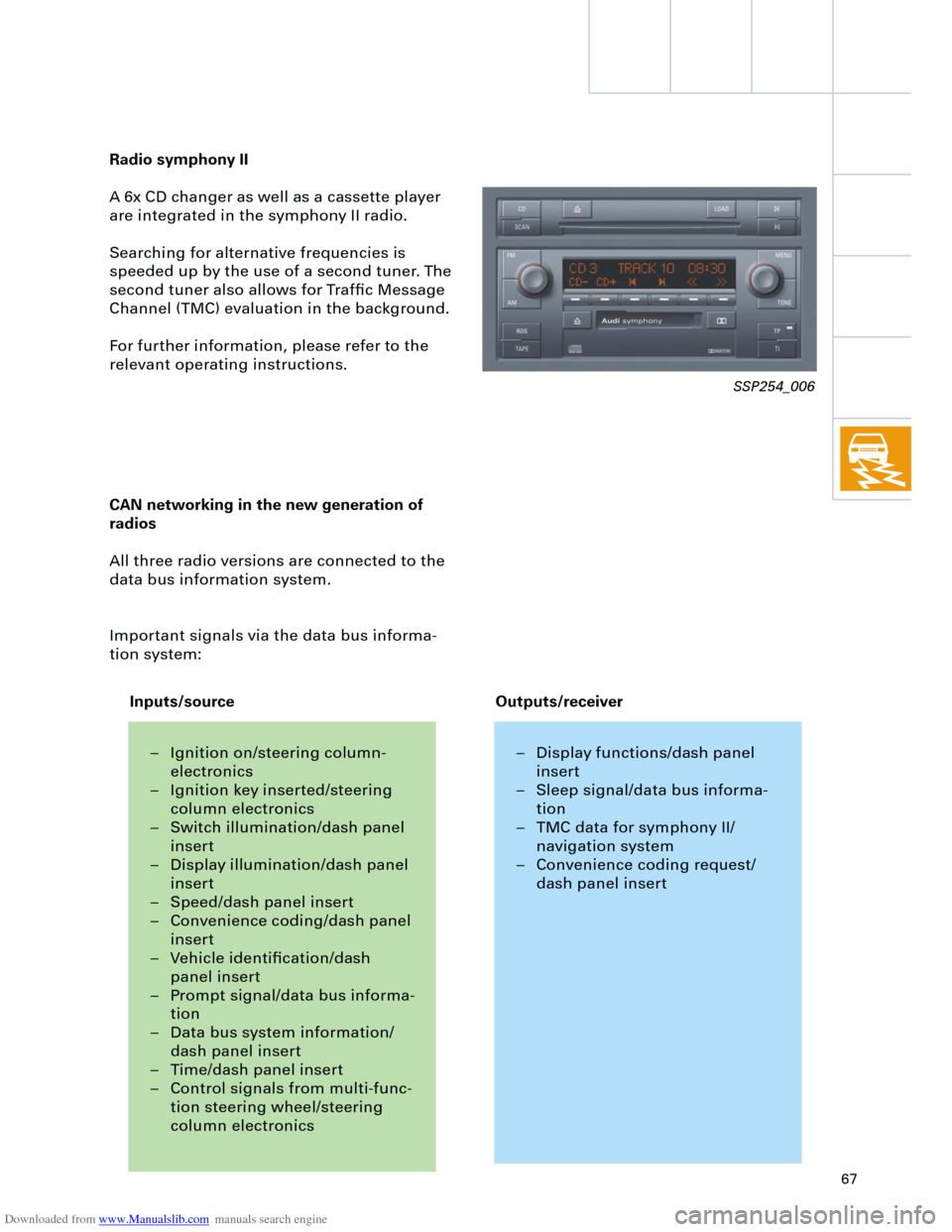
Radio symphony II
A 6x CD changer as well as a cassette player
are integrated in the symphony II radio.
Searching for alternative frequencies is
speeded up by the use of a second tuner. The
second tuner also allows for Traffic Message
Channel (TMC) evaluation in the background.
For further information, please refer to the
relevant operating instructions.
CAN networking in the new generation of
radios
All three radio versions are connected to the
data bus information system.
Important signals via the data bus informa-
tion system:
SSP254_006
– Ignition on/steering column-
electronics
– Ignition key inserted/steering
column electronics
– Switch illumination/dash panel
insert
– Display illumination/dash panel
insert
– Speed/dash panel insert
– Convenience coding/dash panel
insert
– Vehicle identification/dash
panel insert
– Prompt signal/data bus informa-
tion
– Data bus system information/
dash panel insert
– Time/dash panel insert
– Control signals from multi-func-
tion steering wheel/steering
column electronics– Display functions/dash panel
insert
– Sleep signal/data bus informa-
tion
– TMC data for symphony II/
navigation system
– Convenience coding request/
dash panel insert
Inputs/sourceOutputs/receiver
Page 68 of 88
Downloaded from www.Manualslib.com manuals search engine
68
Example:
If the radio is switched on with the ignition
key (S-contact) this requires the exchange of
data between three control units:
– Steering column electronics,
– dash panel insert (gateway) and
– radio.
If the radio does not switch on,
– the signal input in the steering column
electronics (terminal 86S),
– communication between the steering col-
umn electronics and the dash panel
(convenience data bus) and
– communication between the dash panel
and the radio
(data bus information system)
must be checked.
Diagnostics
For diagnosis of radio systems concert II and
symphony II, current consumption of aerial
diversity is monitored via the intermittent
frequency (IF) wiring.
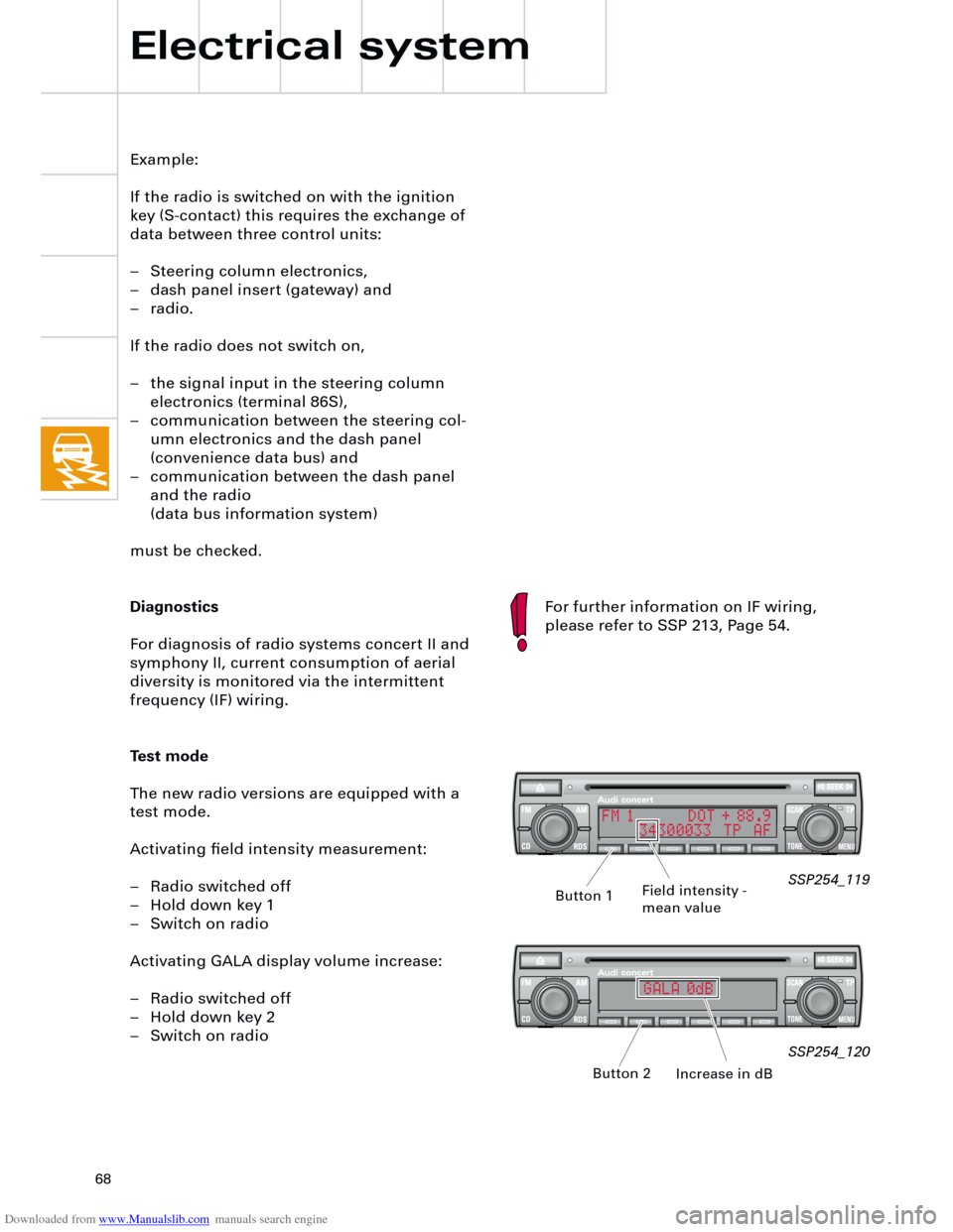
Test mode
The new radio versions are equipped with a
test mode.
Activating field intensity measurement:
– Radio switched off
– Hold down key 1
– Switch on radio
Activating GALA display volume increase:
– Radio switched off
– Hold down key 2
– Switch on radio
Electrical system
SSP254_119
SSP254_120
Field intensity -
mean value
Increase in dB Button 1
Button 2
For further information on IF wiring,
please refer to SSP 213, Page 54.
FM 1 DOT + 88.9
34300033 TP AF
GALA 0dB