Page 64 of 88

Downloaded from www.Manualslib.com manuals search engine
64
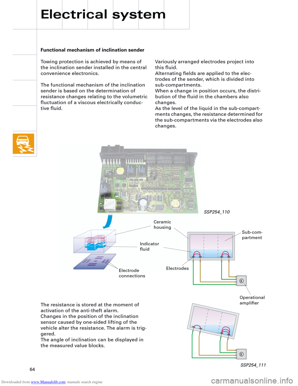
Functional mechanism of inclination sender
Towing protection is achieved by means of
the inclination sender installed in the central
convenience electronics.
The functional mechanism of the inclination
sender is based on the determination of
resistance changes relating to the volumetric
fluctuation of a viscous electrically conduc-
tive fluid.
Electrical system
SSP254_110
The resistance is stored at the moment of
activation of the anti-theft alarm.
Changes in the position of the inclination
sensor caused by one-sided lifting of the
vehicle alter the resistance. The alarm is trig-
gered.
The angle of inclination can be displayed in
the measured value blocks.
Sub-com-
partment
Ceramic
housing
Indicator
fluid
Electrodes
Operational
amplifier
Variously arranged electrodes project into
this fluid.
Alternating fields are applied to the elec-
trodes of the sender, which is divided into
sub-compartments.
When a change in position occurs, the distri-
bution of the fluid in the chambers also
changes.
As the level of the liquid in the sub-compart-
ments changes, the resistance determined for
the sub-compartments via the electrodes also
changes.
Electrode
connections
SSP254_111
Page 76 of 88

Downloaded from www.Manualslib.com manuals search engine
76
Heater/AC
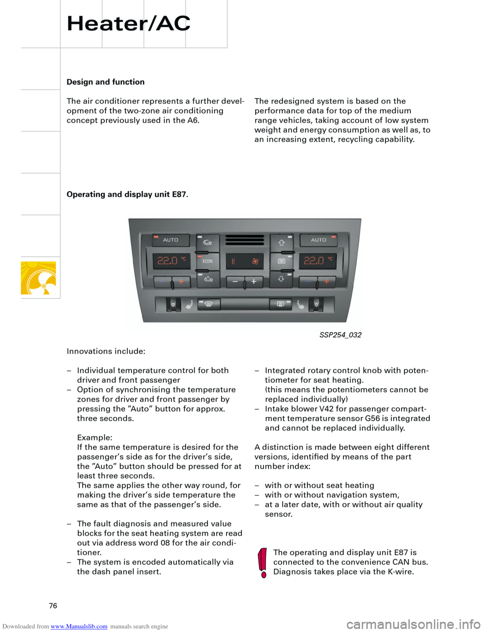
Operating and display unit E87.
The redesigned system is based on the
performance data for top of the medium
range vehicles, taking account of low system
weight and energy consumption as well as, to
an increasing extent, recycling capability.
The operating and display unit E87 is
connected to the convenience CAN bus.
Diagnosis takes place via the K-wire.
Design and function
The air conditioner represents a further devel-
opment of the two-zone air conditioning
concept previously used in the A6.
Innovations include:
– Individual temperature control for both
driver and front passenger
– Option of synchronising the temperature
zones for driver and front passenger by
pressing the ”Auto” button for approx.
three seconds.
Example:
If the same temperature is desired for the
passenger’s side as for the driver’s side,
the ”Auto” button should be pressed for at
least three seconds.
The same applies the other way round, for
making the driver’s side temperature the
same as that of the passenger’s side.
– The fault diagnosis and measured value
blocks for the seat heating system are read
out via address word 08 for the air condi-
tioner.
– The system is encoded automatically via
the dash panel insert.– Integrated rotary control knob with poten-
tiometer for seat heating.
(this means the potentiometers cannot be
replaced individually)
– Intake blower V42 for passenger compart-
ment temperature sensor G56 is integrated
and cannot be replaced individually.
A distinction is made between eight different
versions, identified by means of the part
number index:
– with or without seat heating
– with or without navigation system,
– at a later date, with or without air quality
sensor.
SSP254_032
Page 78 of 88
Downloaded from www.Manualslib.com manuals search engine
78
Air conditioner
Heater/AC
Defrost
flaps
Flaps for
centre ventDefrost flap control
motor V107
Temperature
flap (upper)
Left temperature
flap control
motor V158Right tempera-
ture flap control
motor V159
Temperature
flap (lower)
Flaps for footwell
ventFootwell vent tempera-
ture sender (left) G261Footwell vent tempera-
ture sender (right) G262
Sender for outlet
temperature,
evaporator G263 Central flap
control motor V70
Temperature
sensor - fresh air
intake channel G89
Fresh air/air-
flow flap
Air recirculation
flap control
motor V113
Motor for air flow
flap V71
Recircula-
ted-air flap
Vent temperature
sender
left right
G150 G151
SSP254_019
Page 82 of 88
Downloaded from www.Manualslib.com manuals search engine
82
Actuators/sensors
Heater/AC
Ambient temperature sensor
G17
Dash panel temperature
sensor G56
and
Temperature selection in the air condi-
tioner operating and display unit E87
Sender for footwell vent temperature,
right, G262
Sender for footwell vent tempera-
ture, left, G261
High-pressure sender G65 Evaporator outlet temperature
sender G263 Fresh air intake temperature
sensor G89
Sunlight penetration photo-
sensor G107
Signals:
Terminal 31b from automatic wash/wipe interval system
Regulating valve for air conditioner compressor N280
Air quality sensor G238 Vent temperature sender, right, G151
Vent temperature sender, left, G150
E
C
O
NO
F
F
Page 84 of 88

Downloaded from www.Manualslib.com manuals search engine
84
Heater/AC
Functional diagram
for fully automatic air
conditioner
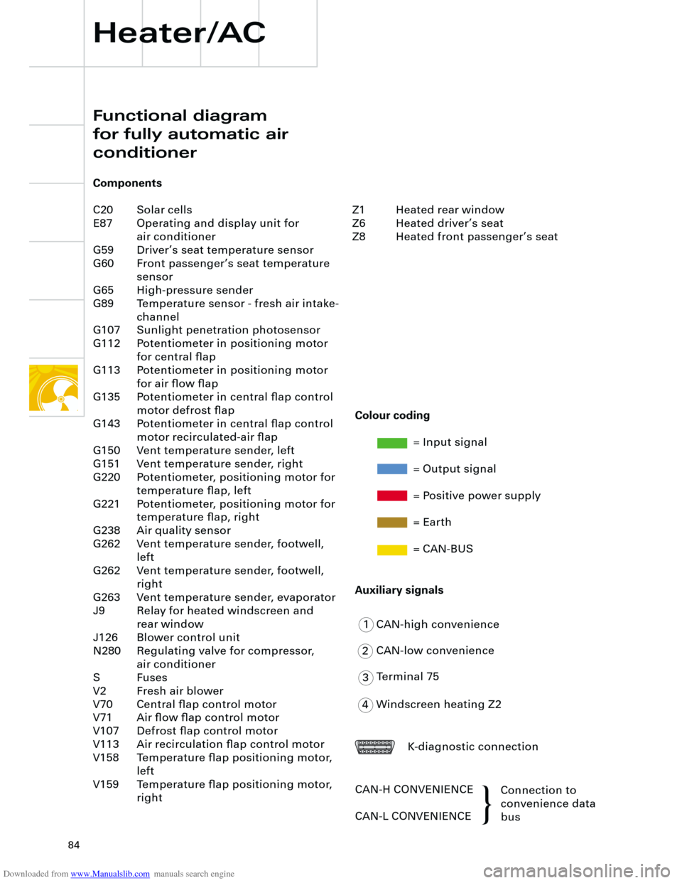
Components
C20 Solar cells
E87 Operating and display unit for
air conditioner
G59 Driver’s seat temperature sensor
G60 Front passenger’s seat temperature
sensor
G65 High-pressure sender
G89 Temperature sensor - fresh air intake-
channel
G107 Sunlight penetration photosensor
G112 Potentiometer in positioning motor
for central flap
G113 Potentiometer in positioning motor
for air flow flap
G135 Potentiometer in central flap control
motor defrost flap
G143 Potentiometer in central flap control
motor recirculated-air flap
G150 Vent temperature sender, left
G151 Vent temperature sender, right
G220 Potentiometer, positioning motor for
temperature flap, left
G221 Potentiometer, positioning motor for
temperature flap, right
G238 Air quality sensor
G262 Vent temperature sender, footwell,
left
G262 Vent temperature sender, footwell,
right
G263 Vent temperature sender, evaporator
J9 Relay for heated windscreen and
rear window
J126 Blower control unit
N280 Regulating valve for compressor,
air conditioner
S Fuses
V2 Fresh air blower
V70 Central flap control motor
V71 Air flow flap control motor
V107 Defrost flap control motor
V113 Air recirculation flap control motor
V158 Temperature flap positioning motor,
left
V159 Temperature flap positioning motor,
right
1
2
3
4CAN-high convenience
CAN-low convenience
Terminal 75
Windscreen heating Z2
K-diagnostic connection
CAN-H CONVENIENCE
CAN-L CONVENIENCEConnection to
convenience data
bus
Colour coding
= Input signal
= Output signal
= Positive power supply
= Earth
= CAN-BUS
Auxiliary signals
Z1 Heated rear window
Z6 Heated driver’s seat
Z8 Heated front passenger’s seat
{
Page 86 of 88
Downloaded from www.Manualslib.com manuals search engine
86
+ -
K
Additional heater
Heater/AC
The Audi A4 can optionally be equipped with
an additional heater for coolant.
Its mode of operation corresponds to the
systems in use previously.
The additional heater warms the heating-
system heat exchanger in the air conditioner
unit via the cooling-water circuit.
The cut-in time is ”programmed” via the dash
panel insert.
Flame sensor
Fan
driveDiffuser
Fuel tank Combus-
tion air Control and heater
unit for heating
system J162
Heating system
heat exchanger
Exhaust
gas Combustion chamber Glow plug
Fuel pump
SSP254_023
SSP254_097
Page:
< prev 1-8 9-16 17-24