Page 17 of 88
Downloaded from www.Manualslib.com manuals search engine
17
Crash signal processing
There are two separate crash signal outputs:
One crash signal is output via the conven-
tional wiring and triggers the following func-
tions:
– Transmitting an emergency call via the
control unit for telephone/telematics J526
(optional)
– unlocking the vehicle,
– Switch on interior light
(switch must be set to door contact),
– switching on hazard warning lights via the
central convenience electronics J393.
The auxiliary heater J162 (optional) is
switched off by the central convenience
electronics J393 via a CAN convenience
message.
The second crash signal output functions via
the convenience CAN bus, which switches off
the engine fuel supply via the engine control
unit J220.
Page 18 of 88
Downloaded from www.Manualslib.com manuals search engine
18
Engine and gearbox
with five-valve cylinder head, produces162 kW
(220 PS) at 6300 rpm from 2976 cm
3
.
The maximum torque of 300 Nm is developed
at 3200 rpm.
Engine
The 4-cylinder, 2.0 l engine
provides high propulsive force due to the
maximum torque of 195 Nm at 3300 rpm.
The 3,0 l V6 engine
Detailed information on these engines
can be found in SSP 255.
Power output [kW] Torque [Nm]
Power output [kW]Torque [Nm]
SSP254_060
SSP254_061
Engine speed in rpm
Engine speed in rpm
SSP254_038
SSP254_030
Page 19 of 88
Downloaded from www.Manualslib.com manuals search engine
19
The injection system was modified in order to
reduce exhaust gas and particle emissions. The main features of the basic engine are the
same as those of the familiar V6 TDI engine
with 132 kW (180 PS).
Power output and torque curve values could
be maintained under conditions which were
well within EU 3 limit values.
NOx
HC+NOxCO
Particle
Limit value [%]
EU 3 limit values 100 %
Particle = 0.05 g/km
CO = 0.64 g/km
HC+NOx = 0.56 g/km
NOx = 0.50 g/km
SSP255_038
Innovations 2.5 l V6 TDI engine
Capacity: 2496 cm
3
Bore: 78.3 mm
Stroke: 86.4 mm
Compression: 18.5 : 1
Power output: 132 kW (180 PS)
Torque: 370 Nm at 1500 rpm
SSP255_039
Power output [kW]Torque [Nm]
Technical data
Injection system: Bosch VE VP 44 S3.5
Turbocharger: VNT 20
Exhaust emissions class: EU 3
Consumption: urban 11.0 l/100 km
(6-gear, quattro) country 6.1 l/100 km
average 7.8 l/100 km
Engine speed in rpm
SSP255_045
Page 20 of 88

Downloaded from www.Manualslib.com manuals search engine
20
Engine and gearbox
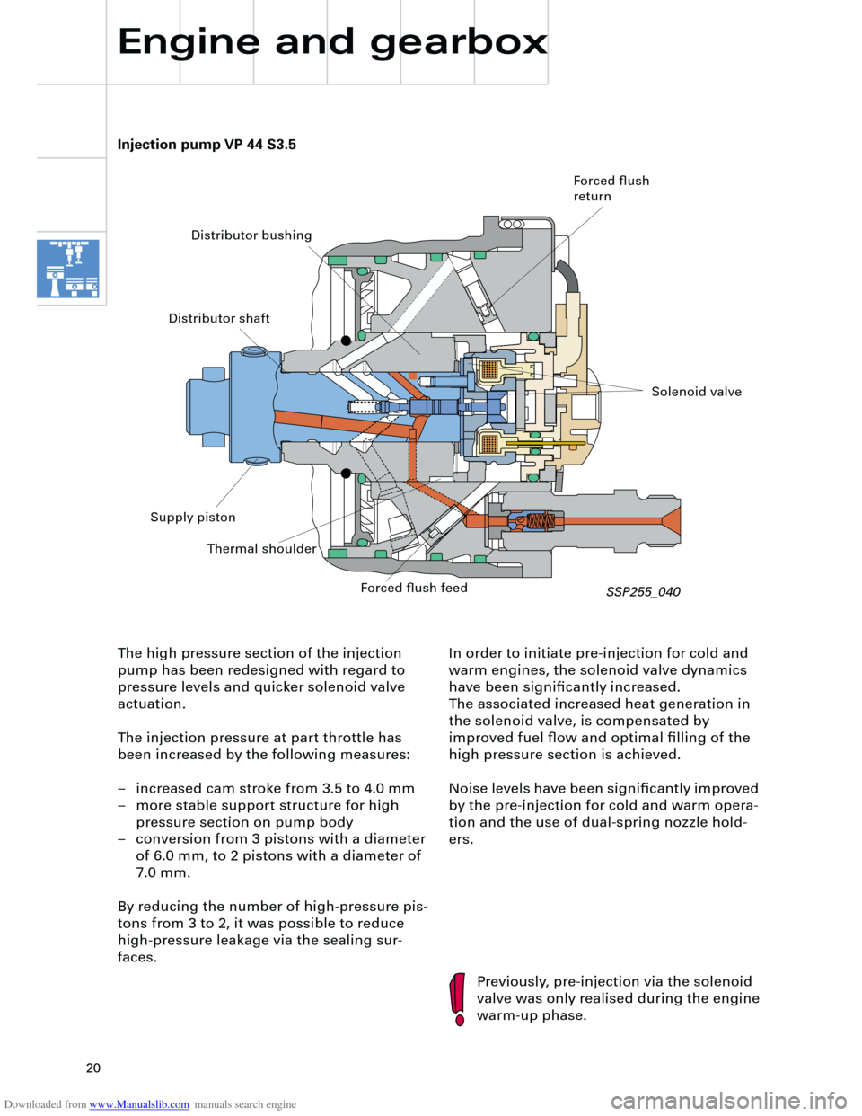
In order to initiate pre-injection for cold and
warm engines, the solenoid valve dynamics
have been significantly increased.
The associated increased heat generation in
the solenoid valve, is compensated by
improved fuel flow and optimal filling of the
high pressure section is achieved.
Noise levels have been significantly improved
by the pre-injection for cold and warm opera-
tion and the use of dual-spring nozzle hold-
ers.
Injection pump VP 44 S3.5
Previously, pre-injection via the solenoid
valve was only realised during the engine
warm-up phase. The high pressure section of the injection
pump has been redesigned with regard to
pressure levels and quicker solenoid valve
actuation.
The injection pressure at part throttle has
been increased by the following measures:
– increased cam stroke from 3.5 to 4.0 mm
– more stable support structure for high
pressure section on pump body
– conversion from 3 pistons with a diameter
of 6.0 mm, to 2 pistons with a diameter of
7.0 mm.
By reducing the number of high-pressure pis-
tons from 3 to 2, it was possible to reduce
high-pressure leakage via the sealing sur-
faces.
Forced flush
return
Distributor bushing
Distributor shaft
Supply piston
Thermal shoulder
Forced flush feed
Solenoid valve
SSP255_040
Page 21 of 88
Downloaded from www.Manualslib.com manuals search engine
21
Injector
For the first time, an ICU injector (
I
nverse
C
av-
ity
U
ndercut) is used, which has a dual needle
guide.
The advantage of this ICU geometry is a sig-
nificantly improved spray formation, espe-
cially in the part throttle range for small
injection quantities and short needle lift.
SSP255_042
ICU seat geometry
Dual needle guide
Due to the improved spray formation through
the use of the ICU injector, it was possible to
reduce the exhaust emissions and the particle
values by up to 20 %.
ICU seat geometry Standard seat geometry
SSP255_041
Page 22 of 88
Downloaded from www.Manualslib.com manuals search engine
22
The charge air cooler design comprises two
sections, in which part of the charge air is fed
via a through duct, connected to a space-sav-
ing pipe, to the section of the other charge air
cooler which is fitted with cooling fins.
The rest of the charge air is fed directly
through the cooling fins, via a separate pipe,
to the second charge air cooler and into the
through duct.
Charge air cooler
Engine and gearbox
The existing series connection of the two
charge air coolers for the 110 kW engine is
inadequate for the 132 kW engine with its
high air throughput.
A new charge air cooler design was devel-
oped, in order to ensure optimal charge air
flow.
SSP255_043
Through duct
Cooling duct section
Page 23 of 88

Downloaded from www.Manualslib.com manuals search engine
23
P
R+NDS
Innovations - automatic
gearbox
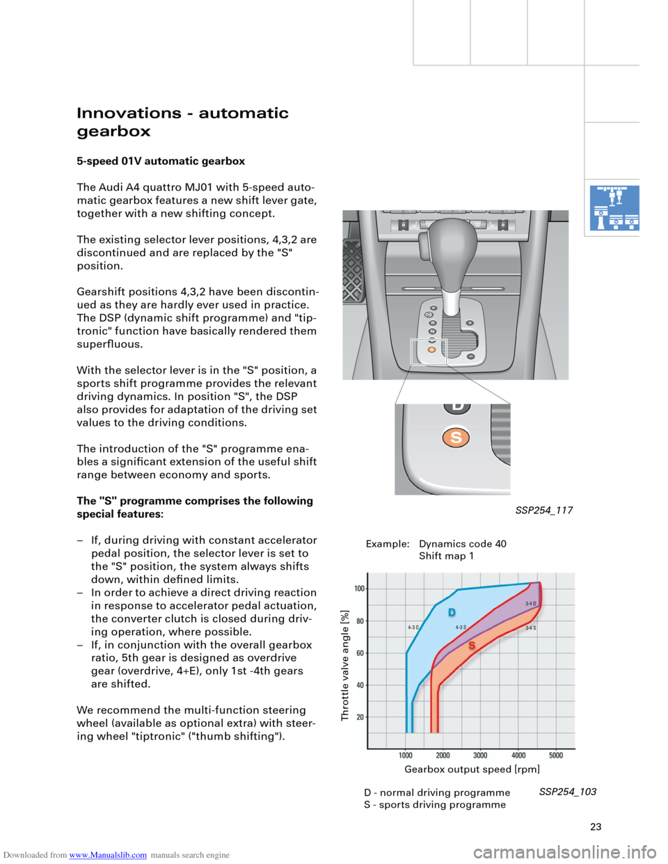
5-speed 01V automatic gearbox
The Audi A4 quattro MJ01 with 5-speed auto-
matic gearbox features a new shift lever gate,
together with a new shifting concept.
The existing selector lever positions, 4,3,2 are
discontinued and are replaced by the "S"
position.
Gearshift positions 4,3,2 have been discontin-
ued as they are hardly ever used in practice.
The DSP (dynamic shift programme) and "tip-
tronic" function have basically rendered them
superfluous.
With the selector lever is in the "S" position, a
sports shift programme provides the relevant
driving dynamics. In position "S", the DSP
also provides for adaptation of the driving set
values to the driving conditions.
The introduction of the "S" programme ena-
bles a significant extension of the useful shift
range between economy and sports.
The "S" programme comprises the following
special features:
– If, during driving with constant accelerator
pedal position, the selector lever is set to
the "S" position, the system always shifts
down, within defined limits.
– In order to achieve a direct driving reaction
in response to accelerator pedal actuation,
the converter clutch is closed during driv-
ing operation, where possible.
– If, in conjunction with the overall gearbox
ratio, 5th gear is designed as overdrive
gear (overdrive, 4+E), only 1st -4th gears
are shifted.
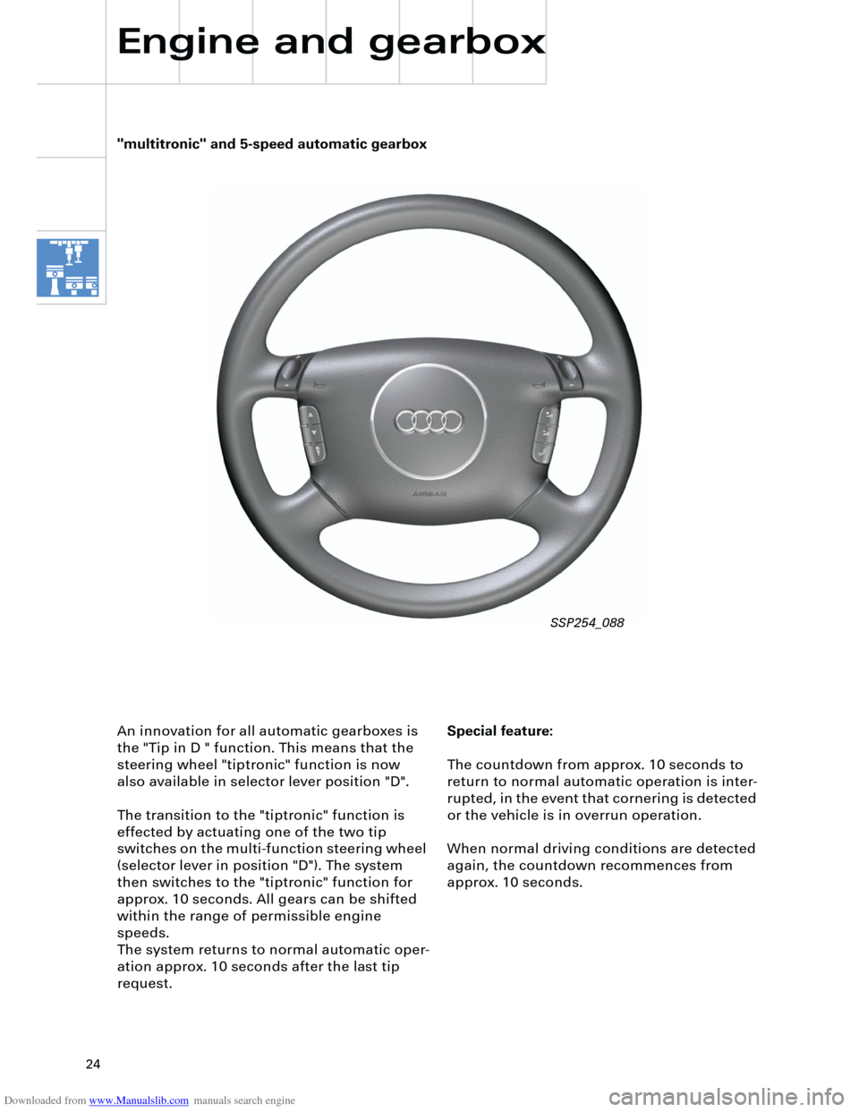
We recommend the multi-function steering
wheel (available as optional extra) with steer-
ing wheel "tiptronic" ("thumb shifting").
Gearbox output speed [rpm]
Throttle valve angle [%]
SSP254_103 SSP254_117
D - normal driving programme
S - sports driving programmeExample: Dynamics code 40
Shift map 1
Page 24 of 88

Downloaded from www.Manualslib.com manuals search engine
24
Special feature:
The countdown from approx. 10 seconds to
return to normal automatic operation is inter-
rupted, in the event that cornering is detected
or the vehicle is in overrun operation.
When normal driving conditions are detected
again, the countdown recommences from
approx. 10 seconds. An innovation for all automatic gearboxes is
the "Tip in D " function. This means that the
steering wheel "tiptronic" function is now
also available in selector lever position "D".
The transition to the "tiptronic" function is
effected by actuating one of the two tip
switches on the multi-function steering wheel
(selector lever in position "D"). The system
then switches to the "tiptronic" function for
approx. 10 seconds. All gears can be shifted
within the range of permissible engine
speeds.
The system returns to normal automatic oper-
ation approx. 10 seconds after the last tip
request.
Engine and gearbox
"multitronic" and 5-speed automatic gearbox
SSP254_088