Page 33 of 88

Downloaded from www.Manualslib.com manuals search engine
33
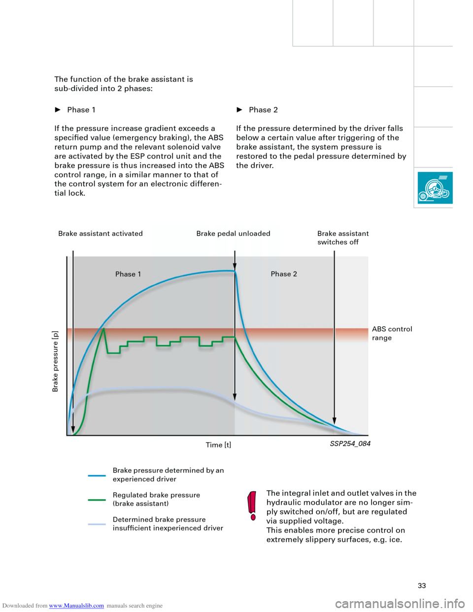
• Phase 2
If the pressure determined by the driver falls
below a certain value after triggering of the
brake assistant, the system pressure is
restored to the pedal pressure determined by
the driver. The function of the brake assistant is
sub-divided into 2 phases:
• Phase 1
If the pressure increase gradient exceeds a
specified value (emergency braking), the ABS
return pump and the relevant solenoid valve
are activated by the ESP control unit and the
brake pressure is thus increased into the ABS
control range, in a similar manner to that of
the control system for an electronic differen-
tial lock.
The integral inlet and outlet valves in the
hydraulic modulator are no longer sim-
ply switched on/off, but are regulated
via supplied voltage.
This enables more precise control on
extremely slippery surfaces, e.g. ice.
SSP254_084
Time [t]
Brake pressure [p]
Brake pressure determined by an
experienced driver
Regulated brake pressure
(brake assistant)
Determined brake pressure
insufficient inexperienced driver Brake assistant activated Brake pedal unloaded Brake assistant
switches off
Phase 1Phase 2
ABS control
range
Page 34 of 88

Downloaded from www.Manualslib.com manuals search engine
34
Running gear
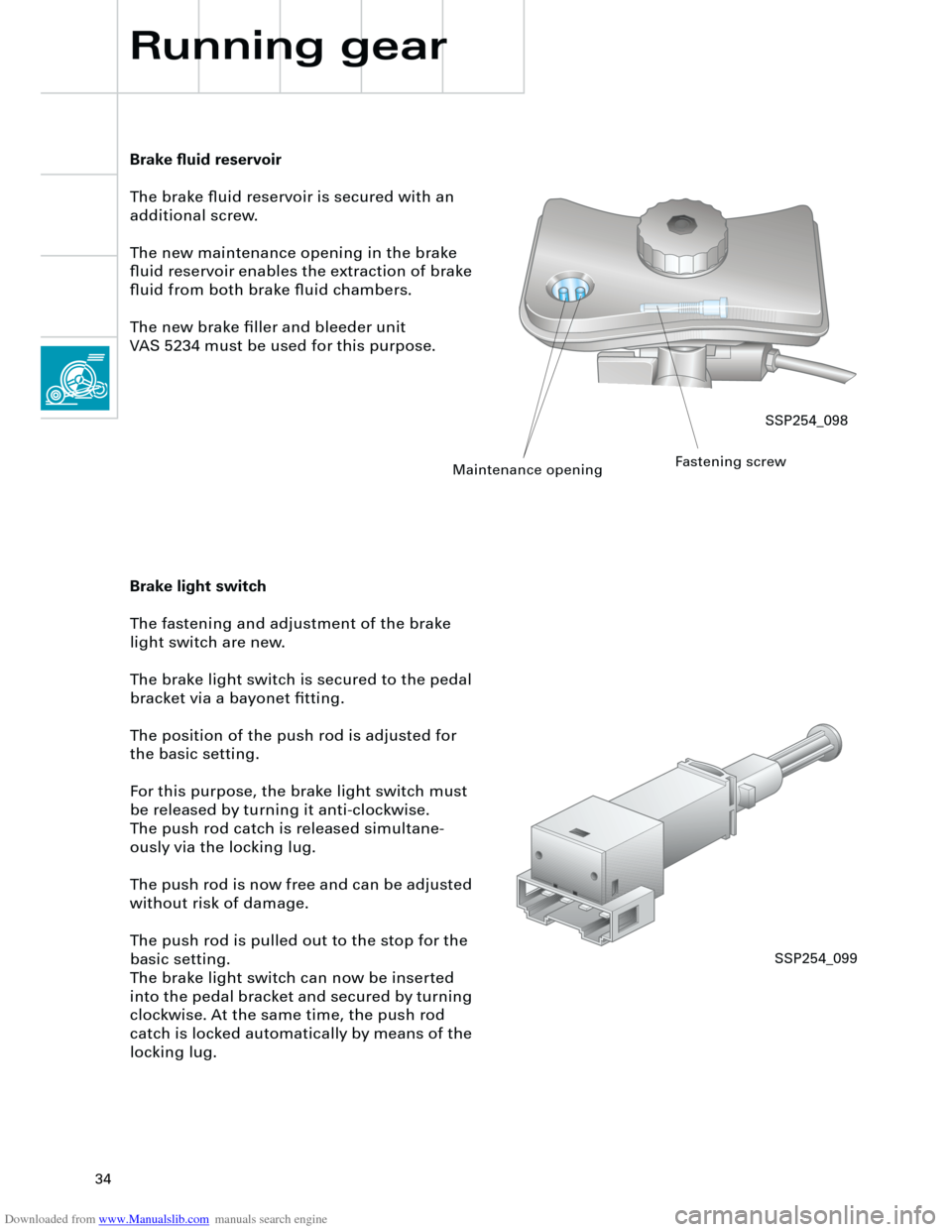
Brake fluid reservoir
The brake fluid reservoir is secured with an
additional screw.
The new maintenance opening in the brake
fluid reservoir enables the extraction of brake
fluid from both brake fluid chambers.
The new brake filler and bleeder unit
VAS 5234 must be used for this purpose.
Brake light switch
The fastening and adjustment of the brake
light switch are new.
The brake light switch is secured to the pedal
bracket via a bayonet fitting.
The position of the push rod is adjusted for
the basic setting.
For this purpose, the brake light switch must
be released by turning it anti-clockwise.
The push rod catch is released simultane-
ously via the locking lug.
The push rod is now free and can be adjusted
without risk of damage.
The push rod is pulled out to the stop for the
basic setting.
The brake light switch can now be inserted
into the pedal bracket and secured by turning
clockwise. At the same time, the push rod
catch is locked automatically by means of the
locking lug.
SSP254_098
Maintenance openingFastening screw
SSP254_099
Page 35 of 88
Downloaded from www.Manualslib.com manuals search engine
35
Notes
Page 36 of 88
Downloaded from www.Manualslib.com manuals search engine
36
Front airbag crash sen-
sor, driver’s side G283
Vehicle electrical system
Electrical system
Control unit for
coolant fan,
Stage 1+2 J293Control unit
for ESP J104 Control unit for
telematics J499
Control unit for
mobile phone control
electronics J412
Front airbag crash
sensor, passen-
ger’s side G284
Control unit
for Motronic J220
Control unit for auto-
matic gearbox J217
Control unit for headlamp
range control J431Chip card
reader R99
Steering column
switch module J527
Battery
Control unit with
display in dash panel
insert J285
Page 37 of 88
Downloaded from www.Manualslib.com manuals search engine
37
Side airbag crash sensor,
driver’s side G179
Control unit for
parking aid J446
Airbag control
unit J234Side airbag crash sensor, rear
driver’s side G256
passenger’s side G257
Control unit for
tyre pressure
monitor J502
SSP254_008
Door control units,
passenger side J387
rear right,
optional J389
ESP sensor
Control unit for trailer
recognition J345
Central control unit for
convenience system J393
Side airbag crash sensor,
passenger’s side G180
Door control unit,
driver’s side J386,
rear left, optional J388
Control unit for vehicle electri-
cal system J519
Page 38 of 88
Downloaded from www.Manualslib.com manuals search engine
38
Electrical system
NOX sensor
(USA only) Diagnosis system
CAN BUS networking
The ignition switch signals and the
control buttons for multifunction
and "tiptronic" steering wheel are
registered via the steering column
electronics.
G85
J162J502
R99
J401
Gate-
way
J220
J234
J387 J386
J388 J389
J393 J217
J104
J453 J446
J402 E87
J519
J136 J345J526J499 J507
J527
J285
R94
TRACK
SEEK
CD CDC
AM
FM1DOLBY SYSTEM2
12
TA P EPLAY SDEBASS MIDDLE TREBLE BALANCE FADER123456
EJECTAudi symphony
AS
TP
RDS
RANDOM FR FF
TUNE SCAN
EJECT
R
J527
R
T+-
Page 39 of 88

Downloaded from www.Manualslib.com manuals search engine
39
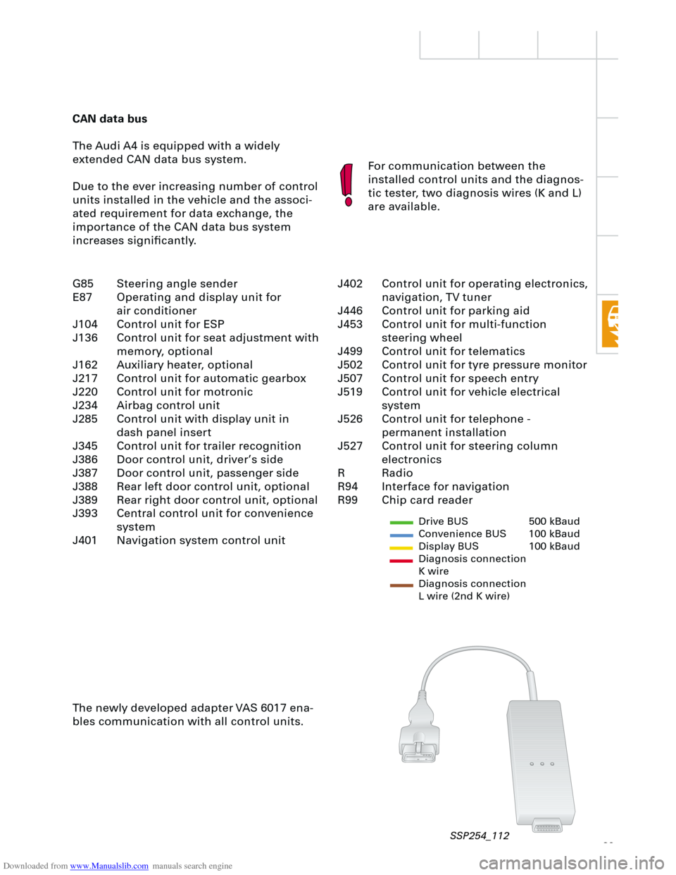
CAN data bus
The Audi A4 is equipped with a widely
extended CAN data bus system.
Due to the ever increasing number of control
units installed in the vehicle and the associ-
ated requirement for data exchange, the
importance of the CAN data bus system
increases significantly.For communication between the
installed control units and the diagnos-
tic tester, two diagnosis wires (K and L)
are available.
The newly developed adapter VAS 6017 ena-
bles communication with all control units.
Drive BUS 500 kBaud
Convenience BUS 100 kBaud
Display BUS 100 kBaud
Diagnosis connection
K wire
Diagnosis connection
L wire (2nd K wire)
J402 Control unit for operating electronics,
navigation, TV tuner
J446 Control unit for parking aid
J453 Control unit for multi-function
steering wheel
J499 Control unit for telematics
J502 Control unit for tyre pressure monitor
J507 Control unit for speech entry
J519 Control unit for vehicle electrical
system
J526 Control unit for telephone -
permanent installation
J527 Control unit for steering column
electronics
R Radio
R94 Interface for navigation
R99 Chip card reader G85 Steering angle sender
E87 Operating and display unit for
air conditioner
J104 Control unit for ESP
J136 Control unit for seat adjustment with
memory, optional
J162 Auxiliary heater, optional
J217 Control unit for automatic gearbox
J220 Control unit for motronic
J234 Airbag control unit
J285 Control unit with display unit in
dash panel insert
J345 Control unit for trailer recognition
J386 Door control unit, driver’s side
J387 Door control unit, passenger side
J388 Rear left door control unit, optional
J389 Rear right door control unit, optional
J393 Central control unit for convenience
system
J401 Navigation system control unit
SSP254_112
Page 40 of 88
Downloaded from www.Manualslib.com manuals search engine
40
Electrical system
Setting buttons for digital clock,
date and instrument illuminationAuto-check system
Call-up button for
service interval
indicatorReset button for trip
recorder
Dash panel insert
There are two dash panel insert versions:
– "lowline"
– "highline"
The "highline" version is equipped with a
high-quality colour display for the driver infor-
mation system and is installed in vehicles
with navigation systems as well as telematics.The dash panel insert of the new Audi A4 is
equipped with
– the gateway for linking the three data bus
systems: drive, convenience, information
– and the immobiliser III.
Cruise control system ON
SSP254_012