Page 25 of 96
INSTRUMENT AND CONTROL FUNCTIONS
3-10
3
EAU01710
SeatsPassenger seat
To removeRemove the nut and pull the seat up-
ward.To install
Insert the projection on the front of the
seat into the seat holder and install the
nut.Rider seat
To remove
Remove the passenger seat. Then, re-
move the bolts and bracket and pull the
seat upward.
1. Nut
1. Projection
2. Seat holder
1. Bolt (´ 2)
2. Bracket
E_5el_Functions.fm Page 10 Monday, May 1, 2000 9:38 AM
Page 26 of 96
INSTRUMENT AND CONTROL FUNCTIONS
3-11
3
To install
1. Insert the projections on the front
of the rider seat into the seat hold-
ers, then place the seat in the orig-
inal position.
2. Install the bracket and the bracket
bolts.
3. Install the passenger seat.NOTE:@ Make sure that the seats are securely
fitted. @
EAU00260
Helmet holderTo open the helmet holder, insert the
key in the lock and turn it as shown. To
lock the helmet holder, replace the
holder in its original position.
EW000030
WARNING
@ Never ride with a helmet in the hel-
met holder. The helmet may hit ob-
jects, causing loss of control and
possibly an accident. @
EAU01869
Storage compartmentThe storage compartment is located on
the left side of the motorcycle.
1. Projection (´ 2)
2. Seat holder (´ 2)
1. Helmet holder
1. Compartment cover
2. Lock
E_5el_Functions.fm Page 11 Monday, May 1, 2000 9:38 AM
Page 27 of 96
INSTRUMENT AND CONTROL FUNCTIONS
3-12
3
To open
Slide the lock cover open, insert the
key in the lock and turn it clockwise.Then, pull the storage compartment
cover out as shown.To close
Place the storage compartment cover
in its original position as shown. Then,
turn the key counterclockwise and re-
move it. Close the lock cover.
1. Storage compartment
1. Storage compartment
E_5el_Functions.fm Page 12 Monday, May 1, 2000 9:38 AM
Page 28 of 96
INSTRUMENT AND CONTROL FUNCTIONS
3-13
3
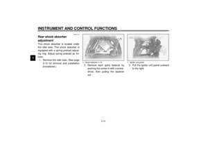
EAU01713
Rear shock absorber
adjustmentThis shock absorber is located under
the rider seat. This shock absorber is
equipped with a spring preload adjust-
ing ring. Adjust spring preload as fol-
lows.
1. Remove the rider seat. (See page
3-10 for removal and installation
procedures.)2. Remove each quick fastener by
pushing the center in with a screw-
driver, then pulling the fastener
out.3. Pull the ignitor unit panel outward
to the right.
1. Quick fastener (´ 3)
1. Ignitor unit panel
E_5el_Functions.fm Page 13 Monday, May 1, 2000 9:38 AM
Page 29 of 96
INSTRUMENT AND CONTROL FUNCTIONS
3-14
3
4. Remove the mud guard by remov-
ing each quick fastener.5. Turn the adjusting ring in direction
a
to increase spring preload and in
direction
b to decrease spring
preload.
6. Make sure that the appropriate
notch in the adjusting ring is
aligned with the position indicator
on the rear shock absorber.
CI-15E
NOTE:@ When adjusting, use the special
wrench which is included in the owner’s
tool kit. @7. Install the mud guard and ignitor
unit panel.NOTE:@ When installing a quick fastener, push
its pin back so that it will protrude from
the fastener head, then insert the fas-
tener and push the protruding pin in un-
til it is flush with the fastener head. @8. Install the rider seat.
1. Quick fastener (´ 3)
2. Mud guard
1. Adjusting ring
2. Position indicator
3. Special wrench
SoftStan-
dardHard
Adjusting
position12 3 4567
After removal Before installation
E_5el_Functions.fm Page 14 Monday, May 1, 2000 9:38 AM
Page 30 of 96

INSTRUMENT AND CONTROL FUNCTIONS
3-15
3
EAU00315
WARNING
@ This shock absorber contains high-
ly pressurized nitrogen gas. Read
and understand the following infor-
mation before handling the shock
absorber. The manufacturer cannot
be held responsible for property
damage or personal injury that may
result from improper handling.l
Do not tamper with or attempt to
open the cylinder assembly.
l
Do not subject the shock ab-
sorber to an open flame or other
high heat source. This may
cause the unit to explode due to
excessive gas pressure.
l
Do not deform or damage the
cylinder in any way. Cylinder
damage will result in poor
damping performance.
l
Take your shock absorber to a
Yamaha dealer for any service.
@
EAU01172
Luggage strap holdersThere is a luggage strap holder located
at each passenger footrest.
EAU00330
SidestandThis model is equipped with an ignition
circuit cut-off system. The motorcycle
must not be ridden when the sidestand
is down. The sidestand is located on
the left side of the frame. (Refer to
page 5-1 for an explanation of this sys-
tem.)
EW000044
WARNING
@ This motorcycle must not be operat-
ed with the sidestand in the down po-
sition. If the stand is not properly
retracted, it could contact the ground
and distract the operator, resulting in
a possible loss of control. Yamaha
has designed into this motorcycle a
lockout system to assist the operator
in fulfilling the responsibility of re-
tracting the sidestand. Please check
carefully the operating instructions
listed below and if there is any indi-
cation of a malfunction, return the
motorcycle to a Yamaha dealer im-
mediately for repair. @
1. Luggage strap holder (´ 2)
E_5el_Functions.fm Page 15 Monday, May 1, 2000 9:38 AM
Page 31 of 96
INSTRUMENT AND CONTROL FUNCTIONS
3-16
3
EAU00331
Sidestand/clutch switch
operation checkCheck the operation of the sidestand
switch and clutch switch against the in-
formation below.CD-11E
EW000045
WARNING
@ If improper operation is noted, con-
sult a Yamaha dealer immediately. @
TURN THE MAIN SWITCH TO “ON”
AND THE ENGINE STOP SWITCH TO
“”.TRANSMISSION IS IN GEAR AND
SIDESTAND IS UP.PULL IN CLUTCH LEVER AND
PUSH THE START SWITCH.ENGINE WILL START.SIDESTAND IS DOWN.CLUTCH SWITCH IS OK.
ENGINE WILL STALL.SIDESTAND SWITCH IS OK.
E_5el_Functions.fm Page 16 Monday, May 1, 2000 9:38 AM
Page 32 of 96
E_5el_Functions.fm Page 17 Monday, May 1, 2000 9:38 AM