Page 41 of 86

6-9
PERIODIC MAINTENANCE AND MINOR REPAIR
1
2
3
4
5
6
7
8
9
1
Installation
1. Measure the electrode gap
with a wire thickness gauge
and, if necessary, adjust the
gap to specification.
2. Clean the gasket surface. Wipe
off any grime from the
threads.
3. Install the spark plug and tight-
en it to the specified torque.
1. Spark plug gap
NOTE:
If a torque wrench is not available
when you are installing a spark
plug, a good estimate of the cor-
rect torque is 1/4 to 1/2 turn past
finger tight. Have the spark plug
tightened to the specified torque as
soon as possible.
4. Install the spark plug cap.
EAU00517*
Engine oil
Oil level measurement
1. Place the motorcycle on a level
place and hold it in an upright
position. Warm up the engine
for several minutes.
NOTE:
Be sure the motorcycle is posi-
tioned straight up when checking
the oil level. A slight tilt toward the
side can result in false readings.
Spark plug gap:
0.6 ~ 0.7 mm
Tightening torque:
Spark plug:
17.5 Nm (1.75 m·kg)
5EK-9-E1 (TW125)<3.1> 4/6/0 11:50 PM Page 39
Page 42 of 86
6-10
PERIODIC MAINTENANCE AND MINOR REPAIR
1
2
3
4
5
6
7
8
92. With the engine stopped,
check the oil level through the
level window located at the
lower part of the right side
crankcase cover.
NOTE:
Wait a few minutes until the oil
level settles before checking.
3. The oil level should be
between the maximum and
minimum marks. If the level is
low, add sufficient oil to raise
it to the proper level.
1. Maximum level mark
2. Minimum level mark
Engine oil replacement
1. Warm up the engine for a few
minutes.
2. Stop the engine. Place an oil
pan under the engine and
remove the oil filler cap.
1. Engine oil filler cap
3. Remove the drain bolts.
1. Engine oil drain bolt
1
1
1
2
5EK-9-E1 (TW125)<3.1> 4/6/0 11:50 PM Page 40
Page 43 of 86
6-11
PERIODIC MAINTENANCE AND MINOR REPAIR
1
2
3
4
5
6
7
8
9
EC000070
cC
When removing the oil drain bolt,
the O-ring, compression spring,
and oil strainer will fall out. Take
care not to lose these parts.
1. Strainer
2. Compression spring
3. O-ring
NOTE:
The oil filter cover is secured by
two screws and a drain bolt.
Remove the drain bolt to drain the
filter cavity.
1. Bolts (´3)
2. Engine oil drain bolt
4. Remove the filter cover screws
and the oil filter cover.
5. Remove the oil filter element
and O-ring.
6. Clean the oil filter and strainer
with solvent. Replace if neces-
sary.
7. Check the O-rings. If damaged,
replace.
8. Install the filter cover, screws
and drain bolts. Tighten the
drain bolts to the specified
tightening torques.
NOTE:
Make sure the O-ring is seated
properly.
1. Oil filter element
2. O-ring
12 3
1 21
2
5EK-9-E1 (TW125)<3.1> 4/6/0 11:50 PM Page 41
Page 44 of 86

6-12
PERIODIC MAINTENANCE AND MINOR REPAIR
1
2
3
4
5
6
7
8
9
1
2
2
EAU01501*Air filter
The air filter should be cleaned at
the specified intervals. It should be
cleaned more frequently when rid-
ing in unusually wet or dusty
areas.
Air filter element cleaning
1. Remove panel A. (See page
6-6 for removal and installa-
tion procedures.)
2. Remove the air filter case fit-
ting screws and the filter case
cover.
1. Air filter case cover
2. Screw (´4)EC000066
cC
8Do not put in any chemical
additives. Engine oil also lubri-
cates the clutch and additives
could cause clutch slippage.
8Be sure no foreign material
enters the crankcase.
10. Start the engine and warm up
for a few minutes. While
warming up, check for oil leak-
age. If oil leakage is found,
stop the engine immediately
and check for the cause.
EC000071
cC
Before reinstalling the oil drain
bolt, do not forget to install the O-
ring, compression spring, and oil
strainer in position.
9. Fill the engine with oil. Install
the oil filler cap and tighten. Tightening torque:
Drain bolt:
43 Nm (4.3 m·kg)
Filter cover screw:
7.0 Nm (0.7 m·kg)
Drain bolt (filter cover):
10 Nm (1.0 m·kg)
Recommended oil:
See page 8-1.
Total amount:
1.3 L
Periodic oil change:
1.0 L
With oil filter replacement:
1.1 L
5EK-9-E1 (TW125)<3.1> 4/6/0 11:50 PM Page 42
Page 45 of 86

6-13
PERIODIC MAINTENANCE AND MINOR REPAIR
1
2
3
4
5
6
7
8
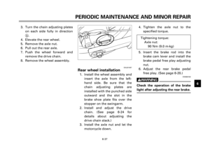
9 3. Remove the air filter from the
case.
4. Remove the air filter element
from its frame and clean it
with solvent. After cleaning,
remove the remaining solvent
by squeezing the element.
5. Apply recommended oil to the
entire surface of the element
and squeeze out the excess oil.
The element should be wet but
not dripping.
1. Air filter element
2. Air filter element frame
6. Install the air filter frame onto
the air filter and install the
assembly in the case.
7. Install the air filter case cover
and panel.
EC000082
cC
8Make sure the air filter is prop-
erly seated in the air filter
case.
8The engine should never be
run without the air filter
installed. Excessive piston
and/or cylinder wear may
result.
Air filter case drain hose cleaning
Frequently check the hose at the
bottom of the air filter case. If dirt
or water is visible, remove and
clean the hose, then reinstall it.
1. Hose
Recommended oil:
Engine oil
1
21
5EK-9-E1 (TW125)<3.1> 4/6/0 11:50 PM Page 43
Page 46 of 86

6-14
PERIODIC MAINTENANCE AND MINOR REPAIR
1
2
3
4
5
6
7
8
9
EAU00629Carburetor adjustment
The carburetor is a vital part of the
engine and requires very sophisti-
cated adjustment. Most adjust-
ments should be left to a Yamaha
dealer who has the professional
knowledge and experience to do
so. However, the following may be
serviced by the owner as part of
routine maintenance.
EC000094
cC
The carburetor was set at the
Yamaha factory after many tests. If
the settings are changed, poor
engine performance and damage
may result.
EAU01168Idle speed adjustment
NOTE:
A diagnostic tachometer must be
used for this procedure.
1. Attach the tachometer. Start
the engine and warm it up for
a few minutes at approximate-
ly 1,000 to 2,000 r/min.
Occasionally rev the engine to
4,000 to 5,000 r/min. The
engine is warm when it quickly
responds to the throttle.2. Set the idle to the specified
engine speed by adjusting the
throttle stop screw. Turn the
screw in direction ato
increase engine speed and in
direction bto decrease engine
speed.
NOTE:
If the specified idle speed cannot
be obtained by performing the
above adjustment, consult a
Yamaha dealer.
1. Throttle stop screw
1
ab
Standard idle speed:
1,300 ~ 1,500 r/min
5EK-9-E1 (TW125)<3.1> 4/6/0 11:50 PM Page 44
Page 47 of 86
6-15
PERIODIC MAINTENANCE AND MINOR REPAIR
1
2
3
4
5
6
7
8
9
EAU00634Throttle cable free play
adjustment
NOTE:
Before checking the throttle cable
free play, the engine idling speed
should be adjusted.
Adjust the throttle cable by turning
the adjusting nut so that specified
free play at the throttle grip is
obtained.
1. Adjusting nut
2. Locknut
c. Free play
1. Loosen the locknut.
2. Turn the adjusting nut in direc-
tion ato increase free play
and in direction bto decrease
free play.
3. Tighten the locknut.
EAU00637Valve clearance adjustment
The correct valve clearance
changes with use, resulting in
improper fuel/air supply or engine
noise. To prevent this, the valve
clearance must be adjusted regu-
larly. This adjustment however,
should be left to a professional
Yamaha service technician.
1
2a
bc
Free play:
3 ~ 5 mm
5EK-9-E1 (TW125)<3.1> 4/6/0 11:50 PM Page 45
Page 48 of 86

6-16
PERIODIC MAINTENANCE AND MINOR REPAIR
1
2
3
4
5
6
7
8
9
EAU00652Tires
To ensure maximum performance,
long service and safe operation,
note the following:
Tire air pressure
Always check and adjust the tire
pressure before operating the
motorcycle.
EW000082
w
Tire inflation pressure should be
checked and adjusted when the
temperature of the tire equals the
ambient air temperature. Tire infla-
tion pressure must be adjusted
according to total weight of cargo,
rider, passenger, and accessories
(fairing, saddlebags, etc. if
approved for this model), and vehi-
cle speed.
EW000083
w
Proper loading of your motorcycle
is important for several character-
istics of your motorcycle, such as
handling, braking, performance
and safety. Do not carry loosely
packed items that can shift.
Securely pack your heaviest items
close to the center of the motorcy-
cle, and distribute the weight
evenly from side to side. Properly
adjust the suspension for your
load, and check the condition and
pressure of your tires. NEVER
OVERLOAD YOUR MOTORCYCLE.
Make sure the total weight of the
cargo, rider, passenger, and acces-
sories (fairing, saddlebags, etc. if
approved for this model) does not
exceed the maximum load of the
motorcycle. Operation of an over-
loaded motorcycle could cause tire
damage, an accident, or even
injury.
* Load is the total weight of cargo, rider, passen-
ger and accessories.
Maximum load* 180 kg
Cold tire pressure Front Rear
150 kPa 150 kPa
Up to 80 kg (1.50 kg/cm
2, (1.50 kg/cm2,1.50 bar) 1.50 bar)
80 kg load -150 kPa 175 kPa
Maximum load*(1.50 kg/cm
2, (1.75 kg/cm2,1.50 bar) 1.75 bar)
125 kPa 125 kPa
Off-road riding (1.25 kg/cm
2, (1.25 kg/cm2,
1.25 bar) 1.25 bar)
5EK-9-E1 (TW125)<3.1> 4/6/0 11:50 PM Page 46