Page 17 of 86
3-5
INSTRUMENT AND CONTROL FUNCTIONS
1
2
3
4
5
6
7
8
9
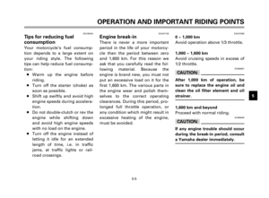
EAU00162Rear brake pedal
The rear brake pedal is on the right
side of the motorcycle. Press down
on the brake pedal to apply the
rear brake.
1. Rear brake pedal
EAU01498Fuel tank cap
To open
Insert the key and turn it 1/4 turn
counterclockwise. Open the cap by
turning it counterclockwise.
To close
Turn the cap clockwise with the
key inserted. To remove the key,
turn it clockwise to the original
position.
1. Fuel tank cap
NOTE:
This tank cap cannot be closed
unless the key is in the lock. The
key cannot be removed if the cap is
not locked properly.
EW000023
w
Be sure the cap is properly
installed and locked in place
before riding the motorcycle.
11
5EK-9-E1 (TW125)<3.1> 4/6/0 11:50 PM Page 15
Page 18 of 86
3-6
INSTRUMENT AND CONTROL FUNCTIONS
1
2
3
4
5
6
7
8
9
1
2
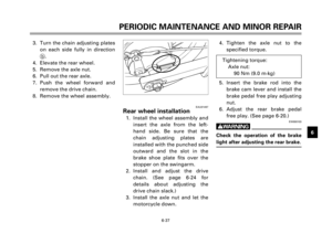
EAU01183
Fuel
Make sure there is sufficient fuel in
the tank. Fill the fuel tank to the
bottom of the filler tube as shown
in the illustration.
EW000130
w
Do not overfill the fuel tank. Avoid
spilling fuel on the hot engine. Do
not fill the fuel tank above the bot-
tom of the filler tube or it may
overflow when the fuel heats up
later and expands.
1. Filler tube
2. Fuel level
EAU00185
cC
Always wipe off spilled fuel imme-
diately with a dry and clean soft
cloth. Fuel may deteriorate painted
surfaces or plastic parts.
EAU00191
NOTE:
If knocking or pinging occurs, use a
different brand of gasoline or high-
er octane grade.
Recommended fuel:
Regular unleaded gasoline
with a research octane
number of 91 or higher.
Fuel tank capacity:
Total:
7.0 L
Reserve:
1.0 L
5EK-9-E1 (TW125)<3.1> 4/6/0 11:50 PM Page 16
Page 19 of 86
3-7
INSTRUMENT AND CONTROL FUNCTIONS
1
2
3
4
5
6
7
8
9
EAU01121Fuel cock
The fuel cock supplies fuel from
the tank to the carburetor while fil-
tering it also.
The fuel cock has three positions:
OFF
With the lever in this position, fuel
will not flow. Always return the
lever to this position when the
engine is not running.
1. Arrow mark positioned over “OFF”
ON
With the lever in this position, fuel
flows to the carburetor. Normal
riding is done with the lever in this
position.
1. Arrow mark positioned over “ON”
RES
This indicates reserve. If you run
out of fuel while riding, move the
lever to this position. Fill the tank
at the first opportunity. Be sure to
set the fuel cock back to “ON” after
refueling!
1. Arrow mark positioned over “RES”
RES
ONFUEL
OFF
1
Off position
OFF
ONFUEL RES
1
RES
Reserve position
ONFUEL
RES
OFF
1ON
Normal position
5EK-9-E1 (TW125)<3.1> 4/6/0 11:50 PM Page 17
Page 20 of 86
3-8
INSTRUMENT AND CONTROL FUNCTIONS
1
2
3
4
5
6
7
8
9
EAU02976Starter (choke) “1”
Starting a cold engine requires a
richer air-fuel mixture. A separate
starter circuit supplies this mixture.
Move in direction ato turn on the
starter (choke).
Move in direction bto turn off the
starter (choke).
1. Starter (choke) “1”
EAU02934Steering lock
To lock the steering
Turn the handlebars all the way to
the right and open the steering
lock cover.
Insert the key and turn it 1/8 turn
counterclockwise. Then, push the
key in while turning the handlebars
slightly to the left and turn the key
1/8 turn clockwise.
Check that the steering is locked,
remove the key and close the lock
cover.
1. Steering lock
2. Cover
To unlock the steering
Insert the key, push it in and turn it
1/8 turn counterclockwise so that it
moves out. Then, release and
remove the key.
a
b
1
12
5EK-9-E1 (TW125)<3.1> 4/6/0 11:50 PM Page 18
Page 21 of 86
3-9
INSTRUMENT AND CONTROL FUNCTIONS
1
2
3
4
5
6
7
8
9
EAU01092Seat
To remove the seat, remove the
bolts.
1. Bolt (´2)
To install the seat, insert the pro-
jection on the front of the seat into
the holder and push down on the
seat, then tighten the bolts.
NOTE:
Make sure that the seat is securely
fitted.
1. Projection
2. Seat holder
EAU00260Helmet holder
To open the helmet holder, insert
the key in the lock and turn it as
shown. To lock the helmet holder,
replace the holder in its original
position.
EW000030
w
Never ride with a helmet in the
helmet holder. The helmet may hit
objects, causing loss of control
and possibly an accident.
1. Helmet holder
1
1
1
2
5EK-9-E1 (TW125)<3.1> 4/6/0 11:50 PM Page 19
Page 22 of 86

3-10
INSTRUMENT AND CONTROL FUNCTIONS
1
2
3
4
5
6
7
8
9
EAU01343Rear shock absorberEAU00315
w
This shock absorber contains high-
ly pressurized nitrogen gas. Read
and understand the following
information before handling the
shock absorber. The manufacturer
cannot be held responsible for
property damage or personal
injury that may result from
improper handling.
8Do not tamper with or
attempt to open the cylinder
assembly.
8Do not subject the shock
absorber to an open flame or
other high heat source. This
may cause the unit to explode
due to excessive gas pressure.
8Do not deform or damage the
cylinder in any way. Cylinder
damage will result in poor
damping performance.
8Take your shock absorber to a
Yamaha dealer for any service.
EAU00320Rear carrierEW000032
w
Do not exceed the load limit of
3 kg.
1. Rear carrier
EAU01493Luggage strap holders
There are four luggage strap hold-
ers below the rear carrier.
1. Luggage strap (´4)
11
1
5EK-9-E1 (TW125)<3.1> 4/6/0 11:50 PM Page 20
Page 23 of 86
3-11
INSTRUMENT AND CONTROL FUNCTIONS
1
2
3
4
5
6
7
8
9
EAU00330Sidestand
This model is equipped with an
ignition circuit cut-off system. The
motorcycle must not be ridden
when the sidestand is down. The
sidestand is located on the left side
of the frame. (Refer to page 5-1 for
an explanation of this system.)
EW000044
w
This motorcycle must not be oper-
ated with the sidestand in the
down position. If the stand is not
properly retracted, it could contact
the ground and distract the opera-
tor, resulting in a possible loss of
control. Yamaha has designed into
this motorcycle a lockout system
to assist the operator in fulfilling
the responsibility of retracting the
sidestand. Please check carefully
the operating instructions listed
below and if there is any indication
of a malfunction, return the motor-
cycle to a Yamaha dealer immedi-
ately for repair.
5EK-9-E1 (TW125)<3.1> 4/6/0 11:50 PM Page 21
Page 24 of 86
3-12
INSTRUMENT AND CONTROL FUNCTIONS
1
2
3
4
5
6
7
8
9
EAU00331Sidestand/clutch switch
operation check
Check the operation of the side-
stand switch and clutch switch
against the information below.
EW000045
w
If improper operation is noted,
consult a Yamaha dealer immedi-
ately.
SIDESTAND IS DOWN.
ENGINE WILL STALL.
SIDESTAND SWITCH IS OK.
TURN THE MAIN SWITCH TO “ON”
AND THE ENGINE STOP SWITCH TO
“#”.
TRANSMISSION IS IN GEAR AND
SIDESTAND IS UP.
PULL IN CLUTCH LEVER AND
PUSH THE START SWITCH.
ENGINE WILL START.
CLUTCH SWITCH IS OK.
5EK-9-E1 (TW125)<3.1> 4/6/0 11:50 PM Page 22


 “1”
Starting a cold engine requires a
richer air-fuel mixture. A separate
starter circuit supplies this mixture.
Move")

To install the seat, insert the pro-
jection on the front of the seat into
the h")

