Page 177 of 287
ENG
4 - 15
ARBRE A CAMES ET CULBUTEURS
NOCKENWELLE UND KIPPHEBEL
3. Auftragen:
lMolybdändisulfidöl
(auf Kipphebel und Kipphebelwelle)
4. Montieren:
lKipphebel 1
lKipphebelwelle 2 3. Appliquer:
lHuile au bisulfure de molybdène
(sur le culbuteur et l’axe de culbuteur)
4. Monter:
lCulbuteur 1
lAxe de culbuteur 2
Page 178 of 287
4 - 16
ENG
VALVES AND VALVE SPRINGS
Extent of removal:
1
Valves removal
Extent of removal Order Part name Q’ty Remarks
VALVES AND VALVE SPRINGS
REMOVAL
Preparation for removal Cylinder head Refer to “CYLINDER HEAD” section.
Rocker arm and camshaft Refer to “CAMSHAFT AND ROCKER
ARMS” section.
1 Valve cotter 4 Use special tool.
Refer to “REMOVAL POINTS”.
2 Spring retainer 2
3 Valve spring 2
4 Exhaust valve 1
5 Intake valve 1
6 Valve stem seal 2
1
Page 179 of 287

ENG
4 - 16
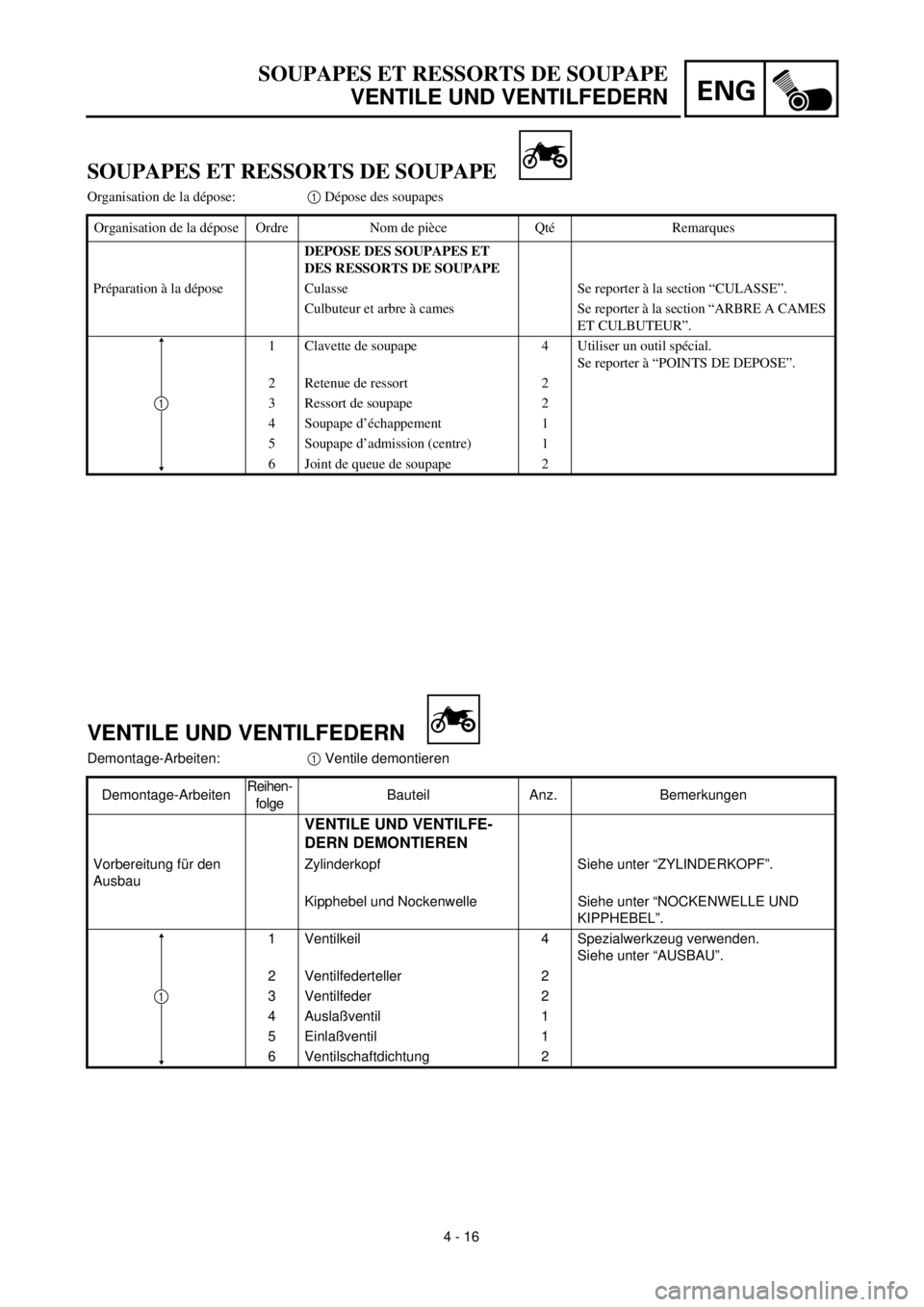
SOUPAPES ET RESSORTS DE SOUPAPE
VENTILE UND VENTILFEDERN
Demontage-Arbeiten:
1
Ventile demontieren
Demontage-ArbeitenReihen-
folgeBauteil Anz. Bemerkungen
VENTILE UND VENTILFE-
DERN DEMONTIEREN
Vorbereitung für den
AusbauZylinderkopf Siehe unter “ZYLINDERKOPF”.
Kipphebel und Nockenwelle Siehe unter “NOCKENWELLE UND
KIPPHEBEL”.
1 Ventilkeil 4 Spezialwerkzeug verwenden.
Siehe unter “AUSBAU”.
2 Ventilfederteller 2
3 Ventilfeder 2
4 Auslaßventil 1
5 Einlaßventil 1
6 Ventilschaftdichtung 2
1
SOUPAPES ET RESSORTS DE SOUPAPE
Organisation de la dépose:
1
Dépose des soupapes
Organisation de la dépose Ordre Nom de pièce Qté Remarques
DEPOSE DES SOUPAPES ET
DES RESSORTS DE SOUPAPE
Préparation à la dépose Culasse Se reporter à la section “CULASSE”.
Culbuteur et arbre à cames Se reporter à la section “ARBRE A CAMES
ET CULBUTEUR”.
1 Clavette de soupape 4 Utiliser un outil spécial.
Se reporter à “POINTS DE DEPOSE”.
2 Retenue de ressort 2
3 Ressort de soupape 2
4 Soupape d’échappement 1
5 Soupape d’admission (centre) 1
6 Joint de queue de soupape 2
1
Page 180 of 287
4 - 17
ENGVALVES AND VALVE SPRINGS
REMOVAL POINTS
Valve removal
1. Remove:
lValve cotters 1
NOTE:
Attach a valve spring compressor 2 between
the valve spring retainer and the cylinder head
to remove the valve cotters.
Valve spring compressor:
YM-01253/90890-01253
INSPECTION
Valve
1. Measure:
lStem-to-guide clearance
Out of specification ® Replace the
valve guide. Stem-to-guide clearance =
valve guide inside diameter a –
valve stem diameter b
Clearance (stem to guide):
Intake:
0.010 ~ 0.037 mm
(0.0004 ~ 0.0015 in)
: 0.08 mm (0.003 in)
Exhaust:
0.025 ~ 0.052 mm
(0.0010 ~ 0.0020 in)
: 0.10 mm (0.004 in)
2. Measure:
lRunout (valve stem)
Out of specification ® Replace.
Runout limit:
0.02 mm (0.0008 in)
Page 181 of 287

ENG
4 - 17
SOUPAPES ET RESSORTS DE SOUPAPE
VENTILE UND VENTILFEDERN
AUSBAU
Ventile demontieren
1. Demontieren:
lVentilkeile 1
HINWEIS:
Zum Ausbau der Ventilkeile einen Ventilfeder-
spanner 2 zwischen Ventilfederteller und Zy-
linderkopf ansetzen.
Ventilfederspanner
YM-01253/90890-01253
PRÜFUNG
Ventil
1. Messen:
lVentilschaftspiel
Unvorschriftsmäßig ® Ventilführung er-
neuern. Ventilschaftspiel =
Ventilführungsdurchmesser a –
Ventilschaftdurchmesser b
Ventilschaftspiel
Einlaß
0,010–0,037 mm
0,08 mm
Auslaß
0,025–0,052 mm
0,10 mm
2. Messen:
lVentilschaftschlag
Unvorschriftsmäßig ® Erneuern.
Max. zulässiger Schlag
0,02 mm
POINTS DE DEPOSE
Dépose des soupapes
1. Déposer:
lClavettes de soupape 1
N.B.:
Fixer un compresseur de ressort de soupape 2
entre la retenue de ressort de soupape et la culasse
pour retirer les clavettes de soupape.
Compresseur de ressort de soupape:
YM-01253/90890-01253
CONTROLE
Soupape
1. Mesurer:
lJeu de queue dans le guide
Hors spécifications ® Remplacer le guide
de soupape. Jeu de queue dans le guide de soupape =
Diamètre intérieur de guide de soupape a
– Diamètre de queue de soupape b
Jeu (entre queue et guide):
Admission:
0,010 à 0,037 mm
(0,0004 à 0,0015 in)
: 0,08 mm (0,003 in)
Echappement:
0,025 à 0,052 mm
(0,0010 à 0,0020 in)
: 0,10 mm (0,004 in)
2. Mesurer:
lOvalisation (queue de soupape)
Hors spécifications ® Remplacer.
Limite de déformation:
0,02 mm (0,0008 in)
Page 182 of 287

4 - 18
ENGVALVES AND VALVE SPRINGS
Valve spring
1. Measure:
lValve spring free length a
Out of specification ® Replace.
2. Measure:
lSpring tilt a
Out of specification ® Replace.
Free length (valve spring):
Intake:
28.32 mm (1.11 in)
: 26.9 mm (1.06 in)
Exhaust:
28.32 mm (1.11 in)
: 26.9 mm (1.06 in)
Spring tilt limit:
Intake:
2.5˚/1.2 mm (0.05 in)
Exhaust:
2.5˚/1.2 mm (0.05 in)
Valve seat
1. Measure:
lValve seat width a
Out of specification ® Reface the valve
seat.
Valve seat width:
Intake:
0.9 ~ 1.1 mm (0.0354 ~ 0.0433 in)
: 1.6 mm (0.06 in)
Exhaust:
0.9 ~ 1.1 mm (0.0354 ~ 0.0433 in)
: 1.6 mm (0.06 in)
Measurement steps:
lApply Mechanic’s blueing dye (Dykem) b
to the valve face.
lInstall the valve into the cylinder head.
lPress the valve through the valve guide
and onto the valve seat to make a clear
pattern.
lMeasure the valve seat width. Where the
valve seat and valve face made contact,
blueing will have been removed.
lIf the valve seat is too wide, too narrow, or
the seat is not centered, the valve seat
must be refaced.
Page 183 of 287

ENG
4 - 18
SOUPAPES ET RESSORTS DE SOUPAPE
VENTILE UND VENTILFEDERN
Ventilfeder
1. Messen:
lVentilfederlänge (entspannt) a
Unvorschriftsmäßig ® Erneuern.
2. Messen:
lRechtwinkligkeit a
Grenzwert überschritten ® Erneuern.
Ungespannte Länge (Ventilfeder)
Einlaß
28,32 mm
26,9 mm
Auslaß
28,32 mm
26,9 mm
Rechtwinkligkeitsgrenzwert
Einlaß
2,5˚/1,2 mm
Auslaß
2,5˚/1,2 mm
Ventilsitz
1. Messen:
lVentilsitzbreite a
Unvorschriftsmäßig ® Ventilsitz nach-
arbeiten.
Ventilsitzbreite
Einlaß
0,9–1,1 mm
1,6 mm
Auslaß
0,9–1,1 mm
1,6 mm
Arbeitsschritte
lTuschierfarbe b auf den Ventilkegel auf-
tragen.
lVentil in den Zylinderkopf einsetzen.
lVentil fest gegen den Sitz pressen, um
einen deutlichen Abdruck zu erhalten.
lVentilsitzbreite messen. Die Kontaktfläche
von Ventilteller und Ventilsitz ist aufgrund
der Farbverteilung sichtbar.
lIst der Sitz zu breit, zu schmal oder außer-
mittig, muß der Ventilsitz nachbearbeitet
werden.
Ressort de soupape
1. Mesurer:
lLongueur libre du ressort de soupape a
Hors spécifications ® Remplacer.
2. Mesurer:
lInclinaison du ressort a
Hors spécifications ® Remplacer.
Longueur libre (ressort de soupape):
Admission:
28,32 mm (1,11 in)
: 26,9 mm (1,06 in)
Echappement:
28,32 mm (1,11 in)
: 26,9 mm (1,06 in)
Limite d’inclinaison du ressort:
Admission:
2,5˚/1,2 mm (0,05 in)
Echappement:
2,5˚/1,2 mm (0,05 in)
Siège de soupape
1. Mesurer:
lLargeur de siège de soupape a
Hors spécifications ® Surfacer le siège de
soupape.
Largeur du siège de soupape:
Admission:
0,9 à 1,1 mm (0,0354 à 0,0433 in)
: 1,6 mm (0,06 in)
Echappement:
0,9 à 1,1 mm (0,0354 à 0,0433 in)
: 1,6 mm (0,06 in)
Etapes de la mesure:
lAppliquer du bleu de mécanicien (Dykem) b
sur la face de la soupape.
lInstaller la soupape dans la culasse.
lPresser la soupape à travers le guide de sou-
pape et sur le siège de soupape de manière à
laisser une trace nette.
lMesurer la largeur du siège de soupape. Le
bleu aura disparu aux endroits où la soupape et
son siège entrent en contact.
lSi le siège de soupape est trop large, trop étroit
ou si le siège n’est pas centré, il faut le surfa-
cer.
Page 184 of 287

4 - 19
ENGVALVES AND VALVE SPRINGS
2. Lap:
lValve face
lValve seat
NOTE:
After refacing the valve seat or replacing the
valve and valve guide, the valve seat and
valve face should be lapped.
Lapping steps:
lApply a coarse lapping compound to the
valve face.
lApply molybdenum disulfide oil to the
valve stem.
lInstall the valve into the cylinder head.
lTurn the valve until the valve face and
valve seat are evenly polished, then clean
off all of the compound.
lApply a fine lapping compound to the
valve face and repeat the above steps.
lApply Mechanic’s blueing dye (Dykem) to
the valve face.
lInstall the valve into the cylinder head.
lPress the valve through the valve guide
and onto the valve seat to make a clear
pattern.
lMeasure the valve seat width again. If the
valve seat width is out of specification,
reface and relap the valve seat.
CAUTION:
Do not let the compound enter the gap
between the valve stem and the guide.
NOTE:
For best lapping results, lightly tap the valve
seat while rotating the valve back and forth
between your hands.
NOTE:
After every lapping operation be sure to
clean off all of the compound from the valve
face and valve seat.