Page 61 of 4770
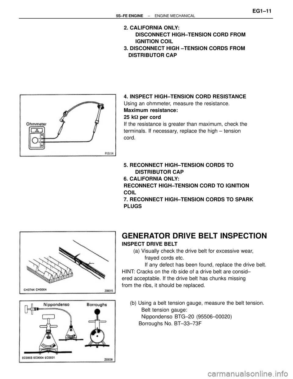
GENERATOR DRIVE BELT INSPECTION
INSPECT DRIVE BELT
(a) Visually check the drive belt for excessive wear,
frayed cords etc.
If any defect has been found, replace the drive belt.
HINT: Cracks on the rib side of a drive belt are consid±
ered acceptable. If the drive belt has chunks missing
from the ribs, it should be replaced.4. INSPECT HIGH±TENSION CORD RESISTANCE
Using an ohmmeter, measure the resistance.
Maximum resistance:
25 k� per cord
If the resistance is greater than maximum, check the
terminals. If necessary, replace the high ± tension
cord.
5. RECONNECT HIGH±TENSION CORDS TO
DISTRIBUTOR CAP
6. CALIFORNIA ONLY:
RECONNECT HIGH±TENSION CORD TO IGNITION
COIL
7. RECONNECT HIGH±TENSION CORDS TO SPARK
PLUGS2. CALIFORNIA ONLY:
DISCONNECT HIGH±TENSION CORD FROM
IGNITION COIL
3. DISCONNECT HIGH ±TENSION CORDS FROM
DISTRIBUTOR CAP
(b) Using a belt tension gauge, measure the belt tension.
Belt tension gauge:
Nippondenso BTG±20 (95506±00020)
Borroughs No. BT±33±73F
± 5S±FE ENGINEENGINE MECHANICALEG1±11
Page 62 of 4770
Drive belt tension:
w/ A/C
New belt
175 + 5 lbf
Used belt
130 + 10 lbf
w/o A/C
New belt
125 + 25 lbf
Used belt
95 + 20 lbf
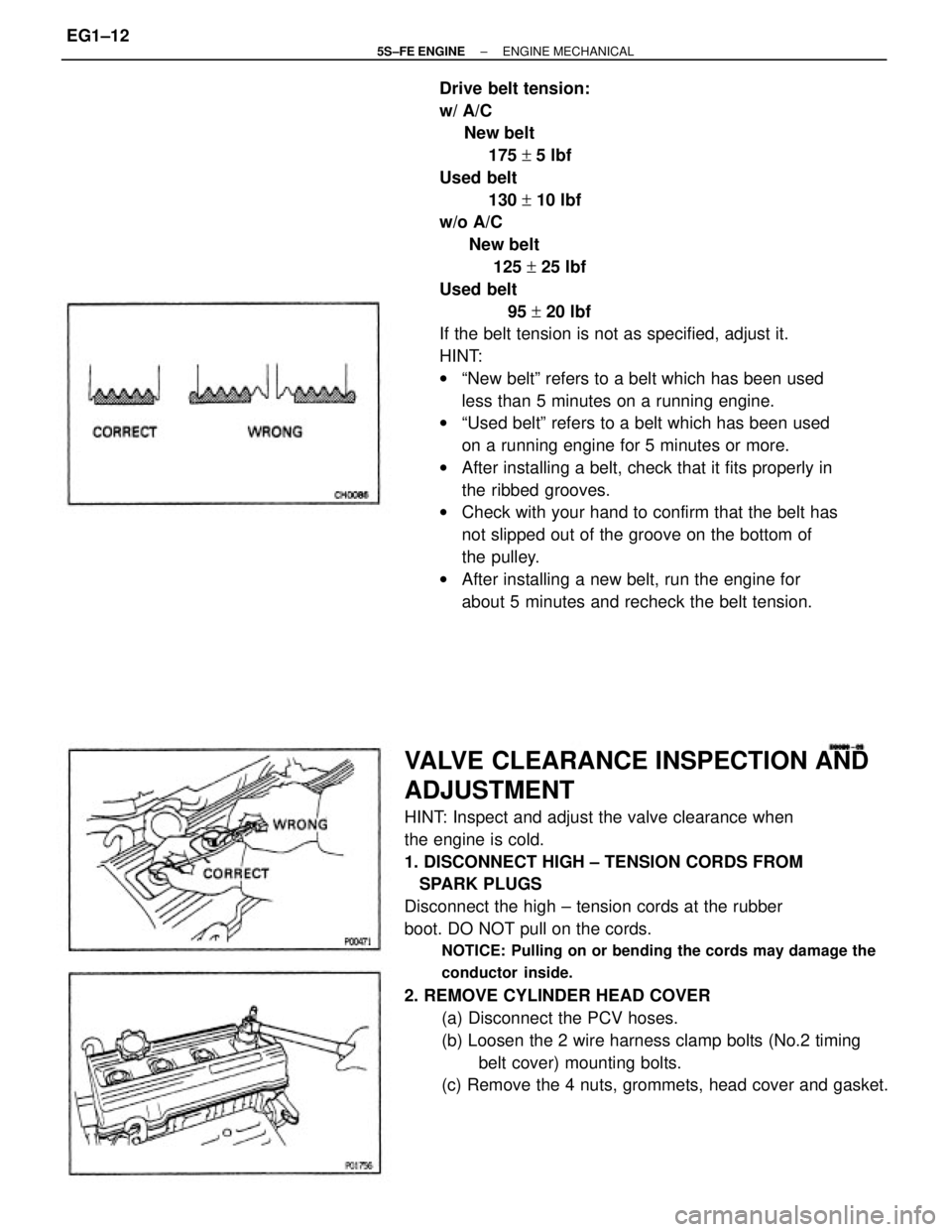
If the belt tension is not as specified, adjust it.
HINT:
wªNew beltº refers to a belt which has been used
less than 5 minutes on a running engine.
wªUsed beltº refers to a belt which has been used
on a running engine for 5 minutes or more.
wAfter installing a belt, check that it fits properly in
the ribbed grooves.
wCheck with your hand to confirm that the belt has
not slipped out of the groove on the bottom of
the pulley.
wAfter installing a new belt, run the engine for
about 5 minutes and recheck the belt tension.
VALVE CLEARANCE INSPECTION AND
ADJUSTMENT
HINT: Inspect and adjust the valve clearance when
the engine is cold.
1. DISCONNECT HIGH ± TENSION CORDS FROM
SPARK PLUGS
Disconnect the high ± tension cords at the rubber
boot. DO NOT pull on the cords.
NOTICE: Pulling on or bending the cords may damage the
conductor inside.
2. REMOVE CYLINDER HEAD COVER
(a) Disconnect the PCV hoses.
(b) Loosen the 2 wire harness clamp bolts (No.2 timing
belt cover) mounting bolts.
(c) Remove the 4 nuts, grommets, head cover and gasket.
± 5S±FE ENGINEENGINE MECHANICALEG1±12
Page 81 of 4770
TIMING BELT COMPONENTS INSPECTION
1. INSPECT TIMING BELT
NOTICE:
wDo not bend, twist or turn the timing belt Inside out.
wDo not allow the timing belt to come into contact
with oil, water or steam.
22. REMOVE CRANKSHAFT TIMING PULLEY
If the pulley cannot be removed by hand, use 2 screw±
drivers.
HINT: Position shop rags as shown to prevent
damage.20. REMOVE NO.1 IDLER PULLEY AND TENSION
SPRING
Remove the bolt, pulley and tension spring.
23. REMOVE OIL PUMP PULLEY
Using SST, remove the nut and pulley.
SST 09616±3001121. REMOVE NO.2 IDLER PULLEY
Remove the bolt and pulley.
± 5S±FE ENGINEENGINE MECHANICALEG1±31
Page 413 of 4770
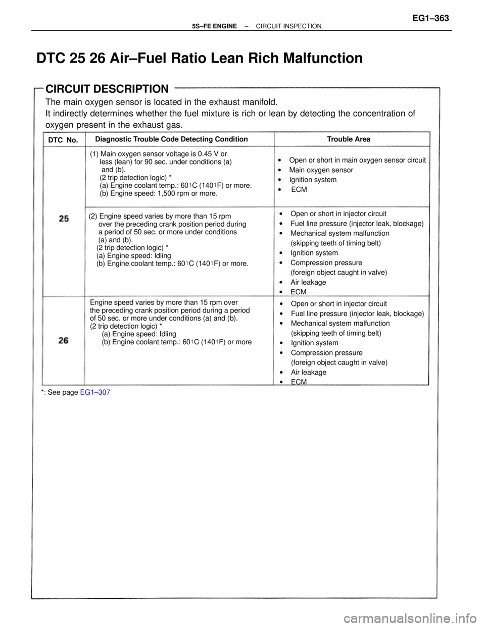
CIRCUIT DESCRIPTION
The main oxygen sensor is located in the exhaust manifold.
It indirectly determines whether the fuel mixture is rich or lean by detecting the concentration of
oxygen present in the exhaust gas.
Engine speed varies by more than 15 rpm over
the preceding crank position period during a period
of 50 sec. or more under conditions (a) and (b).
(2 trip detection logic) *
(a) Engine speed: Idling
(b) Engine coolant temp.: 60�C (140�F) or more (2) Engine speed varies by more than 15 rpm
over the preceding crank position period during
a period of 50 sec. or more under conditions
(a) and (b).
(2 trip detection logic) *
(a) Engine speed: Idling
(b) Engine coolant temp.: 60�C (140�F) or more.wOpen or short in injector circuit
wFuel line pressure (injector leak, blockage)
wMechanical system malfunction
(skipping teeth of timing belt)
wIgnition system
wCompression pressure
(foreign object caught in valve)
wAir leakage
wECM
wOpen or short in injector circuit
wFuel line pressure (injector leak, blockage)
wMechanical system malfunction
(skipping teeth of timing belt)
wIgnition system
wCompression pressure
(foreign object caught in valve)
wAir leakage
wECM (1) Main oxygen sensor voltage is 0.45 V or
less (lean) for 90 sec. under conditions (a)
and (b).
(2 trip detection logic) *
(a) Engine coolant temp.: 60�C (140�F) or more.
(b) Engine speed: 1,500 rpm or more.wOpen or short in main oxygen sensor circuit
wMain oxygen sensor
wIgnition system
w ECM Diagnostic Trouble Code Detecting Condition
*: See page EG1±307Trouble Area
DTC 25 26 Air±Fuel Ratio Lean Rich Malfunction
DTC No.
± 5S±FE ENGINECIRCUIT INSPECTIONEG1±363
Page 603 of 4770
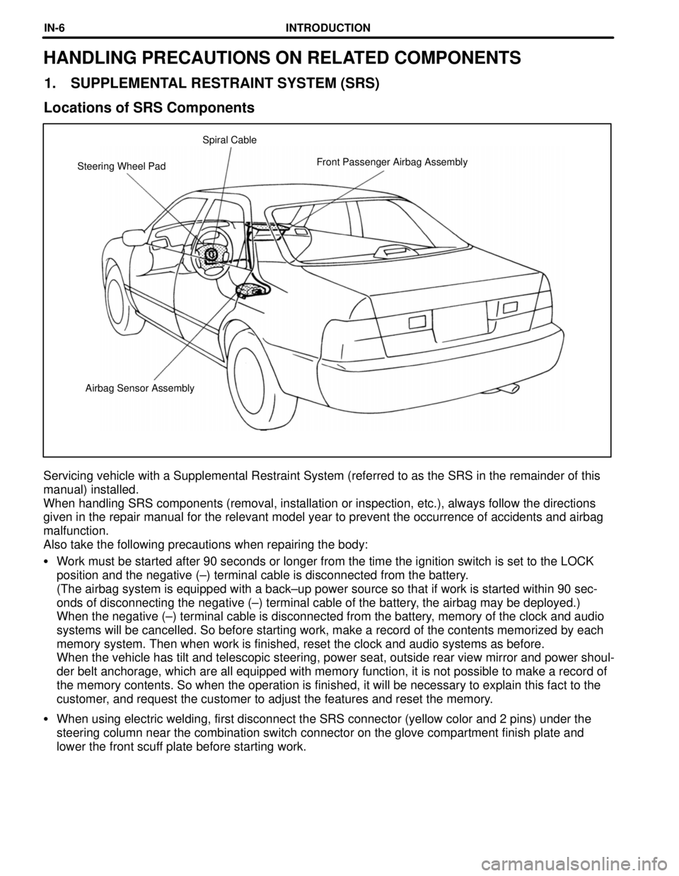
Airbag Sensor Assembly Steering Wheel PadFront Passenger Airbag Assembly Spiral Cable
HANDLING PRECAUTIONS ON RELATED COMPONENTS
1. SUPPLEMENTAL RESTRAINT SYSTEM (SRS)
Locations of SRS Components
Servicing vehicle with a Supplemental Restraint System (referred to as the SRS in the remainder of this
manual) installed.
When handling SRS components (removal, installation or inspection, etc.), always follow the directions
given in the repair manual for the relevant model year to prevent the occurrence of accidents and airbag
malfunction.
Also take the following precautions when repairing the body:
�Work must be started after 90 seconds or longer from the time the ignition switch is set to the LOCK
position and the negative (±) terminal cable is disconnected from the battery.
(The airbag system is equipped with a back±up power source so that if work is started within 90 sec-
onds of disconnecting the negative (±) terminal cable of the battery, the airbag may be deployed.)
When the negative (±) terminal cable is disconnected from the battery, memory of the clock and audio
systems will be cancelled. So before starting work, make a record of the contents memorized by each
memory system. Then when work is finished, reset the clock and audio systems as before.
When the vehicle has tilt and telescopic steering, power seat, outside rear view mirror and power shoul-
der belt anchorage, which are all equipped with memory function, it is not possible to make a record of
the memory contents. So when the operation is finished, it will be necessary to explain this fact to the
customer, and request the customer to adjust the features and reset the memory.
�When using electric welding, first disconnect the SRS connector (yellow color and 2 pins) under the
steering column near the combination switch connector on the glove compartment finish plate and
lower the front scuff plate before starting work.
INTRODUCTIONIN-6
Page 1113 of 4770

SCHEDULED MAINTENANCE LOGS21 Brake Linings/Drums and Brake Pads/Discs
Check the brake linings (shoes) and drums for scoring, burning,
fluid leakage, broken parts and excessive wear. Check the pads for
excessive wear and the discs for runout, excessive wear and fluid
leakage. A qualified technician should perform these inspections.
Charcoal Canister (CA, MA and NY vehicles)
Check for internal damage and clogging. If necessary, clean
with compressed air or replace. A qualified technician should
perform these operations.
Differential Oil
Inspect each component for signs of leakage. If you discover any
leakage, have it repaired by a qualified technician immediately.
Drive Belts
Inspect for cracks, excessive wear and oiliness. Check the belt ten-
sion and adjust if necessary. Replace the belts if they are damaged.
Drive Shaft Boots
Check the drive shaft boots and clamps for cracks, deteriora-
tion and damage. Replace any damaged parts and, if necessary,
repack the grease. Selected models also require periodic inspec-
tion of the flange bolts for proper torque. A qualified technician
should perform these operations.
Engine Air Filter
Check for damage, excessive wear and oiliness. Replace if necessary.
Engine Coolant
Drain and flush the cooling system and refill with an ethylene-
glycol type coolant. A qualified technician should perform
this operation.
Engine Oil and Oil Filter
Change the oil filter and replace the engine oil with API SH,
Energy- Conserving II multigrade or ILSAC multigrade oil.
For recommended viscosity, refer to your
Owner’s Manual.
Explanation of Maintenance Items
Page 1538 of 4770
CH0086
Correct Wrong
AC0LM±02
N17028
Generator
Crankshaft Pulley
Compressor
N01881
DENSOBorroughs AC±16
± AIR CONDITIONINGDRIVE BELT
2498 Author�: Date�:
DRIVE BELT
ON±VEHICLE INSPECTION
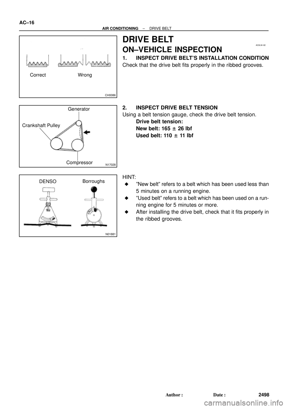
1. INSPECT DRIVE BELT'S INSTALLATION CONDITION
Check that the drive belt fits properly in the ribbed grooves.
2. INSPECT DRIVE BELT TENSION
Using a belt tension gauge, check the drive belt tension.
Drive belt tension:
New belt: 165 ± 26 lbf
Used belt: 110 ± 11 lbf
HINT:
�ºNew beltº refers to a belt which has been used less than
5 minutes on a running engine.
�ºUsed beltº refers to a belt which has been used on a run-
ning engine for 5 minutes or more.
�After installing the drive belt, check that it fits properly in
the ribbed grooves.
Page 1962 of 4770
BO0KU±01
± BODYSRS AIRBAG
BO±3
2351 Author�: Date�:
SRS AIRBAG
PRECAUTION
The CAMRY is equipped with SRS (Supplemental Restraint System) such as the driver airbag, front passen-
ger airbag, side airbag and seat belt pretensioner. Failure to carry out service operation in the correct se-
quence could cause the SRS to unexpectedly deploy during servicing, possibly leading to a serious acci-
dent. Before servicing (including removal or installation of parts, inspection or replacement), be sure to read
the precautionary notices in the RS section.