Page 1935 of 4770
VALVE BODY ASSEMBLY
AX±7
1927 Author�: Date�:
VALVE BODY ASSEMBLY
ON±VEHICLE REPAIR
1. DRAIN ATF
Using a hexagon wrench,")
AX03Q±02
AT3785
AT0103
D01019
Q05728
Connector
± AUTOMATIC TRANSAXLE (A541E)VALVE BODY ASSEMBLY
AX±7
1927 Author�: Date�:
VALVE BODY ASSEMBLY
ON±VEHICLE REPAIR
1. DRAIN ATF
Using a hexagon wrench, remove the drain plug and fluid into
the suitable container.
2. REMOVE OIL PAN AND GASKET
NOTICE:
Some fluid will remain in the oil pan.
Remove oil pan bolts, and carefully remove the pan assembly.
Discard the gasket.
3. EXAMINE PARTICLES IN PAN
Remove the magnets and use them to collect any steel chips.
Look at the chips and particles in the pan and magnet carefully
to anticipate what type of wear you will find in the transaxle.
�Steel (magnetic): bearing, gear and plate wear
�Brass (non±magnetic): bushing wear
4. REMOVE OIL STRAINER AND APPLY PIPE BRACKET
(a) Remove the 3 bolts and oil strainer.
NOTICE:
Be careful as oil will come out of the strainer when it is re-
moved.
(b) Remove the 3 bolts and apply pipe bracket.
5. REMOVE OIL PIPES
Pry up both pipe ends with a large screwdriver and remove the
5 pipes.
6. DISCONNECT SOLENOID CONNECTORS
Page 1937 of 4770
OR0038
Q05643
Q05657
Q05402
Q05657
± AUTOMATIC TRANSAXLE (A541E)VALVE BODY ASSEMBLY
AX±9
1929 Author�: Date�:
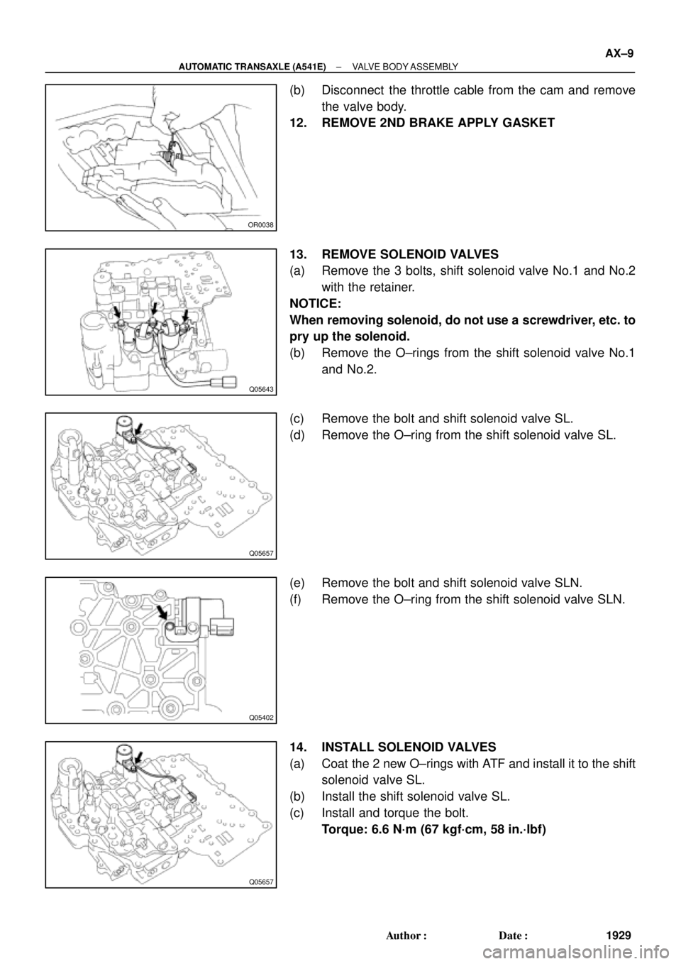
(b) Disconnect the throttle cable from the cam and remove
the valve body.
12. REMOVE 2ND BRAKE APPLY GASKET
13. REMOVE SOLENOID VALVES
(a) Remove the 3 bolts, shift solenoid valve No.1 and No.2
with the retainer.
NOTICE:
When removing solenoid, do not use a screwdriver, etc. to
pry up the solenoid.
(b) Remove the O±rings from the shift solenoid valve No.1
and No.2.
(c) Remove the bolt and shift solenoid valve SL.
(d) Remove the O±ring from the shift solenoid valve SL.
(e) Remove the bolt and shift solenoid valve SLN.
(f) Remove the O±ring from the shift solenoid valve SLN.
14. INSTALL SOLENOID VALVES
(a) Coat the 2 new O±rings with ATF and install it to the shift
solenoid valve SL.
(b) Install the shift solenoid valve SL.
(c) Install and torque the bolt.
Torque: 6.6 N´m (67 kgf´cm, 58 in.´lbf)
Page 1938 of 4770
VALVE BODY ASSEMBLY
1930 Author�: Date�:
(d) Coat the 2 new O±rings with ATF and install it to the shift
solenoid")
Q05402
Q05643
OR0038
D01023
A
C
CB
C
DD
D01058
AX±10
± AUTOMATIC TRANSAXLE (A541E)VALVE BODY ASSEMBLY
1930 Author�: Date�:
(d) Coat the 2 new O±rings with ATF and install it to the shift
solenoid valve SLN.
(e) Install the shift solenoid valve SLN.
(f) Install and torque the bolt.
Torque: 6.6 N´m (67 kgf´cm, 58 in.´lbf)
(g) Coat the 2 new O±rings with ATF and install it to the shift
solenoid valve No.1 and No.2.
(h) Install the No.1 and No.2 solenoids.
(i) Install and torque the 3 bolts.
Torque: 6.6 N´m (67 kgf´cm, 58 in.´lbf)
15. PLACE NEW 2ND BRAKE APPLY GASKET
16. INSTALL VALVE BODY TO TRANSAXLE CASE
(a) While holding the cam down with your hand, slip the cable
end into the slot.
(b) Lower the valve body into place.
NOTICE:
Be careful not to entangle the solenoid wire.
(c) Install and tighten the 9 bolts.
HINT:
Hand tighten the 9 bolts first, then torque with a torque wrench.
Bolt length:
Bolt A: 30 mm (1.181 in.)
Bolt B: 43 mm (1.693 in.)
Bolt C: 48 mm (1.890 in.)
Bolt D: 52 mm (2.047 in.)
Torque: 11 N´m (110 kgf´cm, 8 ft´lbf)
17. INSTALL B
3 APPLY PIPE
NOTICE:
Be careful not to bend or damage the pipe.
Page 1939 of 4770

BAmm (in.)
Q05728
Connector
± AUTOMATIC TRANSAXLE (A541E)VALVE BODY ASSEMBLY
AX±11
1931 Author�: Date�:
18. INSTALL CONNECTOR CLAMP AND PIPE RETAINER
(a) Ins")
D01059
A
B
D01021
B
B
A
Z19257
30
(1.18)
BAmm (in.)
Q05728
Connector
± AUTOMATIC TRANSAXLE (A541E)VALVE BODY ASSEMBLY
AX±11
1931 Author�: Date�:
18. INSTALL CONNECTOR CLAMP AND PIPE RETAINER
(a) Install the connector clamp and pipe retainer.
(b) Install and torque the 2 bolts.
Bolt length:
Bolt A: 48 mm (1.890 in.)
Bolt B: 39 mm (1.535 in.)
Torque: 11 N´m (110 kgf´cm, 8 ft´lbf)
19. INSTALL MANUAL VALVE BODY
(a) Align the manual valve with the pin on the manual shaft
lever.
(b) Lower the manual valve body into place.
(c) Hand tighten the 5 bolts first. Then, tighten them with a
torque wrench.
Bolt length:
Bolt A: 22 mm (0.866 in.)
Bolt B: 37 mm (1.457 in.)
Torque: 11 N´m (110 kgf´cm, 8 ft´lbf)
20. INSTALL DETENT SPRING AND OIL PIPE
(a) Place the detent springs on the manual valve body and
hand tighten the 2 bolts first. Then, tighten them with a
torque wrench.
Bolt length:
Bolt A: 14 mm (0.551 in.)
Bolt B: 37 mm (1.457 in.)
Torque: 11 N´m (110 kgf´cm, 8 ft´lbf)
(b) Check that the manual valve lever is touching the center
of the detent spring tip roller.
(c) Using a plastic hammer, install the pipe into the position.
NOTICE:
Be careful not to bend or damage the pipe.
(d) Install and torque the bolt.
Torque: 10 N´m (100 kgf´cm, 7 ft´lbf)
21. CONNECT SOLENOID CONNECTORS
22. INSTALL OIL PIPES
Using a plastic hammer, install the pipes into the positions.
NOTICE:
Be careful not to bend or damage the pipes.
Page 1944 of 4770
AX03T±01
D01026
Key Interlock Solenoid
Shift Lock Override ButtonShift Lock Override Cover
Stop Light Switch
Shift Lock Control Unit Assembly
AX±16
± AUTOMATIC TRANSAXLE (A541E)SHIFT LOCK SYSTEM (TMC Made)
1936 Author�: Date�:
SHIFT LOCK SYSTEM (TMC Made)
LOCATION
Page 1945 of 4770
 5 (IG)
4 (KLS+)
3 (E)
2 (STP)
Wire Harness Side
Q09456
1 (KLS+)
2 (E)
Q09457
1 (KLS+)
2 (E)
(±) (+)
± AUTOMATIC TRANSAXLE (A541E)SHIFT LOCK SYSTEM (TMC Made)
AX±17
1937 Aut")
AX03U±02
Q09455
1 (ACC) 5 (IG)
4 (KLS+)
3 (E)
2 (STP)
Wire Harness Side
Q09456
1 (KLS+)
2 (E)
Q09457
1 (KLS+)
2 (E)
(±) (+)
± AUTOMATIC TRANSAXLE (A541E)SHIFT LOCK SYSTEM (TMC Made)
AX±17
1937 Author�: Date�:
INSPECTION
1. INSPECT SHIFT LOCK CONTROL UNIT ASSEMBLY
Using a voltmeter, measure the voltage at each terminal.
HINT:
Do not disconnect the shift lock control unit assembly connec-
tor.
TerminalMeasuring ConditionVoltage (V)
1 ± 3 (ACC ± E)Ignition switch ACC10 ± 14
5 ± 3 (IG ± E)Ignition switch ON10 ± 14
2 ± 3 (STP ± E)Depressing brake pedal10 ± 14
4 ± 3 (KLS+ ± E)
(1) Ignition switch ACC and P position
(2) Ignition switch ACC and except P position
(3) Ignition switch ACC and except P position (After approx. 1 second)0
7.5 ± 11
6 ± 9.5
2. INSPECT KEY INTERLOCK SOLENOID
(a) Disconnect the solenoid connector.
(b) Using an ohmmeter, measure resistance between termi-
nals.
Standard resistance: 12.5 ± 16.5 W
If resistance value is not as specified, replace the solenoid.
(c) Apply battery positive voltage between terminals. Check
that an operation noise can be heard from the solenoid.
If the solenoid does not operated, replace the solenoid.
Page 1946 of 4770
AX03V±01
D01027
Key Interlock Solenoid
Shift Lock Control ECU Shift Lock Override Cover
Shift Lock Control SwitchShift Lock Override Button Stop Light Switch
Shift Lock Solenoid
AX±18
± AUTOMATIC TRANSAXLE (A541E)SHIFT LOCK SYSTEM (TMMK Made)
1938 Author�: Date�:
SHIFT LOCK SYSTEM (TMMK Made)
LOCATION
Page 1947 of 4770

1 (P)
4 (KLS+) 3 (IG)
6 (STP)
5 (E)
BBack Side
Front Side A
4 (P2)
5 (SLS±)
3 (P1)
2 (SLS+)
Q09460
5 (SLS±)
2 (SLS+)
Q09461
5 (SLS±)
2 (SLS+)
± AUTOMATIC TRANSAXLE (A541E)")
AX03W±01
Q09459
1 (ACC)
1 (P)
4 (KLS+) 3 (IG)
6 (STP)
5 (E)
BBack Side
Front Side A
4 (P2)
5 (SLS±)
3 (P1)
2 (SLS+)
Q09460
5 (SLS±)
2 (SLS+)
Q09461
5 (SLS±)
2 (SLS+)
± AUTOMATIC TRANSAXLE (A541E)SHIFT LOCK SYSTEM (TMMK Made)
AX±19
1939 Author�: Date�:
INSPECTION
1. INSPECT SHIFT LOCK CONTROL ECU
Using a voltmeter, measure voltage at each terminal.
HINT:
Do not disconnect the ECU connector.
TerminalMeasuring ConditionVoltage (V)
A, 1 ± A, 5 (ACC ± E)Ignition switch ACC10 ± 14
A, 3 ± A, 5 (IG ± E)Ignition switch ON10 ± 14
A, 6 ± A, 5 (STP ± E)Depressing brake pedal10 ± 14
A, 4 ± A, 5 (KLS+ ± E)
(1) Ignition switch ACC and P position
(2) Ignition switch ACC and except P position
(3) Ignition switch ACC and except P position (After approx. 1 second)0
7.5 ± 11
6 ± 9.5
B, 2 ± B, 5 (SLS+ ± SLS±)
(1) Ignition switch ON and P position
(2) Depress brake pedal
(3) Except P position0
8 ± 13.5
0
B, 3 ± B, 1 (P1 ± P)(1) Ignition switch ON, P position and depress brake pedal
(2) Shift except P position under conditions above0
9 ± 13.5
B, 4 ± B, 1 (P2 ± P)(1) Ignition switch ACC, P position
(2) Shift except P position under conditions above9 ± 13.5
0
2. INSPECT SHIFT LOCK SOLENOID
(a) Disconnect the solenoid connector.
(b) Using an ohmmeter, measure resistance between termi-
nals.
Standard resistance: 29 ± 35 W
If resistance value is not as specified, replace the solenoid.
(c) Apply battery positive voltage between terminals. Check
that operation.
If the solenoid does not operated, replace the solenoid noise
can be heard from the solenoid.
SHIFT LOCK SYSTEM (T")
