Page 603 of 4770

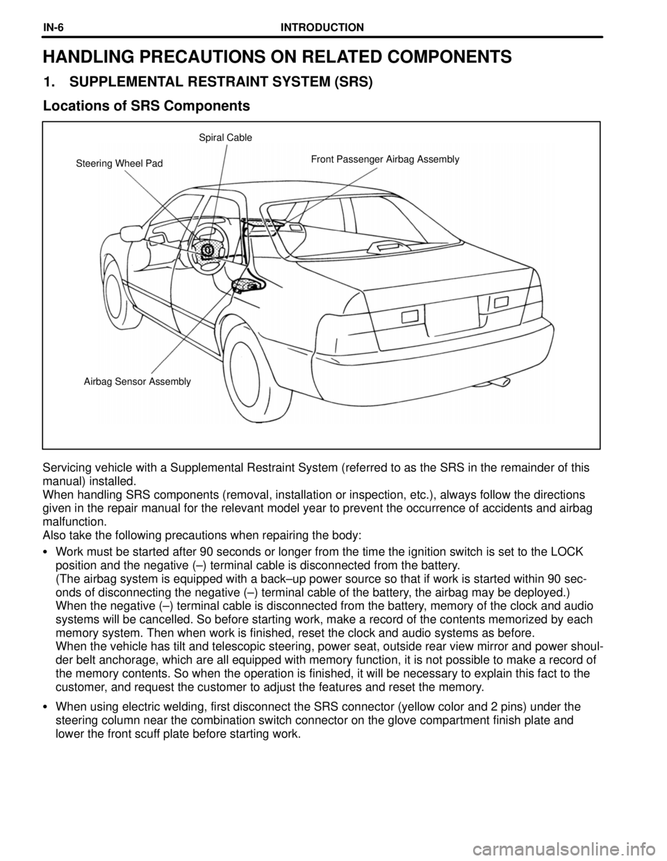
Airbag Sensor Assembly Steering Wheel PadFront Passenger Airbag Assembly Spiral Cable
HANDLING PRECAUTIONS ON RELATED COMPONENTS
1. SUPPLEMENTAL RESTRAINT SYSTEM (SRS)
Locations of SRS Components
Servicing vehicle with a Supplemental Restraint System (referred to as the SRS in the remainder of this
manual) installed.
When handling SRS components (removal, installation or inspection, etc.), always follow the directions
given in the repair manual for the relevant model year to prevent the occurrence of accidents and airbag
malfunction.
Also take the following precautions when repairing the body:
�Work must be started after 90 seconds or longer from the time the ignition switch is set to the LOCK
position and the negative (±) terminal cable is disconnected from the battery.
(The airbag system is equipped with a back±up power source so that if work is started within 90 sec-
onds of disconnecting the negative (±) terminal cable of the battery, the airbag may be deployed.)
When the negative (±) terminal cable is disconnected from the battery, memory of the clock and audio
systems will be cancelled. So before starting work, make a record of the contents memorized by each
memory system. Then when work is finished, reset the clock and audio systems as before.
When the vehicle has tilt and telescopic steering, power seat, outside rear view mirror and power shoul-
der belt anchorage, which are all equipped with memory function, it is not possible to make a record of
the memory contents. So when the operation is finished, it will be necessary to explain this fact to the
customer, and request the customer to adjust the features and reset the memory.
�When using electric welding, first disconnect the SRS connector (yellow color and 2 pins) under the
steering column near the combination switch connector on the glove compartment finish plate and
lower the front scuff plate before starting work.
INTRODUCTIONIN-6
Page 711 of 4770

CAMRY ± OUTLINE OF NEW FEATURES
CAMRY
2
OUTLINE OF NEW FEATURES
The Camry is a high-quality family sedan with advanced technology and sporty performance. The following
changes are made for the 1998 model year.
1. Model Line-Up
�The SXV20L-AEPNKK and MCV20L-A (C) EPGKK models have been added.
�The MCV20L-CEPNKK model has been discontinued.
2. Interior Equipment
An extensible assist grip has been newly provided for the front passenger.
3. 5S-FE Engine
ORVR (On-Board Refueling Vapor Recovery) System has been adopted.
4. 1MZ-FE Engine
The 1MZ-FE engine with automatic transaxle on the California specification model uses the air-fuel ratio
sensor and the WU-TWC (Warm Up-Three-Way Catalytic Converters) to reduce exhaust emissions.
5. Body
�The cross section shape of the outside windshield moulding has been changed to reduce the wind noise.
�The front door window glass has been increased in thickness to reduce the amount of noise transmitted
from the outside of the vehicle.
�Front seat belt with pretensioner and force limiter has been adopted.
6. Engine Immobiliser System
An engine immobiliser system has been newly provided to help improve the vehicle's theft prevention perfor-
mance.
7. Theft Deterrent System
�The starter cutoff function has been discontinued along with the adoption of the engine immobiliser sys-
tem.
�The illumination pattern of the indicator light which indicates the condition of the system has been
changed.
Page 716 of 4770

CAMRY ± NEW FEATURES7
�1MZ-FE ENGINE
1. Description
On the California specification automatic transaxle model, the 1MZ-FE engine has adopted the air-fuel ratio
sensor and the WU-TWC (Warm Up-Three-Way Catalytic Converter) to reduce exhaust emissions.
2. Engine Specifications
1MZ-FE Engine
Item'98 Model'97 Model
No. of Cyls. & Arrangement6-Cylinder, V Type�
Valve Mechanism24-Valve, DOHC,
Belt & Gear Drive�
Combustion ChamberPentroof Type�
ManifoldsCross-Flow�
Fuel SystemSFI�
Displacement cm3 (cu. in.)2995 (182.7)�
Bore x Stroke mm (in.)87.5 x 83.0 (3.44 x 3.27)�
Compression Ratio10.5 : 1�
Max. Output [SAE-NET]
145 kW@5200 rpm
(194HP@5200 rpm),
143 kW@5200 rpm
(192 HP@5200 rpm)*
145 kW@5200 rpm
(194HP@5200 rpm)
Max. Torque [SAE-NET]
283 N.m@4400 rpm
(209 ft
.lbf@4400 rpm),
281 N
.m@4400 rpm
(207 ft
.lbf@4400 rpm)*
283 N.m@4400 rpm
(209 ft
.lbf@4400 rpm)
IntakeOpen4� BTDC�
Valve
IntakeClose44� ABDC�Valve
Timing
ExhaustOpen46� BBDC�g
ExhaustClose2� AT D C�
Fuel Octane Number RON91 or Higher�
Oil GradeAPI SH EC-II,
SJ EC or ILSACAPI SH EC II or ILSAC
Premium unleaded gasoline (96RON) is used for the above specifications.
*: California Specification Automatic Transaxle Model.
Page 724 of 4770

CAMRY ± NEW FEATURES
150NF105 150NF104Inactive Activated Wire
PulleyDrum
Piston
Cylinder
15
�SEAT BELT
1. General
�The front seats are provided with an electrical sensing type seat belt pretensioner and a seat belt force limiter.
In the beginning of a collision, the seat belt pretensioner instantly pulls up the seat belt thus providing the
excellent belt's effectiveness in restraining the occupant.
When the impact of a collision causes the tension of the seat belt applied to the occupant to reach a predeter-
mined level, the force limiter restrains the tension, thus controlling the force applied to the occupant's chest
area.
�In accordance with the ignition signal from the airbag sensor assembly, the seat belt pretensioner activates
simultaneously with the deployment of the
SRS airbags for the driver and front passenger.
2. Seat Belt Pretensioner
Construction and Operation
The seat belt pretensioner consists of the pretensioner mechanism and retracting mechanism.
The pretensioner mechanism consists of a gas generator, piston, wire, drum and etc.
If the airbag sensor is turned on by deceleration due to frontal collision, electric current then ignites the gas
generator located in the pretensioner. As a result, the gas generator emits gas in an extremely short time and
pushes the piston. Since the cable is attached to the piston, the piston will pull on the cable causing the drum
to grab onto the shaft. The shaft will then move in the retracting direction pulling up the belt for a predeter-
mined length.
Page 725 of 4770
CAMRY ± NEW FEATURES
150NF107 150NF106150NF108Inactive Activated End Shaft (Fix) Spool
Seat BeltForce
Limiter
Plate
Shaft (Fix)Contact
16
3. Seat Belt Force Limiter
Construction and Operation
Seat belt force limiter consists of the force limiter plate, spool, shaft and etc.
When a further movement of the occupant applies a force that exceeds the specified load, the force limiter
plate begins to deform, and the spool rotates along with the movement of the belt allowing the belt to be
pulled out. At this time, the force limiter plate deforms as if wrapping around the shaft along with the rota-
tion of the spool, and acts as a resistance force against the pullling of the belt.
When the spool makes 1-1 / 4 turns, the plate makes one complete turn around the shaft. As the plates them-
selves come in contact, the spool will not be able to rotate further. As a result, the force limiter completes
its activation.
Page 771 of 4770
'99camry U
5
Indicator symbols on the instrument panel
Brake system warning light*
1
Seat belt reminder light*
1
Discharge warning light*
1
Malfunction indicator lamp*
1
Low oil pressure warning light*
1
Anti-lock brake system warning light*
1
(type A)
(type B)
Open door warning light*
1
Rear light failure warning light*
1
(type A)
(type B)
SRS airbag warning light*
1
Low windshield washer fluid level warning light*
1
Page 779 of 4770
'99camry U
13
LOCKING AND UNLOCKING WITH POW-
ER DOOR LOCK SWITCH
Push the switch.
To lock: Push the switch on the front side.
To unlock: Push the switch on the rear
side.
All the doors lock or unlock simultaneous-
ly.
REAR DOOR CHILD±PROTECTORS
Move the lock lever to the ºLOCKº
position as shown on the label.
This feature allows you to lock a rear
door so it can be opened from the outside
only, not from inside. We recommend us-
ing this feature whenever small children
are in the vehicle.
CAUTION
Before driving, be sure that the doors
are closed and locked, especially
when small children are in the ve-
hicle. Along with the proper use of
seat belts, locking the doors helps
prevent the driver and passengers
from being thrown out from the ve-
hicle during an accident. It also helps
prevent the doors from being opened
unintentionally.
Page 793 of 4770

'99camry U
27
Part 1
OPERATION OF
INSTRUMENTS AND
CONTROLSÐ
Chapter 1±3
Seats, Seat belts,
Steering wheel and
Mirrors
�Seats
�Front seats
�Fold±down rear seat
�Head restraints
�Seat belts
�SRS driver and front passenger
airbags
�SRS side airbags
�Child restraint
�Tilt steering wheel
�Outside rear view mirrors�Anti±glare inside rear view
mirror
�Sun visors
Seats
While the vehicle is being driven, all ve-
hicle occupants should have the seatback
upright, sit well back in the seat and prop-
erly wear the seat belts provided.
CAUTION
�Do not drive the vehicle unless the
occupants are properly seated. Do
not allow sitting on top of a
folded±down seatback, or in the
luggage compartment. Persons not
properly seated and not properly re-
strained by seat belts can be se-
verely injured in the event of emer-
gency braking or a collision.
�During driving, do not allow pas-
sengers to stand up or move
around between seats. Severe inju-
ries can occur in the event of emer-
gency braking or a collision.