Page 1180 of 4770

G
Position of Parts in Instrument Panel
J 1 Junction Connector
J 2 Junction Connector
J 3 Junction Connector
J 4 Junction Connector
J 5 Junction Connector
J 6 Junction Connector
J 7 Junction Connector
J 8 Junction Connector
J 9 Junction Connector
J 10 Junction Connector
J 11 Junction Connector
J 12 Junction Connector
J 13 Junction Connector
J 14 Junction Connector
J 15 Junction Connector
J 16 Junction Connector
J 17 Junction Connector
J 18 Junction Connector
J 19 Junction Connector
J 20 Junction Connector
J 21 Junction Connector
J 22 Junction Connector
J 23 Junction Connector
J 24 Junction Connector
J 25 Junction Connector
J 26 Junction Connector
J 27 Junction Connector
J 28 Junction Connector
J 29 Junction Connector
J 30 Junction Connector
J 31 Junction Connector
J 32 Junction Connector
J 33 Junction ConnectorJ 34 Junction Connector
J 35 Junction Connector
J 36 Junction Connector
J 37 Junction Connector
K 3 Key Interlock Solenoid
O 2 O/D Main SW and A/T Shift Lever Illumination
P 3 Parking Brake SW
P 4 Power Outlet
R 2 Radio and Player
R 3 Radio and Player
R 4 Radio and Player
R 5 Rear Window Defogger SW
R 6 Remote Control Mirror SW
R 7 Rheostat
S 3 Shift Lock ECU
S 4 Stereo Component Amplifier
S 5 Stereo Component Amplifier
S 6 Stop Light SW
T 3 Theft Deterrent ECU
T 4 Theft Deterrent ECU
T 5 Traction Off SW
T 6 Turn Signal Flasher
T 7 Transponder Key Amplifier
U 1 Unlock Warning SW
W 6 Wireless Door Lock ECU
Page 1181 of 4770

G ELECTRICAL WIRING ROUTING
Position of Parts in Body
A 25 ABS Speed Sensor Rear LH
A 26 ABS Speed Sensor Rear RH
A 27 Auto Antenna Motor and Relay
B 6 Buckle SW LH
C 16 Condenser
D 12 Door Courtesy SW Front LH
D 13 Door Courtesy SW Front RH
D 14 Door Courtesy SW Rear LH
D 15 Door Courtesy SW Rear RH
D 16 Door Key Lock and Unlock SW Front LH
D 17 Door Key Lock and Unlock SW Front RH
D 18 Door Lock Control SW RH
D 19 Door Lock Motor and Door Unlock Detection SW Front LH
D 20 Door Lock Motor and Door Unlock Detection SW Front RH
D 21 Door Lock Motor and Door Unlock Detection SW Rear LH
D 22 Door Lock Motor and Door Unlock Detection SW Rear RHF 10 Front Door Speaker LH
F 11 Front Door Speaker RH
F 12 Front Tweeter (Speaker) LH
F 13 Front Tweeter (Speaker) RH
F 14 Fuel Pump and Sender
H 10 High Mounted Stop Light
I 19 Interior Light
J 38 Junction Connector
J 39 Junction Connector
J 40 Junction Connector
L 1 License Plate Light LH
L 2 License Plate Light RH
L 3 Light Failure Sensor
L 4 Luggage Compartment Key Unlock SW
L 5 Luggage Compartment Light
L 6 Luggage Compartment Light SW
Page 1182 of 4770
G
Position of Parts in Body
M 3 Moon Roof Control SW and Relay
M 4 Moon Roof Motor and Limit SW
N 2 Noise Filter (Rear Window Defogger)
P 5 Personal Light
P 6 Power Window Control SW Front RH
P 7 Power Window Control SW Rear LH
P 8 Power Window Control SW Rear RH
P 9 Power Window Master SW and Door Lock Control SW LH
P 10 Power Window Motor Front LH
P 11 Power Window Motor Front RH
P 12 Power Window Motor Rear LH
P 13 Power Window Motor Rear RH
P 24 Pretensioner LH
P 25 Pretensioner RHR 8 Rear Combination Light LH
R 9 Rear Combination Light LH
R 10 Rear Combination Light RH
R 11 Rear Combination Light RH
R 12 Rear Speaker LH
R 13 Rear Speaker RH
R 14 Rear Window Defogger
R 15 Rear Window Defogger
R 16 Remote Control Mirror LH
R 17 Remote Control Mirror RH
S 7 Side Airbag Sensor LH
S 8 Side Airbag Sensor RH
V 1 Vapor Pressure Sensor
V 7 VSV (Vapor Pressure Sensor)
V 8 Vanity Light LH
V 9 Vanity Light RH
Page 1257 of 4770
LIGHT AUTO TURN OFF
A 1C 1F1F2 E 37. 5A
DOME FROM POWER SOURCE SYSTEM (
SEE PAGE 50)
2J 12
1W 1 23 15
1C 6 1B 4
C 2
IG 1J 71J8
OFF
TAI L
HEAD
LIGHT
CONTROL SW
C 1C4
11S 7
16 A
6 10
AA A71 AB±G
B±R
B±RB
B±R
G± R G±R
R R±GR±Y W±BW±B
W±B
G
JUNCTION
CONNECTOR J11
JUNCTION
CONNECTOR J 7DOOR COURTESY SW
FRONT L H D12 JUNCTION
CONNECTOR J 2
COMBINATION SW C13 FUSIBLE LINK BLOCK
INTEGRATION RELAY B
TAILLIGHT
RELAY10A
GAU GE
BATTERY13 14
FL MA IN
3. 0L* 3 : TMC MADE
* 4 : TMMK MADE
100A
ALT
C F 4 A , F 6 F, F 9
I17 C * 1 : W/O DAYTIME RUNNING LIGHT
* 2 : W/ DAY TIME RUNNING LIGHT40A
MAIN
2 12B 3
32 41
2K 8
C 3B
B BB
H
R±BR
H±LP
R±B R±BR±B
JUNCTION
CONNECTOR J 1
HEAD
RELAY
JUNCTION
CONNECTOR J3 2
(
*1)
(
*2)
(
*2)
(
*2)
(
*1)B 19(
*4) A 6(
*3)
B 2(
*4) A 5(
*3)
B D 6 , A
DAYTIME RUNNING
LIGHT RELAY (
MAIN)
TA ILB 16
T
B 17
G± Y
G±R
(
*2 *4)
(
*2 *4)(
EXCEPT * 2 * 4)
Page 1269 of 4770
INTERIOR LIGHT
2 1
12
OFF
ON DOOR
2 1 7. 5A
DOME2 1
1
1V 32J 12
1F 32A 1
B 1 B 1
IG IE C 1
A 1
AR
R R W±B
R±W
R±W R R B
W± B W± BW±B B±G B
RR W±B W± B
R±Y
SHORT
PIN
VANITY LIGHT LH
I NTERI OR L I GHT
LUGGAGE COMPARTMENT LIGHTV 8
L 5I19
B 3 : * 1
B 2 : * 2(
W/ FADE OU T)
(
W/O FADE OUT)
FL MAIN
3. 0W
BATTERY
JUNCTION
CONNECTOR
LUGGAGE COMPARTMENT
LIGHT SW
J11
L 6(
*1) W± B
(
*1)
B 5 2 1
C16
CONDENSER R
LIGHT FAILURE SENSOR L 3
R
F 4
FUSIBLE LINK
BLOCKC A, F 6
P 5
PERSONAL LIGHT
1 21R
R
2 1VANITY LIGHT RH V 9
BM
W±B
Page 1271 of 4770

INTERIOR LIGHT
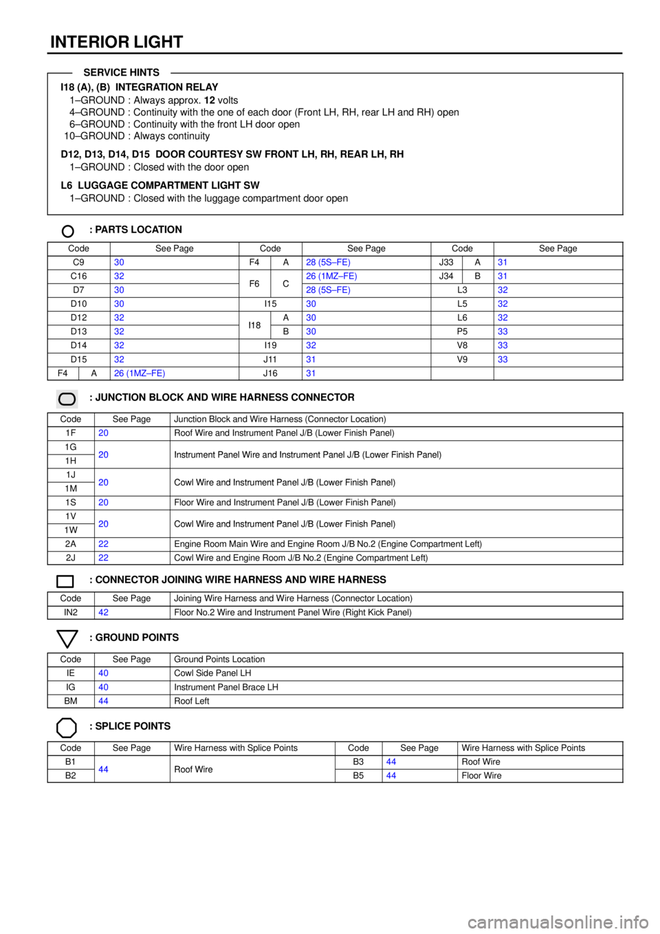
I18 (A), (B) INTEGRATION RELAY
1±GROUND : Always approx. 12 volts
4±GROUND : Continuity with the one of each door (Front LH, RH, rear LH and RH) open
6±GROUND : Continuity with the front LH door open
10±GROUND : Always continuity
D12, D13, D14, D15 DOOR COURTESY SW FRONT LH, RH, REAR LH, RH
1±GROUND : Closed with the door open
L6 LUGGAGE COMPARTMENT LIGHT SW
1±GROUND : Closed with the luggage compartment door open
: PARTS LOCATION
CodeSee PageCodeSee PageCodeSee Page
C930F4A28 (5S±FE)J33A31
C1632F6C26 (1MZ±FE)J34B31
D730F6C28 (5S±FE)L332
D1030I1530L532
D1232I18A30L632
D1332I18B30P533
D1432I1932V833
D1532J1131V933
F4A26 (1MZ±FE)J1631
: JUNCTION BLOCK AND WIRE HARNESS CONNECTOR
CodeSee PageJunction Block and Wire Harness (Connector Location)
1F20Roof Wire and Instrument Panel J/B (Lower Finish Panel)
1G20Instrument Panel Wire and Instrument Panel J/B (Lower Finish Panel)1H20Instrument Panel Wire and Instrument Panel J/B (Lower Finish Panel)
1J20Cowl Wire and Instrument Panel J/B (Lower Finish Panel)1M20Cowl Wire and Instrument Panel J/B (Lower Finish Panel)
1S20Floor Wire and Instrument Panel J/B (Lower Finish Panel)
1V20Cowl Wire and Instrument Panel J/B (Lower Finish Panel)1W20Cowl Wire and Instrument Panel J/B (Lower Finish Panel)
2A22Engine Room Main Wire and Engine Room J/B No.2 (Engine Compartment Left)
2J22Cowl Wire and Engine Room J/B No.2 (Engine Compartment Left)
: CONNECTOR JOINING WIRE HARNESS AND WIRE HARNESS
CodeSee PageJoining Wire Harness and Wire Harness (Connector Location)
IN242Floor No.2 Wire and Instrument Panel Wire (Right Kick Panel)
: GROUND POINTS
CodeSee PageGround Points Location
IE40Cowl Side Panel LH
IG40Instrument Panel Brace LH
BM44Roof Left
: SPLICE POINTS
CodeSee PageWire Harness with Splice PointsCodeSee PageWire Harness with Splice Points
B144Roof WireB344Roof Wire
B244Roof WireB544Floor Wire
SERVICE HINTS
Page 1294 of 4770

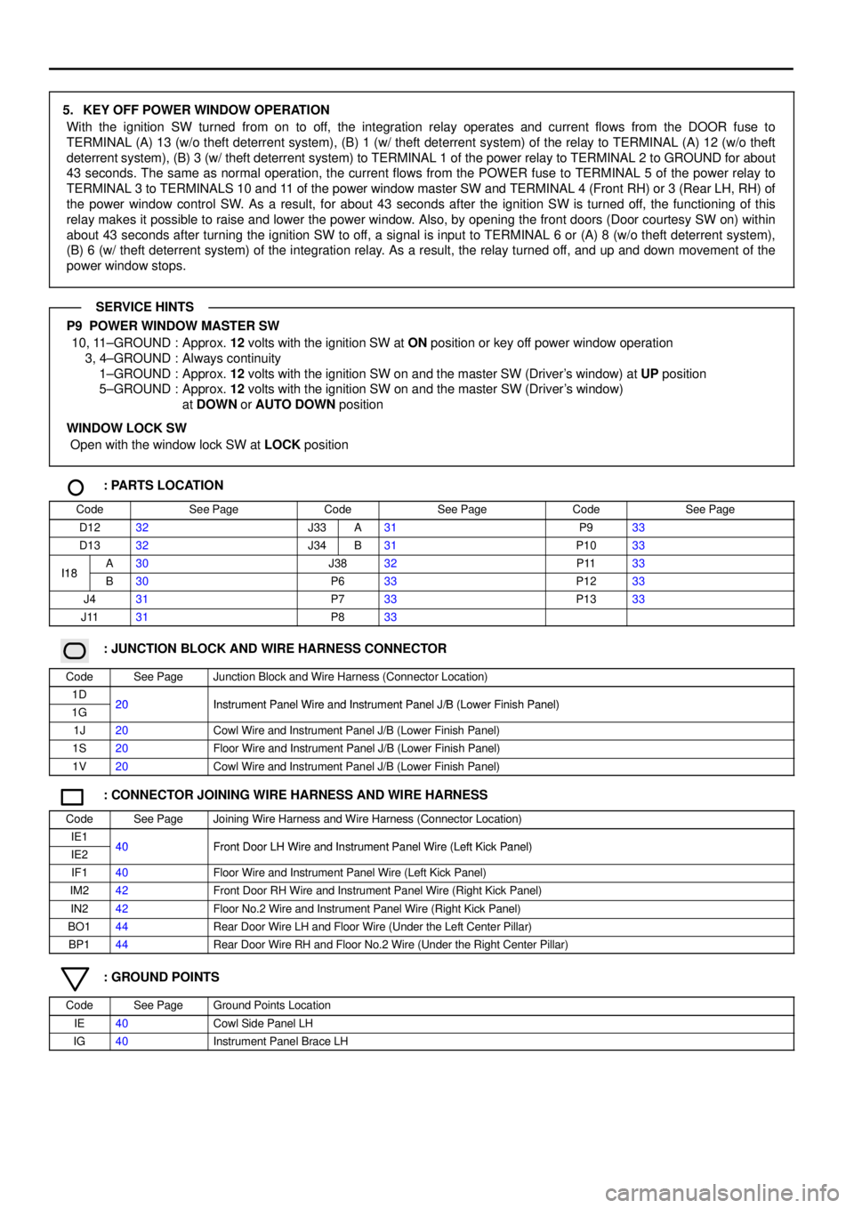
5. KEY OFF POWER WINDOW OPERATION
With the ignition SW turned from on to off, the integration relay operates and current flows from the DOOR fuse to
TERMINAL (A) 13 (w/o theft deterrent system), (B) 1 (w/ theft deterrent system) of the relay to TERMINAL (A) 12 (w/o theft
deterrent system), (B) 3 (w/ theft deterrent system) to TERMINAL 1 of the power relay to TERMINAL 2 to GROUND for about
43 seconds. The same as normal operation, the current flows from the POWER fuse to TERMINAL 5 of the power relay to
TERMINAL 3 to TERMINALS 10 and 11 of the power window master SW and TERMINAL 4 (Front RH) or 3 (Rear LH, RH) of
the power window control SW. As a result, for about 43 seconds after the ignition SW is turned off, the functioning of this
relay makes it possible to raise and lower the power window. Also, by opening the front doors (Door courtesy SW on) within
about 43 seconds after turning the ignition SW to off, a signal is input to TERMINAL 6 or (A) 8 (w/o theft deterrent system),
(B) 6 (w/ theft deterrent system) of the integration relay. As a result, the relay turned off, and up and down movement of the
power window stops.
P9 POWER WINDOW MASTER SW
10, 11±GROUND : Approx. 12 volts with the ignition SW at ON position or key off power window operation
3, 4±GROUND : Always continuity
1±GROUND : Approx. 12 volts with the ignition SW on and the master SW (Driver's window) at UP position
5±GROUND : Approx. 12 volts with the ignition SW on and the master SW (Driver's window)
at DOWN or AUTO DOWN position
WINDOW LOCK SW
Open with the window lock SW at LOCK position
: PARTS LOCATION
CodeSee PageCodeSee PageCodeSee Page
D1232J33A31P933
D1332J34B31P1033
I18A30J3832P1133I18B30P633P1233
J431P733P1333
J1131P833
: JUNCTION BLOCK AND WIRE HARNESS CONNECTOR
CodeSee PageJunction Block and Wire Harness (Connector Location)
1D20Instrument Panel Wire and Instrument Panel J/B (Lower Finish Panel)1G20Instrument Panel Wire and Instrument Panel J/B (Lower Finish Panel)
1J20Cowl Wire and Instrument Panel J/B (Lower Finish Panel)
1S20Floor Wire and Instrument Panel J/B (Lower Finish Panel)
1V20Cowl Wire and Instrument Panel J/B (Lower Finish Panel)
: CONNECTOR JOINING WIRE HARNESS AND WIRE HARNESS
CodeSee PageJoining Wire Harness and Wire Harness (Connector Location)
IE140Front Door LH Wire and Instrument Panel Wire (Left Kick Panel)IE240Front Door LH Wire and Instrument Panel Wire (Left Kick Panel)
IF140Floor Wire and Instrument Panel Wire (Left Kick Panel)
IM242Front Door RH Wire and Instrument Panel Wire (Right Kick Panel)
IN242Floor No.2 Wire and Instrument Panel Wire (Right Kick Panel)
BO144Rear Door Wire LH and Floor Wire (Under the Left Center Pillar)
BP144Rear Door Wire RH and Floor No.2 Wire (Under the Right Center Pillar)
: GROUND POINTS
CodeSee PageGround Points Location
IE40Cowl Side Panel LH
IG40Instrument Panel Brace LH
SERVICE HINTS
Page 1297 of 4770

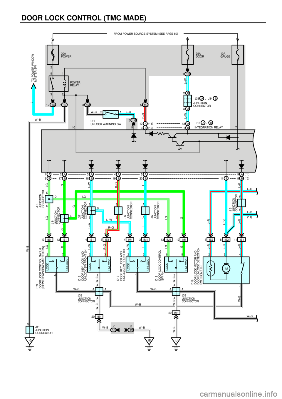
DOOR LOCK CONTROL (TMC MADE)
IGIE IJ 230A
POWER25A
DOOR FROM POWER SOURCE SYSTEM (
SEE PAGE 50)
1D 1
32 51
IE1 13 IE112 IE14IE13IM14IM13IM113 IM112 IE23IE28IE111
IE1 20IM1 20 1G 12 1J71G5
1G7
1V3
UNLOCK LOCK
4 27
UNLOCK LOCK
1 23
UNLOCK LOCK
1 23
UNLOCK LOCK
3 65
M B 1 B 3A A
A 1A2A3A4A5A 9 B C
A A1 A B B D
EF D
EBBA
AA
AA
AF D
EB
AA W±BL±R
L±B
W±B
W± B W± B LG
L±W
R±G
W±B
W±B
W±B W±B W±B
W± B L± RL±B L±RG LGL L±W R±G L±WG LG W±B
LG
GLG
G
L±W
R±G
L
LG
G L L±W
L±R L(
*2) L±R
L±R W±B W±B
L±WR±B
L±W L
W±B
4 3 2
TO POWER WINDOW
MASTER SWPOWER
RELAY
JUNCTION
CONNECTOR
INTEGRATION RELAY
JUNCTION
CONNECTOR JUNCTION
CONNECTOR J 6
J3 7 JUNCTION
CONNECTOR J3 7JUNCTION
CONNECTOR J 6
JUNCTION
CONNECTOR J 6
JUNCTION
CONNECTORJUNCTION
CONNECTOR
JUNCTION
CONNECTOR J11J38J39
DOOR LOCK MOTOR AND
DOOR UNLOCK DETECTION
SW FRONT LHDOOR LOCK CONTROL
SW RH DOOR KEY LOCK AND
UNLOCK SW FRONT RH DOOR KEY LOCK AND
UNLOCK SW FRONT LH DOOR LOCK CONTROL SW LH
[POWER WINDOW MASTER SW] P 9
D16
D17
D18
D19
JUNCTION
CONNECTOR J 6
1 2
1M 5 1M 3
W±B L±B
5 10UNLOCK WARNING SW U 110A
GAU GE
7 1
A 12 A13 (
*1)
(
*2)B ,
B 16 B17 B18 B19 B20B 5 B 11(
*1)
(
*2)
(
*1) B J33 A , J34
I18 A
G