Page 2208 of 4770
BE0AZ±05
Z19489
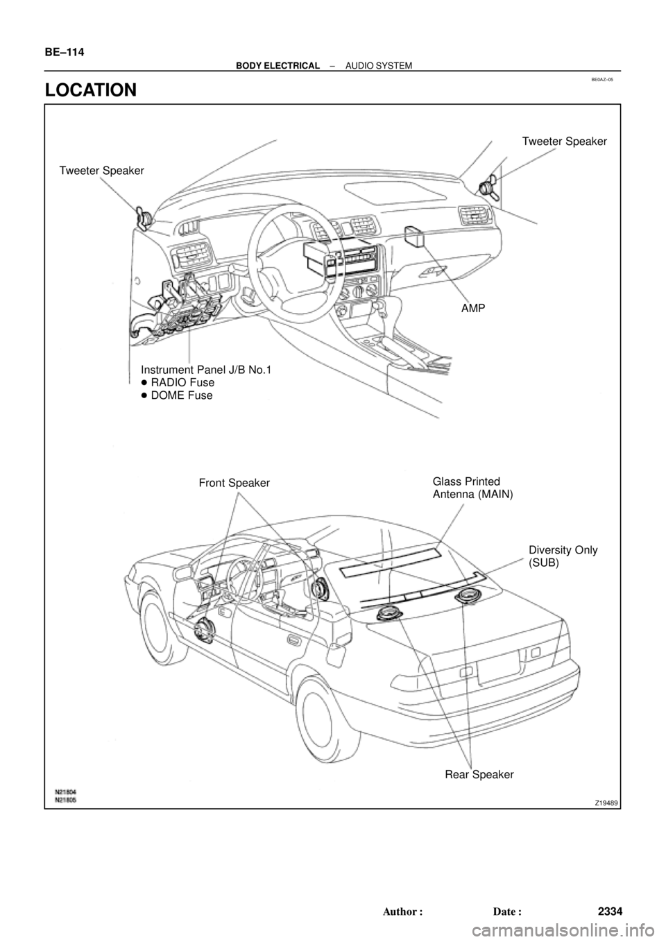
Tweeter SpeakerTweeter Speaker
AMP
Instrument Panel J/B No.1
� RADIO Fuse
� DOME Fuse
Front SpeakerGlass Printed
Antenna (MAIN)
Diversity Only
(SUB)
Rear Speaker BE±114
± BODY ELECTRICALAUDIO SYSTEM
2334 Author�: Date�:
LOCATION
Page 3622 of 4770
BO0L2±01
H01975
Door Lock
Cylinder
Outside Handle Front Door Belt Moulding
Door Glass
Door FrameFront Door Upper Moulding
Outside
Rear View
Mirror
Door Glass
Run
5.5 (55, 49 in.´lbf)
5.5 (55, 49 in.´lbf)
5.0 (50, 43 in.´lbf)�
Door Lock
23 (230, 17)
Window Regulator
8.0 (80, 69 in.´lbf)
Door Hinge
X6
7.5 (75, 66 in.´lbf)
Regulator
Motor
X3
31 (310, 22)
26 (260, 19)
8.0 (80, 71 in.´lbf)
30 (300, 22)
31 (310, 22)
Door
Check
Door Hinge
26 (260, 19)
Speaker
Power Window Switch Rear Lower
FrameFront Lower
FrameFront Window Upper
Garnish
Inside Handle Bezel
3.5 (35, 31 in.´lbf)
Driver's Side:
Regulator
Motor
Ptdt
N´m (kgf´cm, ft´lbf) : Specified torqueInside Handle
Door Trim
� Precoated part Door Lock StrikerService Hole Cover BO±12
± BODYFRONT DOOR
2370 Author�: Date�:
2001 CAMRY (RM819U)
FRONT DOOR
COMPONENTS
Page 3623 of 4770

(b)(a)
± BODYFRONT DOOR
BO±13
2371 Author�: Date�:
2001 CAMRY (RM819U)
DISASSEMBLY
1. w/o Power Window:
REMOVE REGULATOR HANDLE
Pull off the snap r")
BO0L3±01
H01738
N20968
N210034 Clips
N20969
(c)
(b)(a)
± BODYFRONT DOOR
BO±13
2371 Author�: Date�:
2001 CAMRY (RM819U)
DISASSEMBLY
1. w/o Power Window:
REMOVE REGULATOR HANDLE
Pull off the snap ring with a shop rag and remove the regulator
handle and plate.
HINT:
At the time of assembly, please refer to the following item.
With the door window fully closed, install the plate and the regu-
lator handle with the snap ring.
2. REMOVE INSIDE HANDLE BEZEL
(a) Using a screwdriver, pry open the screw cover and re-
move the screw.
HINT:
Tape the screwdriver tip before use.
(b) Using a screwdriver, pry out the bezel.
HINT:
Tape the screwdriver tip before use.
3. REMOVE FRONT WINDOW UPPER GARNISH
4. REMOVE DOOR TRIM
(a) Using a screwdriver, remove the screw caps.
HINT:
Tape the screwdriver tip before use.
(b) Remove the 2 clips, 2 screws and 2 bolts.
(c) Insert a screwdriver between the door and door trim to pry
out.
(d) Pull the trim upward to remove it, then remove the power
window switch and disconnect the harness connector.
5. REMOVE THESE PARTS:
(a) Outside rear view mirror
Torque: 5.5 N´m (55 kgf´cm, 49 in.´lbf)
(b) Speaker
6. REMOVE DOOR INSIDE HANDLE
(a) Remove the screw and pull the handle forward.
Torque: 3.5 N´m (35 kgf´cm, 31 in.´lbf)
(b) Remove the link from the clamp.
(c) Remove the inside handle from the ends of the 2 links.
7. REMOVE SERVICE HOLE COVER
Remove the grommet, then remove the service hole cover.
Page 4417 of 4770
 May 16, 1997
The following precautions should be taken to keep cassettes in good condition:
1. Remove the cassette from the player when")
CLEANING CASSETTE TAPE HEADSAND CAPSTANS ± AU001±97 (Revised) May 16, 1997
The following precautions should be taken to keep cassettes in good condition:
1. Remove the cassette from the player when the cassette is not in use.
2. Store the cassette in its case.
3. Store the cassette in a cool, dry area away from direct sunlight and magnetic
components such as speakers.
4. Avoid touching the tape itself. This could result in poor sound quality or sound drop out.
5. Keep the tape tightly wound as shown in
figure 2. Tape speed can be affected by
loosely wound tape.
6. Avoid inserting a cassette into the player if
the cassette label is loose or peeling as
shown in figure 3. This can cause a
cassette to become stuck in the player.
7. Use cassettes that are 90 minutes or
less in length. Cassettes over 90
minutes use extremely thin tape that is
subject to stretch, resulting in poor
sound quality.
Page 2 of 2
Cassette
Tape Care
Procedure
Peeling Label
Use a pencil
to tighten up
loose tapes.
Tape length
in minutes
Fig. 2
Fig. 3
Fig. 4
Page 4471 of 4770

Toyota Supports ASE CertificationPage 1 of 2
BO015±00
Title:
DOOR MIRROR INSTALLATION
Models:
'97 ± '00 Japan Built Camry
Technical Service
BULLETIN
March 24, 2000
The procedures in this bulletin explain in detail how to install the door mirrors.
CAUTION:
If the door mirror is installed incorrectly, a wind noise (air leakage noise) might be
generated.
�1997 ± 2000 model year Japan built Camry
OP CODEDESCRIPTIONTIMEOPNT1T2
N/ANot Applicable to Warranty ±±±±
1. Remove the retaining clip and
speaker (if applicable) from the door.
Discard the removed clip.
2. In order to secure the door mirror in
the correct position, insert the 2 pins
of the door mirror base into the holes
of the door.
3. Push the door mirror against the door
and check that the door mirror base
edge is in contact with the door frame
molding lip.
NOTE:
This area is critical to wind noise
reduction.
BODY
Introduction
Applicable
Vehicles
Warranty
Information
Installation
Procedure
Clip
Speaker
Pins
Molding Lip
Mirror Base
Page 4472 of 4770

Connect the mirror wir")
DOOR MIRROR INSTALLATION ± BO015-00 March 24, 2000
Page 2 of 2
4. For vehicles without a speaker,
tighten the three mirror mounting nuts.
Torque: 5.5 N�m (56 kgf�cm, 49 in�lbf)
Connect the mirror wire.
5. For vehicles with a speaker, tighten
the two mirror mounting nuts.
Torque: 5.5 N�m (56 kgf�cm, 49 in�lbf)
Connect the mirror wire.
While lightly pulling the mirror wire
backward, reinstall the door speaker (one
nut at the lower bracket) onto the door as
shown in the illustration.
Torque: 5.5 N�m (56 kgf�cm, 49 in�lbf)
NOTE:
�Do NOT mount the upper speaker
bracket behind the nut.
6. Check the following items:
�There is no clearance between
the door mirror base and the door
molding lip.
�The mirror wire is free from the
speaker bracket.
�The door frame molding lip is not
tucked under the mirror base.
�The speaker wire does not
contact the mirror mounting
screw.
�Make sure the power mirror
adjustment and the door speaker
functions properly.
7. Install the front door lower frame
bracket garnish/speaker cover.
8. Install the black cap onto the nut.
Installation
Procedure
(Continued)Mounting
Nuts
Mounting
Nuts
Speaker
INCORRECTCORRECT
Mounting Lip
Mirror Base
Speaker Cover
Garnish
Cap
Page 4477 of 4770

DOOR GLASS DISPLACEMENT ± BO017±99 November 26, 1999
Page 2 of 2
1. Lower the door glass, disconnect the power window switch, remove the front door
trim panel, speaker, and loosen the door mirror mounts to gain access to the door
glass and lower frames. Remove the front lower frame (2 screws).
2. Locate the lower window frame mounting hole on the door (see illlustration). Place a
towel or shop rag in the speaker hole to catch metal chips. Using a round file or die
grinder, enlarge the hole 2 mm toward the speaker (rear of the vehicle). Remove the
towel or shop rag and any metal chips in the door. Apply touch±up paint or rust
preventative to the hole.
2 mm"u
3. Install a rubber stopper to the lower window frame according to directions in TSB
BO012±99.
4. Install the lower window frame. Assure the frame is tight against the glass and the
run is fully inserted in the lower window frame channel.
5. Temporarily connect the power window switch and operate the window. Check to
assure the door glass fully opens and closes easily.
6. Reinstall the door panel and components, check lock/unlock function and door
opening handle function.
Repair
Procedure
Page 4478 of 4770

Toyota Supports ASE CertificationPage 1 of 2
BO019±99
Title:
DOOR MIRROR WIND NOISE
Models:
'97 ± '99 Camry
Technical Service
BULLETIN
December 3, 1999
Wind/road noise heard around the door mirrors of some Japan produced Camry vehicles
may be caused by an improperly positioned mirror wire harness grommet and/or harness
connector.
�1997 through 1999 Camry vehicles. (Japan produced only)
PLANTSTARTING VIN
TMC
JT2BG22K * X0367325
JT2BG28K * X0367352
TMCJT2BG28K X0367352
JT2BF22K * X0227381
JT2BF28K * X0227306
OP CODEDESCRIPTIONTIMEOPNT1T2
BD9006Adjust the Wire Harness Grommet
and/or Connector (both sides)0.487910±331505957
Applicable Warranty*:
This repair is covered under the Toyota Basic Warranty. This warranty is in effect for
36 months or 36,000 miles, whichever occurs first, from the vehicle's in±service date.
* Warranty application is limited to correction of a problem based upon a customer's specific complaint.
1. Carefully pry off the door speaker
cover and remove the nut using a 10
mm socket that secures the speaker
to the door.
2. Look through the door mirror harness
access hole and check the position of
the wire harness grommet and wire
harness connector ± the harness
connector should be inside the
grommet and the grommet should be
fully seated in the mirror housing.
BODY
Introduction
Applicable
Vehicles
Production
Change
Information
Warranty
Information
Connector
and Grommet
Mirror Housing
Grommet Connector
CORRECT POSITION
Repair
Procedure

5.5 (55, 49 in")