Page 1028 of 4770

5
CAMRY ± OUTLINE OF NEW FEATURES
160CM05
27
8. Lighting
Daytime running light system with automatic light control sensor is provided on the models for U.S.A. as
optional equipment, and as standard equipment on the models for Canada.
The basic construction and operation are the same as in the '99 Camry Solara.
9. Air Conditioning
�An aluminum heater core has been adopted on all models.
�A quick joint has been adopted for joining the air conditioner tube.
10.SRS Airbag
A 3-sensor type airbag system has been adopted with the addition of a front airbag sensors, which senses the
impact of a frontal collision. For details, see the General 1999 Features section.
11. Power Seat
A power seat is available as an option for the driver seat on the LE grade model. Also, a power seat is available
as an option for the driver and front passenger seats on the LE grade model with leather seat.
12. Audio
�An AM / FM ETR with Cassette Deck and CD Player with built-in power amplifier is available as an option
on the LE grade model.
�The pole antenna, which was provided on the CE grade model, has been changed to the rear window im-
printed antenna.
13. Cruise Control System
The cruise control ECU has been made more compact.
Page 1071 of 4770

NEW FEATURES Ð 5S-FNE ENGINE 8
�FEATURES OF 5S-FNE ENGINE
Features of the 5S-FNE engine are listed below.
Item
Features
Performance
wHigh compression ratio is used.
wHigh lift camshaft is used.
wLow back pressure muffler is used.
Fuel Economy
wHigh compression ratio is used.
wValve spring load has been reduced.
wLow-friction, TiN (titanium nitride) coated valve lifters has been
adopted.
Low Emission
wA fuel injection system containing gas injectors has been adopted.
wBecause the fuel is in the gaseous state, it does not come in contact with
the wall surface, making optimal air-fuel ratio control possible immedi-
ately after the engine has been started.
wPrecision air-fuel ratio feedback control that uses an air-fuel ratio sensor
and a heated oxygen sensor has been adopted.
wTwo catalytic converters designed exclusively for the natural gas engine
have been adopted: the WU-TWC (Warm Up Three-Way Catalytic Con-
verter) and the TWC (Three-Way Catalytic Converter).
Other Features
wHighly rigid pistons have been adopted to accommodate the high com-
pression ratio.
wA CNG (Compressed Natural Gas) pressure regulator that precisely reg-
ulates the CNG has been adopted.
wA large-bore delivery pipe and fuel hose with minimal internal conduit
resistance have been adopted.
wThe electro magnetic fuel shut off valve is added on the delivery pipe.
wA fuel pressure sensor that corrects the fuel injection volume and a fuel
temperature sensor have been provided on the delivery pipe.
wThe starting performance of the engine at low temperatures has been en-
sured by increasing the volume of the airflow of the IAC (Idle Air Con-
trol).
wMaterials that excel in wear resistance have been adopted on the valves
and valve seats for both the intake and exhaust.
wRust-resistant spark plugs have been adopted.
wAluminum lining and carbon fiber have been adopted in the fuel tank.
wFor the fuel gauge, a fuel tank fuel temperature sensor and a fuel pipe fuel
pressure sensor have been adopted.
Page 1072 of 4770
NF
NEW FEATURES Ð 5S-FNE ENGINE9
�ENGINE PROPER
1. General
The cylinder head and the pistons have been changed for the CNG application.
2. Cylinder Head
�Materials that excel in wear resistance have been adopted on the valve seats for both the intake and
exhaust.
�The shape of the holes into which the injectors mount has been changed to accommodate the injectors
designed exclusively for the CNG application.
�The shape of water jacket around plug has been modified to prevent the deformation.
3. Piston
�To achieve a high compression ratio, the shape of the top of the piston has been changed and pin boss
hole with taper has been adopted.
�An additional surface treatment has been provided to improve heat resistance.
�The material has been changed to increase rigidity.
167CN03
167CN02
5S-FNE Engine 5S-FE Engine
Page 3433 of 4770
EM089±03
P03265
SST
P03266
± ENGINE MECHANICAL (5S±FE)CYLINDER HEAD
EM±41
1213 Author�: Date�:
DISASSEMBLY
1. REMOVE CAMSHAFT POSITION SENSOR AS-
SEMBLY
Remove the bolt and sensor assembly.
2. REMOVE VALVE LIFTERS AND SHIMS
HINT:
Arrange the valve lifters and shims in the correct order.
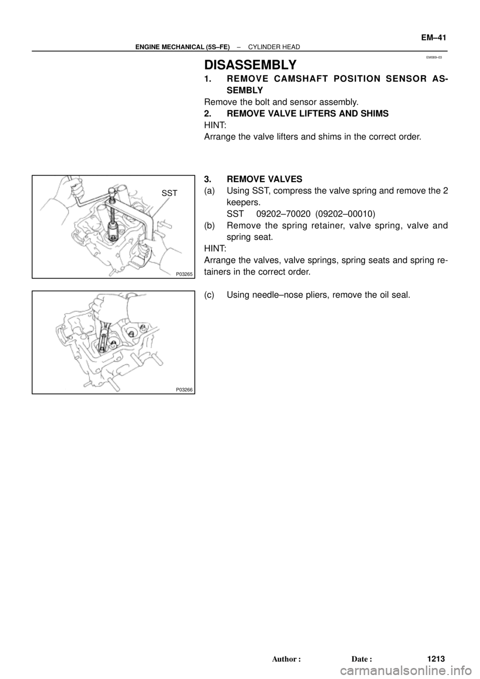
3. REMOVE VALVES
(a) Using SST, compress the valve spring and remove the 2
keepers.
SST 09202±70020 (09202±00010)
(b) Remove the spring retainer, valve spring, valve and
spring seat.
HINT:
Arrange the valves, valve springs, spring seats and spring re-
tainers in the correct order.
(c) Using needle±nose pliers, remove the oil seal.
Page 3437 of 4770
CYLINDER HEAD
EM±45
1217 Author�: Date�:
(d) Check the valve overall length.
Standard overall length:")
EM2534
Overall Length
EM0255
P03272
45° Carbide
Cutter
Z00055
Width
± ENGINE MECHANICAL (5S±FE)CYLINDER HEAD
EM±45
1217 Author�: Date�:
(d) Check the valve overall length.
Standard overall length:
Intake97.40 ± 97.80 mm (3.8346 ± 3.8504 in.)
Exhaust98.25 ± 98.65 mm (3.8681 ± 3.8839 in.)
Minimum overall length:
Intake97.1 mm (3.823 in.)
Exhaust98.0 mm (3.858 in.)
If the overall length is less than minimum, replace the valve.
(e) Check the surface of the valve stem tip for wear.
If the valve stem tip is worn, resurface the tip with a grinder or
replace the valve.
NOTICE:
Do not grind off more than the minimum length.
8. INSPECT AND CLEAN VALVE SEATS
(a) Using a 45° carbide cutter, resurface the valve seats.
Remove only enough metal to clean the seats.
(b) Check the valve seating position.
Apply a light coat of prussian blue (or white lead) to the
valve face. Lightly press the valve against the seat. Do not
rotate valve.
(c) Check the valve face and seat for the following:
�If blue appears 360° around the face, the valve is
concentric. If not, replace the valve.
�If blue appears 360° around the valve seat, the
guide and face are concentric. If not, resurface the
seat.
�Check that the seat contact is in the middle of the
valve face with the following width:
1.0 ± 1.4 mm (0.039 ± 0.055 in.)
Page 3438 of 4770
Z02852
45°
30°
1.0 ± 1.4 mm
Z02853
45° 75°
1.0 ± 1.4 mm
P03273
EM0988
Deviation
EM0801
EM±46
± ENGINE MECHANICAL (5S±FE)CYLINDER HEAD
1218 Author�: Date�:
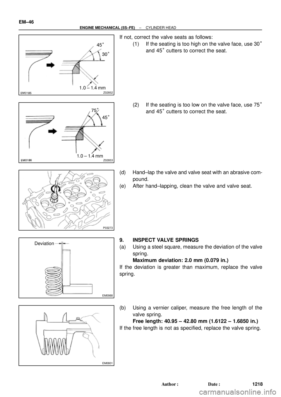
If not, correct the valve seats as follows:
(1) If the seating is too high on the valve face, use 30°
and 45° cutters to correct the seat.
(2) If the seating is too low on the valve face, use 75°
and 45° cutters to correct the seat.
(d) Hand±lap the valve and valve seat with an abrasive com-
pound.
(e) After hand±lapping, clean the valve and valve seat.
9. INSPECT VALVE SPRINGS
(a) Using a steel square, measure the deviation of the valve
spring.
Maximum deviation: 2.0 mm (0.079 in.)
If the deviation is greater than maximum, replace the valve
spring.
(b) Using a vernier caliper, measure the free length of the
valve spring.
Free length: 40.95 ± 42.80 mm (1.6122 ± 1.6850 in.)
If the free length is not as specified, replace the valve spring.
Page 3548 of 4770
EM04T±03
P12683
P12476
SST
P12686
P12720
Magnetic Finger EM±42
± ENGINE MECHANICAL (1MZ±FE)CYLINDER HEAD
1328 Author�: Date�:
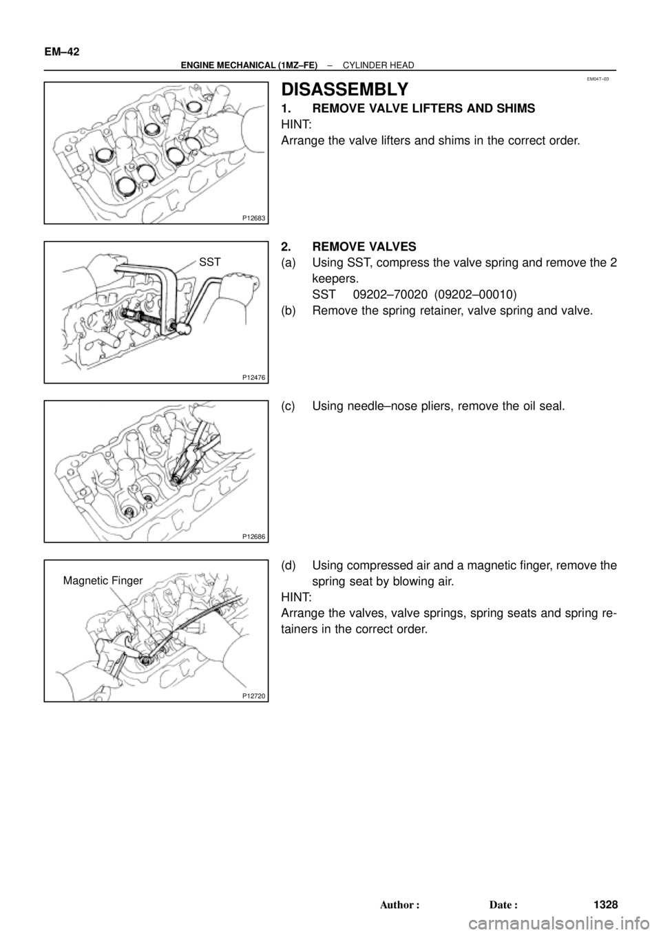
DISASSEMBLY
1. REMOVE VALVE LIFTERS AND SHIMS
HINT:
Arrange the valve lifters and shims in the correct order.
2. REMOVE VALVES
(a) Using SST, compress the valve spring and remove the 2
keepers.
SST 09202±70020 (09202±00010)
(b) Remove the spring retainer, valve spring and valve.
(c) Using needle±nose pliers, remove the oil seal.
(d) Using compressed air and a magnetic finger, remove the
spring seat by blowing air.
HINT:
Arrange the valves, valve springs, spring seats and spring re-
tainers in the correct order.
Page 3552 of 4770
CYLINDER HEAD
1332 Author�: Date�:
(d) Check the valve overall length.
Standard over")
EM2534
Overall Length
EM0255
P12704
P12729
Width
Z03988
45°
1.0 ± 1.4 mm30° EM±46
± ENGINE MECHANICAL (1MZ±FE)CYLINDER HEAD
1332 Author�: Date�:
(d) Check the valve overall length.
Standard overall length:
Intake95.45 mm (3.5779 in.)
Exhaust95.40 mm (3.7559 in.)
Minimum overall length:
Intake94.95 mm (3.7382 in.)
Exhaust94.90 mm (3.7362 in.)
If the overall length is less than minimum, replace the valve.
(e) Check the surface of the valve stem tip for wear.
If the valve stem tip is worn, resurface the tip with a grinder or
replace the valve.
NOTICE:
Do not grind off more than minimum.
11. INSPECT AND CLEAN VALVE SEATS
(a) Using a 45° carbide cutter, resurface the valve seats.
Remove only enough metal to clean the seats.
(b) Check the valve seating position.
Apply a light coat of prussian blue (or white lead) to the
valve face. Lightly press the valve against the seat. Do not
rotate valve.
(c) Check the valve face and seat for the following:
�If blue appears 360° around the face, the valve is
concentric. If not, replace the valve.
�If blue appears 360° around the valve seat, the
guide and face are concentric. If not, resurface the
seat.
�Check that the seat contact is in the middle of the
valve face with the following width:
1.0 ± 1.4 mm (0.039 ± 0.055 in.)
If not, correct the valve seats as follows:
(1) If the seating is too high on the valve face, use 30°
and 45° cutters to correct the seat.