Page 2371 of 4770
RADIATOR
CO±23
1597 Author�: Date�:
INSTALLATION
1. INSTALL NO.1 ELECTRIC COOLING FAN TO RADIA-
TOR
(a) Attach the lower side of the cooling fan to the bracket of")
CO06M±03
S05955
± COOLING (5S±FE)RADIATOR
CO±23
1597 Author�: Date�:
INSTALLATION
1. INSTALL NO.1 ELECTRIC COOLING FAN TO RADIA-
TOR
(a) Attach the lower side of the cooling fan to the bracket of
the radiator.
(b) Install the cooling fan with the 2 bolts.
(c) Connect the ECT switch connector for the cooling fan.
(d) Install the ECT switch wire clamp for the cooling fan to the
bracket of the radiator.
Torque: 5.0 N´m (50 kgf´cm, 44 in.´lbf)
2. INSTALL NO.2 ELECTRIC COOLING FAN TO RADIA-
TOR
(a) Attach the lower side of the cooling fan to the bracket of
the radiator.
(b) Install the cooling fan with the 2 bolts.
Torque: 5.0 N´m (50 kgf´cm, 44 in.´lbf)
3. INSTALL RADIATOR ASSEMBLY
(a) Install the lower radiator hose to the radiator.
(b) A/T:
Install the 2 oil cooler hoses to the radiator.
(c) Install the 2 lower radiator supports to the radiator.
(d) Attach the 2 lower radiator supports on the radiator to the
body brackets.
(e) Install the 2 upper radiator supports with the 2 bolts.
Torque: 12.8 N´m (130 kgf´cm, 9 ft´lbf)
(f) Connect the upper radiator hose to the radiator.
(g) Connect the lower radiator hose to the water inlet.
(h) Connect the radiator reservoir hose to the radiator.
(i) A/T:
Connect the 2 oil cooler hoses to the oil cooler pipes.
(j) Connect the No.1 electric cooling fan connector.
(k) Connect the No.2 electric cooling fan connector.
(l) Connect the ECT switch connector for the electric cooling
fan.
4. FILL WITH ENGINE COOLANT
5. START ENGINE AND CHECK FOR COOLANT LEAKS
Page 2383 of 4770
CO03B±04
± COOLING (1MZ±FE)COOLANT
CO±1
1609 Author�: Date�:
COOLANT
INSPECTION
1. CHECK ENGINE COOLANT LEVEL AT RADIATOR RESERVOIR
The engine coolant level should be between the ºLOWº and ºFULLº lines, when the engine is cold.
If low, check for leaks and add ''Toyota Long Life Coolantº or Equivalent up to the ºFULLº line.
2. CHECK ENGINE COOLANT QUALITY
(a) Remove the radiator cap from the water outlet.
CAUTION:
To avoid the danger of being burned, do not remove the radiator cap while the engine and radiator
are still hot, as fluid and steam can be blown out under pressure.
(b) There should not be any excessive deposits of rust or scale around the radiator cap or water outlet
filler hole, and the coolant should be free from oil.
If excessively dirty, clean the coolant passages and replace the coolant.
(c) Reinstall the radiator cap.
Page 2384 of 4770
COOLANT
1610 Author�: Date�:
REPLACEMENT
1. DRAIN ENGINE COOLANT
(a) Remove the radiator cap from the water outlet.
CAUTION:
To avoid t")
CO03C±04
Z18835
Drain Plug
Drain Plug CO±2
± COOLING (1MZ±FE)COOLANT
1610 Author�: Date�:
REPLACEMENT
1. DRAIN ENGINE COOLANT
(a) Remove the radiator cap from the water outlet.
CAUTION:
To avoid the danger of being burned, do not remove the ra-
diator cap while the engine and radiator are still hot, as fluid
and steam can be blown out under pressure.
(b) Loosen the radiator drain plug and engine drain plugs,
and drain the coolant.
(c) Close the drain plugs.
Torque:
RH engine drain plug on EGR cooler:
7 N´m (70 kgf´cm, 61 in.´lbf)
LH engine drain plug on union:
13 N´m (130 kgf´cm, 9 ft´lbf)
2. FILL ENGINE COOLANT
(a) Slowly fill the system with coolant.
�Use of improper coolants may damage engine cool-
ing system.
�Use ºToyota Long life Coolantº or equivalent and
mix it with plan water according to the manufactur-
er's directions.
�Using of coolant which includes more than 50 %
(freezing protection down to ±35°C (±31°F) or 60 %
(freezing protection down to ±50°C (±58°F)) of eth-
ylene±glycol is recommended but not more than 70
%.
NOTICE:
�Do not use an alcohol type coolant or plain water
alone.
�The coolant should be mixed with plain water (prefer-
ably demineralized water or distilled water).
Capacity: 9.2 liters (9.7 US qts, 8.1 lmp. qts)
(b) Install the radiator cap.
(c) Start the engine, and bleed the cooling system.
(d) If necessary, refill coolant into the reservoir up to the
ºFULLº line.
3. CHECK ENGINE COOLANT FOR LEAKS
4. CHECK ENGINE COOLANT SPECIFIC GRAVITY
CORRECTLY
Page 2385 of 4770
CO03D±04
A06654
RH Fender Apron Seal
Generator Drive BeltEngine Moving
Control Rod
RH Engine Mounting Stay
No.2 RH Engine
Mounting Bracket
Ground Strap PS Pump Drive Belt
Engine Coolant Reservoir Hose
: Specified torqueNo.2 RH Engine
Mounting Stay (M/T)
64 (650, 47)
32 (320, 23)
64 (650, 47)
N´m (kgf´cm, ft´lbf)
± COOLING (1MZ±FE)WATER PUMP
CO±3
1611 Author�: Date�:
WATER PUMP
COMPONENTS
Page 3519 of 4770
EM04N±03
A06654
RH Fender Apron Seal
Generator Drive Belt Engine Moving
Control Rod
RH Engine Mounting Stay
No.2 RH Engine
Mounting Bracket
Ground Strap PS Pump Drive Belt
Engine Coolant Reservoir Hose
: Specified torqueNo.2 RH Engine
Mounting Stay (M/T)
64 (650, 47)
32 (320, 23)
64 (650, 47)
N´m (kgf´cm, ft´lbf)
± ENGINE MECHANICAL (1MZ±FE)TIMING BELT
EM±13
1299 Author�: Date�:
TIMING BELT
COMPONENTS
Page 3521 of 4770
EM04O±04
P18754
P18816
P18817
SST
P18819
SST
± ENGINE MECHANICAL (1MZ±FE)TIMING BELT
EM±15
1301 Author�: Date�:
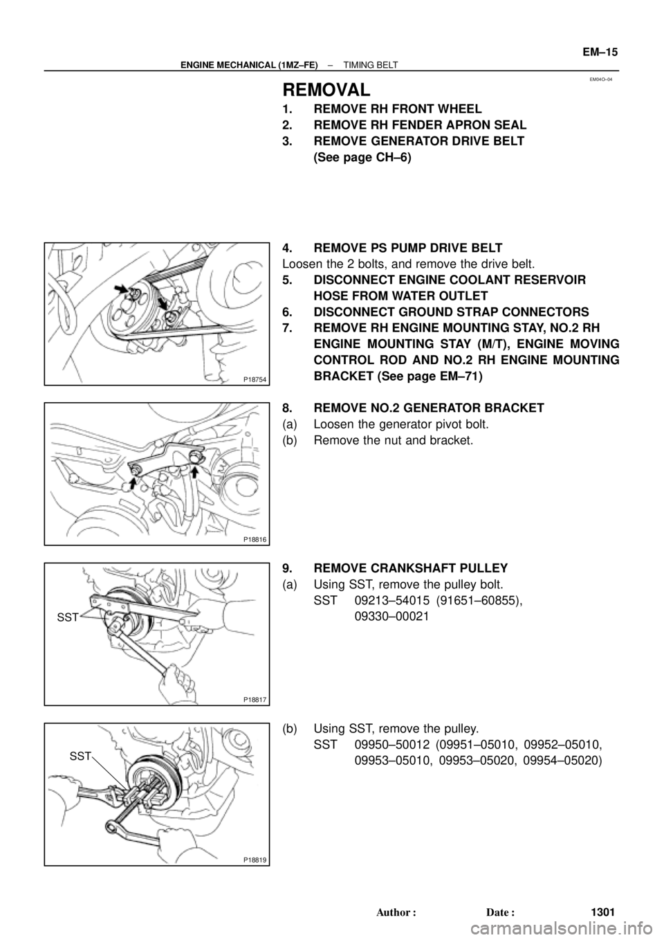
REMOVAL
1. REMOVE RH FRONT WHEEL
2. REMOVE RH FENDER APRON SEAL
3. REMOVE GENERATOR DRIVE BELT
(See page CH±6)
4. REMOVE PS PUMP DRIVE BELT
Loosen the 2 bolts, and remove the drive belt.
5. DISCONNECT ENGINE COOLANT RESERVOIR
HOSE FROM WATER OUTLET
6. DISCONNECT GROUND STRAP CONNECTORS
7. REMOVE RH ENGINE MOUNTING STAY, NO.2 RH
ENGINE MOUNTING STAY (M/T), ENGINE MOVING
CONTROL ROD AND NO.2 RH ENGINE MOUNTING
BRACKET (See page EM±71)
8. REMOVE NO.2 GENERATOR BRACKET
(a) Loosen the generator pivot bolt.
(b) Remove the nut and bracket.
9. REMOVE CRANKSHAFT PULLEY
(a) Using SST, remove the pulley bolt.
SST 09213±54015 (91651±60855),
09330±00021
(b) Using SST, remove the pulley.
SST 09950±50012 (09951±05010, 09952±05010,
09953±05010, 09953±05020, 09954±05020)
Page 3531 of 4770

Join
Line
Join
Line
Length = 460 mm
(18.11 in.)
A04693
SST
P18816
± ENGINE MECHANICAL (1MZ±FE)TIMING BELT
EM±25
1311 Author�: Date�:
14. INSTALL NO.1 TIMING BELT C")
P12982
Length = 240 mm (9.45 in.)
Join
Line
Join
Line
Length = 460 mm
(18.11 in.)
A04693
SST
P18816
± ENGINE MECHANICAL (1MZ±FE)TIMING BELT
EM±25
1311 Author�: Date�:
14. INSTALL NO.1 TIMING BELT COVER
(a) Check that the timing belt cover gaskets have cracks or
peeling, etc.
If the gasket has cracks or peeling, etc., replace it using these
steps:
�Using a screwdriver and gasket scraper, remove all
the old gasket material.
�Thoroughly clean all components to remove all the
loose material.
�Remove the backing paper from a new gasket and
install the gasket evenly to the part of the timing belt
cover shaded black in the illustration.
NOTICE:
When joining 2 gaskets, do not leave a gap between them.
Cut off any excess gasket.
�After installing the gasket, press down on it so that
the adhesive firmly sticks to the timing belt cover.
(b) Install the timing belt cover with the 4 bolts.
Torque: 8.5 N´m (85 kgf´cm, 74 in.´lbf)
15. INSTALL CRANKSHAFT PULLEY
(a) Align the pulley set key with the key groove of the pulley,
and slide on the pulley.
(b) Using SST, install the pulley bolt.
SST 09213±54015 (91651±60855), 09330±00021
Torque: 215 N´m (2,200 kgf´cm, 159 ft´lbf)
16. INSTALL NO.2 GENERATOR BRACKET
Install the generator bracket with the pivot bolt and nut. Do not
tighten the bolt yet.
Torque: (Nut): 28 N´m (290 kgf´cm, 21 ft´lbf)
17. INSTALL NO.2 RH ENGINE MOUNTING BRACKET,
ENGINE MOVING CONTROL ROD, NO.2 RH ENGINE
MOUNTING STAY (M/T) AND RH ENGINE MOUNTING
STAY (See page EM±76)
18. CONNECT GROUND STRAP CONNECTORS
19. CONNECT ENGINE COOLANT RESERVOIR HOSE TO
WATER OUTLET
20. INSTALL PS PUMP DRIVE BELT
21. INSTALL GENERATOR DRIVE BELT
(See page CH±16)
Page 3534 of 4770

EGR Gas Temperature
Sensor Connector
Water Bypass Hose
A06657
PS Pressure TubeAir Intake Chamber Stay
V±Bank Cover
VSV Connector
for EGR
Engine Wire�Gasket
No.2 EGR Pipe
Throttle Position
Sensor Connector
Vacuum Hose
EGR Valve Position Brake Booster12 (120,9)
39 (400,29)
�Gasket
Sensor Connector
IAC Valve
ConnectorAccelerator Cable
Throttle Cable
Purge Hose
Air Assist Hose Hose Vacuum
�Gasket
VSV Connector for ACIS
Engine Coolant
Reservoir Hose
43 (440,32)
ECT Sender
Gauge Connector
ECT Sensor
Connector
Grand Strap
Connector
15 (150,11)
Water Outlet
15 (150,11)
Water Bypass
Hose
Upper Radiator
Hose
Fuel Inlet Hose
Injector Connector Intake Manifold Assembly�Retainer
Heater Hose
�Gasket Ignition Coil
Connector
� Non±reusable part: Specified torque
N´m (kgf´cm, ft´lbf)
19.5 (200, 14)
No.1 Engine
Hanger
VSV Connector for
EVAP
Ground Cable
PCV Hose Ground Cable
Air Intake Chamber
Assembly
� Gasket
High±Tension Cord Set
Spark PlugIgnition Coil
Water Bypass Hose
Ground Strap
DLC1
EM±28
± ENGINE MECHANICAL (1MZ±FE)CYLINDER HEAD
1314 Author�: Date�: