Page 1574 of 4770
AC0MD±01
AC±52
± AIR CONDITIONINGCONDENSER
2534 Author�: Date�:
CONDENSER
ON±VEHICLE INSPECTION
1. INSPECT CONDENSER FINS FOR BLOCKAGE OR DAMAGE
�If the fins are clogged, wash them with water and dry with compressed air.
NOTICE:
Be careful not to damage the fins.
�If the fins are bent, straighten them with a screwdriver or pliers.
2. INSPECT CONDENSER AND FITTINGS FOR LEAKAGE
Using a gas leak detector, check for leakage of refrigerant.
If there is leakage, check the tightening torque at the joints.
Page 1575 of 4770

AC0ME±02
I03836
± AIR CONDITIONINGCONDENSER
AC±53
2535 Author�: Date�:
REMOVAL
1. DISCHARGE REFRIGERANT FROM REFRIGERATION
SYSTEM
HINT:
At the time of installation, please refer to the following item.
Evacuate air from refrigeration system.
Charge system with refrigerant and inspect for leakage of refrig-
erant.
Specified amount: 800 ± 50 g (28.22 ± 1.76 oz.)
2. REMOVE UPPER RADIATOR SUPPORTS
3. REMOVE RECEIVER AND HOLDER
(See page AC±50)
4. DISCONNECT DISCHARGE HOSE
Loosen the nut and disconnect the discharge hose.
Torque: 10 N´m (100 kgf´cm, 7 ft´lbf)
NOTICE:
Cap the open fittings immediately to keep moisture or dirt
out of the system.
HINT:
At the time of installation, please refer to the following item.
Lubricate a new O±ring with compressor oil and install the tube.
5. REMOVE LIQUID TUBE
Loosen the nut and remove the liquid tube.
Torque: 14 N´m (140 kgf´cm, 10 ft´lbf)
NOTICE:
Cap the open fittings immediately to keep moisture or dirt
out of the system.
HINT:
At the time of installation, please refer to the following item.
Lubricate a new O±ring with compressor oil and install the tube.
Page 1584 of 4770
N20246
AC±62
± AIR CONDITIONINGEXPANSION VALVE
2544 Author�: Date�:
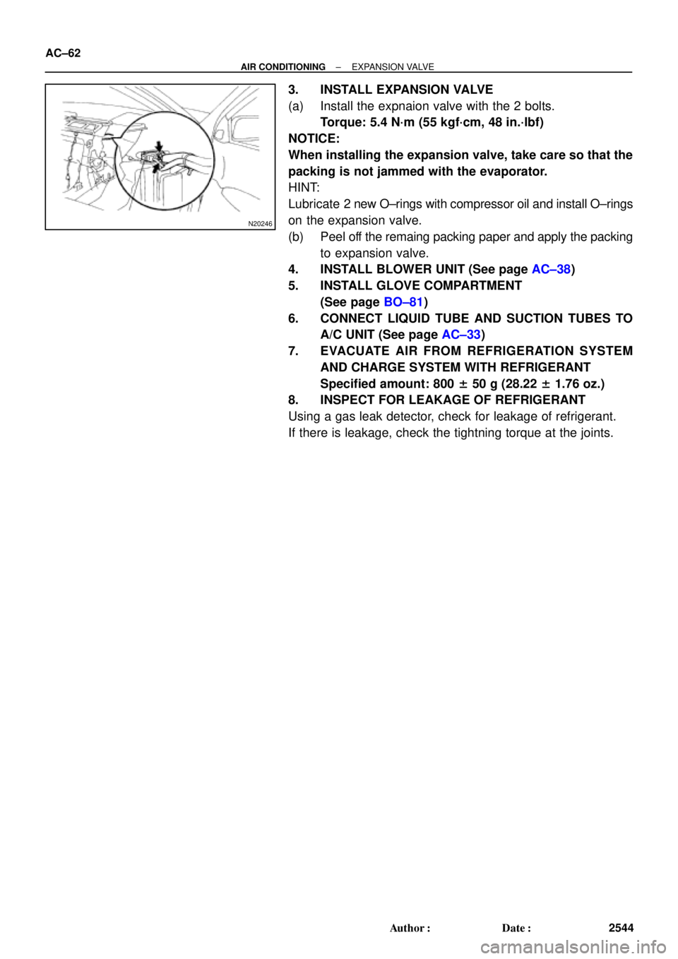
3. INSTALL EXPANSION VALVE
(a) Install the expnaion valve with the 2 bolts.
Torque: 5.4 N´m (55 kgf´cm, 48 in.´lbf)
NOTICE:
When installing the expansion valve, take care so that the
packing is not jammed with the evaporator.
HINT:
Lubricate 2 new O±rings with compressor oil and install O±rings
on the expansion valve.
(b) Peel off the remaing packing paper and apply the packing
to expansion valve.
4. INSTALL BLOWER UNIT (See page AC±38)
5. INSTALL GLOVE COMPARTMENT
(See page BO±81)
6. CONNECT LIQUID TUBE AND SUCTION TUBES TO
A/C UNIT (See page AC±33)
7. EVACUATE AIR FROM REFRIGERATION SYSTEM
AND CHARGE SYSTEM WITH REFRIGERANT
Specified amount: 800 ± 50 g (28.22 ± 1.76 oz.)
8. INSPECT FOR LEAKAGE OF REFRIGERANT
Using a gas leak detector, check for leakage of refrigerant.
If there is leakage, check the tightning torque at the joints.
Page 1590 of 4770
AC0N3±02
N20292
AC±68
± AIR CONDITIONINGPRESSURE SWITCH
2550 Author�: Date�:
REMOVAL
1. DISCHARGE REFRIGERANT FROM REFRIGERATION
SYSTEM
HINT:
At the time of installation, please refer to the following item.
Evacuate air from refrigeration system.
Charge system with refrigerant and inspect for leakage of refrig-
erant.
Specified amount: 800 ± 50 g (28.22 ± 1.76 oz.)
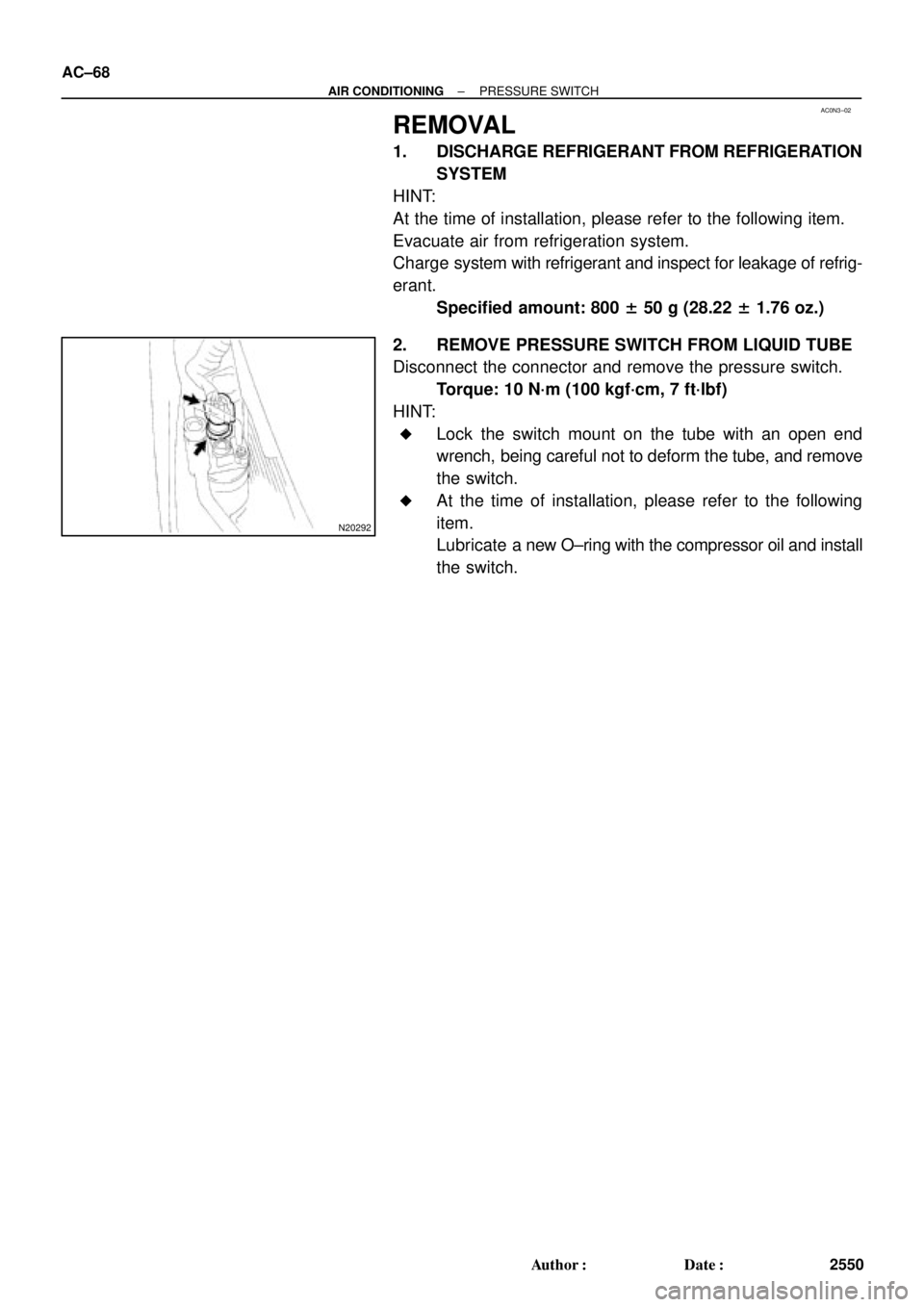
2. REMOVE PRESSURE SWITCH FROM LIQUID TUBE
Disconnect the connector and remove the pressure switch.
Torque: 10 N´m (100 kgf´cm, 7 ft´lbf)
HINT:
�Lock the switch mount on the tube with an open end
wrench, being careful not to deform the tube, and remove
the switch.
�At the time of installation, please refer to the following
item.
Lubricate a new O±ring with the compressor oil and install
the switch.
Page 1618 of 4770
INTRODUCTIONHOW TO USE THIS MANUAL ±
IN±3
CAUTIONS, NOTICES, HINTS:
�CAUTIONS are presented in bold type, and indicate there is a possibility of injury to you or other
people.
�NOTICES are also presented in bold type, and indicate the possibility of damage to the compo-
nents being repaired.
�HINTS are separated from the text but do not appear in bold. They provide additional information
to help you perform the repair efficiently.
SI UNIT
The UNITS given in this manual are primarily expressed according to the SI UNIT (International System
of Unit), and alternately expressed in the metric system and in the English system.
Example:
Torque: 30 N´m (310 kgf´cm, 22 ft´lbf)
Page 1620 of 4770
 Precoated parts are indicated in the component il-
lustrations by the º�º symbol.
7")
INTRODUCTIONGENERAL REPAIR INSTRUCTIONS ±
IN±5
the specified seal lock adhesive to the bolt, nut or
threads.
(c) Precoated parts are indicated in the component il-
lustrations by the º�º symbol.
7. When necessary, use a sealer on gaskets to prevent
leaks.
8. Carefully observe all specifications for bolt tightening
torques. Always use a torque wrench.
9. Use of special service tools (SST) and special service ma-
terials (SSM) may be required, depending on the nature
of the repair. Be sure to use SST and SSM where speci-
fied and follow the proper work procedure. A list of SST
and SSM can be found at the preparation of AX section.
10. When replacing fuses, be sure the new fuse has the cor-
rect amperage rating. DO NOT exceed the rating or use
one with a lower rating.
11. To pull apart electrical connectors, pull on the connector
itself, not the wires.
12. Care must be taken when jacking up and supporting the
vehicle. Be sure to lift and support the vehicle at the prop-
er locations.
(a) If the vehicle is to be jacked up only at the front or
rear end, be sure to block the wheels at the opposite
end in order to ensure safety.
(b) After the vehicle is jacked up, be sure to support it on
stands. It is extremely dangerous to do any work on
a vehicle raised on a jack alone, even for a small job
that can be finished quickly.
Page 1622 of 4770

IATIntake Air TemperatureIntake or Inlet Air Temperature
ICMIgnition Control Module±
IFIIndirect Fuel")
INTRODUCTIONGLOSSARY OF SAE AND TOYOTA TERMS ±
IN±7
IACIdle Air ControlIdle Speed Control (ISC)
IATIntake Air TemperatureIntake or Inlet Air Temperature
ICMIgnition Control Module±
IFIIndirect Fuel InjectionIndirect Injection
IFSInertia Fuel±Shutoff±
ISCIdle Speed Control±
KSKnock SensorKnock Sensor
MAFMass Air FlowAir Flow Meter
MAPManifold Absolute PressureManifold Pressure
Intake Vacuum
MCMixture Control
Electric Bleed Air Control Valve (EBCV)
Mixture Control Valve (MCV)
Electric Air Control Valve (EACV)
MDPManifold Differential Pressure±
MFIMultiport Fuel InjectionElectronic Fuel Injection (EFI)
MILMalfunction Indicator LampCheck Engine Light
MSTManifold Surface Temperature±
MVZManifold Vacuum Zone±
NVRAMNon±Volatile Random Access Memory±
O2SOxygen SensorOxygen Sensor, O2 Sensor (O2S)
OBDOn±Board DiagnosticOn±Board Diagnostic (OBD)
OCOxidation Catalytic ConverterOxidation Catalyst Converter (OC), CCo
OPOpen LoopOpen Loop
PAIRPulsed Secondary Air InjectionAir Suction (AS)
PCMPowertrain Control Module±
PNPPark/Neutral Position±
PROMProgrammable Read Only Memory±
PSPPower Steering Pressure±
PTOXPeriodic Trap OxidizerDiesel Particulate Filter (DPF)
Diesel Particulate Trap (DPT)
RAMRandom Access MemoryRandom Access Memory (RAM)
RMRelay Module±
ROMRead Only MemoryRead Only Memory (ROM)
RPMEngine SpeedEngine Speed
SCSuperchargerSupercharger
SCBSupercharger Bypass±
SFISequential Multiport Fuel InjectionElectronic Fuel Injection (EFI), Sequential Injection
SPLSmoke Puff Limiter±
SRIService Reminder Indicator±
SRTSystem Readiness Test±
STScan Tool±
TBThrottle BodyThrottle Body
TBIThrottle Body Fuel InjectionSingle Point Injection
Central Fuel Injection (Ci)
TCTurbochargerTurbocharger
TCCTorque Converter ClutchTorque Converter
TCMTransmission Control ModuleTransmission ECU (Electronic Control Unit)
TPThrottle PositionThrottle Position
TRTransmission Range±
Page 1625 of 4770
INTRODUCTIONSTANDARD BOLT TORQUE SPECIFICATIONS ±
IN±10
STANDARD BOLT TORQUE SPECIFICATIONS
IN008±02