Page 1548 of 4770
I07051
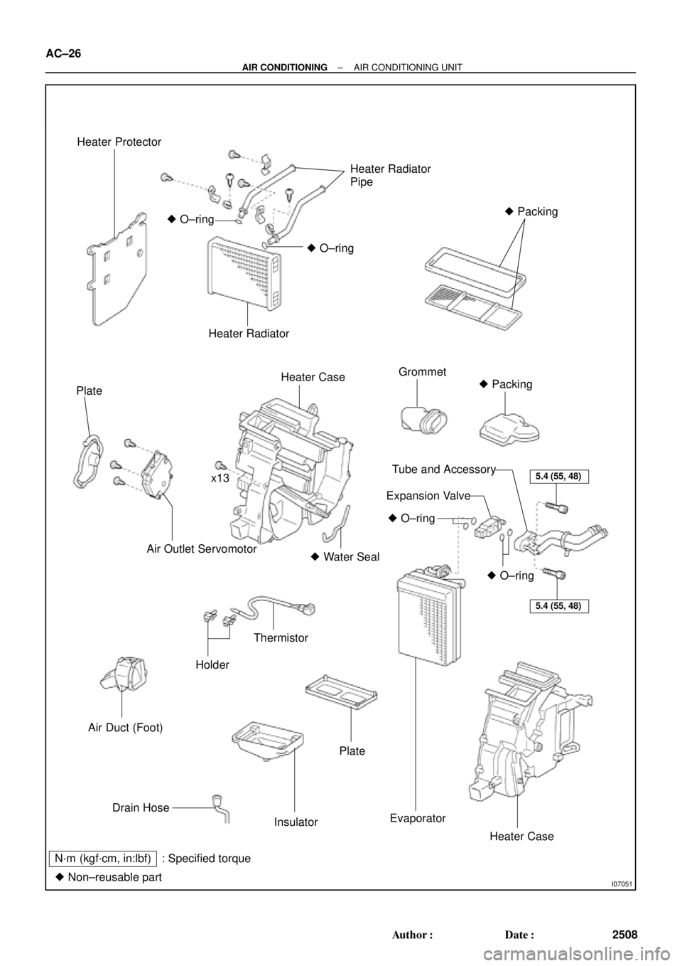
Heater Protector
Heater Radiator
Pipe
� Packing
� O±ring
� O±ring
Heater Radiator
Plate
Heater CaseGrommet
� Packing
x13
Air Outlet Servomotor� Water Seal
Air Duct (Foot)
Holder
Thermistor
5.4 (55, 48)
5.4 (55, 48)
� O±ring
� O±ring
Tube and Accessory
Expansion Valve
Drain Hose
Insulator
Plate
Evaporator
Heater Case
N´m (kgf´cm, in:lbf) : Specified torque
� Non±reusable part
AC±26
± AIR CONDITIONINGAIR CONDITIONING UNIT
2508 Author�: Date�:
Page 1554 of 4770
N20283
N20245
Pin
Pin AC±32
± AIR CONDITIONINGAIR CONDITIONING UNIT
2514 Author�: Date�:
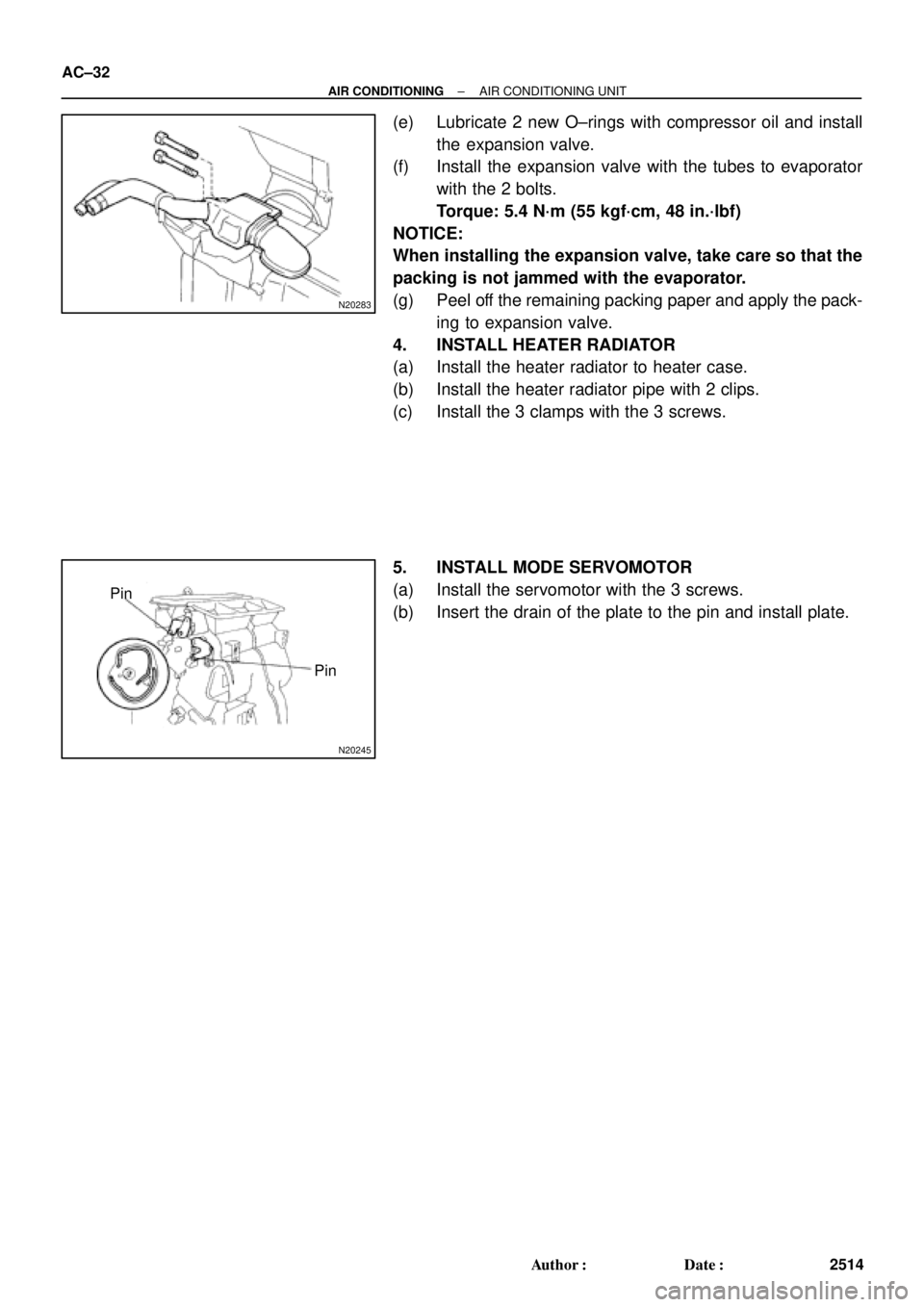
(e) Lubricate 2 new O±rings with compressor oil and install
the expansion valve.
(f) Install the expansion valve with the tubes to evaporator
with the 2 bolts.
Torque: 5.4 N´m (55 kgf´cm, 48 in.´lbf)
NOTICE:
When installing the expansion valve, take care so that the
packing is not jammed with the evaporator.
(g) Peel off the remaining packing paper and apply the pack-
ing to expansion valve.
4. INSTALL HEATER RADIATOR
(a) Install the heater radiator to heater case.
(b) Install the heater radiator pipe with 2 clips.
(c) Install the 3 clamps with the 3 screws.
5. INSTALL MODE SERVOMOTOR
(a) Install the servomotor with the 3 screws.
(b) Insert the drain of the plate to the pin and install plate.
Page 1562 of 4770
AC0M5±02
I03331
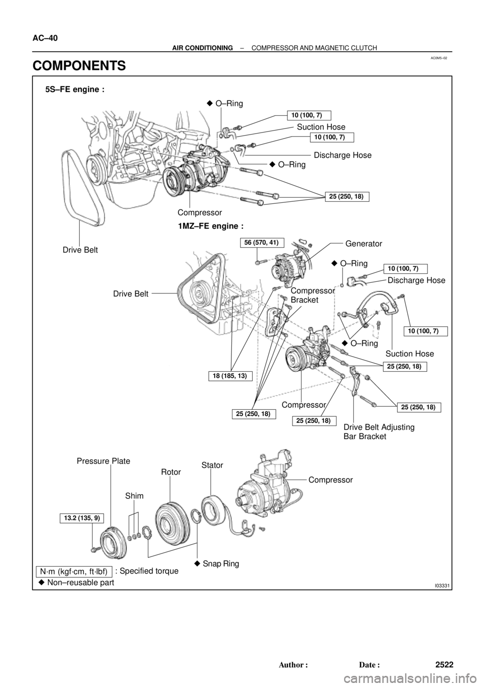
5S±FE engine :
Drive BeltCompressor� O±Ring
Suction Hose
Discharge Hose
10 (100, 7)
10 (100, 7)
� O±Ring
25 (250, 18)
1MZ±FE engine :
� O±Ring
Drive Belt
Drive Belt Adjusting
Bar BracketGenerator
Discharge Hose
10 (100, 7)
10 (100, 7)
25 (250, 18)
Compressor
25 (250, 18)
25 (250, 18)
ShimSuction Hose � O±Ring
25 (250, 18)
56 (570, 41)
18 (185, 13)
13.2 (135, 9)
Rotor Pressure Plate
: Specified torque
N´m (kgf´cm, ft´lbf)Stator
Compressor
� Snap Ring
� Non±reusable part
Compressor
Bracket AC±40
± AIR CONDITIONINGCOMPRESSOR AND MAGNETIC CLUTCH
2522 Author�: Date�:
COMPONENTS
Page 1565 of 4770
AC0M7±02
AC0943
SST
AC0944
SST
AC0945
SST
AC0946
Shim
Pressure
Plate
AC0947
SST
± AIR CONDITIONINGCOMPRESSOR AND MAGNETIC CLUTCH
AC±43
2525 Author�: Date�:
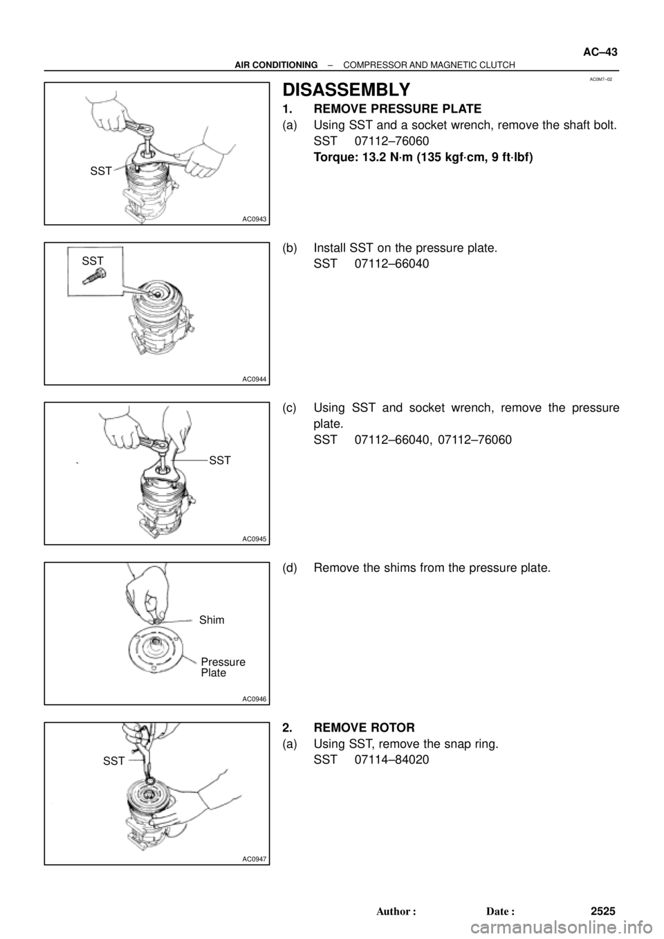
DISASSEMBLY
1. REMOVE PRESSURE PLATE
(a) Using SST and a socket wrench, remove the shaft bolt.
SST 07112±76060
Torque: 13.2 N´m (135 kgf´cm, 9 ft´lbf)
(b) Install SST on the pressure plate.
SST 07112±66040
(c) Using SST and socket wrench, remove the pressure
plate.
SST 07112±66040, 07112±76060
(d) Remove the shims from the pressure plate.
2. REMOVE ROTOR
(a) Using SST, remove the snap ring.
SST 07114±84020
Page 1569 of 4770

(B)
± AIR CONDITIONINGCOMPRESSOR AND MAGNETIC CLUTCH
AC±47
2529 Author�: Date�:
INSTALLATION
1. 5S±FE engine models:
INSTALL COMPRESSOR
(a) Install the compressor with 3 bolts.")
AC0M9±02
N20259
(A)
(B)
± AIR CONDITIONINGCOMPRESSOR AND MAGNETIC CLUTCH
AC±47
2529 Author�: Date�:
INSTALLATION
1. 5S±FE engine models:
INSTALL COMPRESSOR
(a) Install the compressor with 3 bolts.
Torque: 25 N´m (250 kgf´cm, 18 ft´lbf)
(b) Connect the connector.
2. 1MZ±FE engine models:
INSTALL COMPRESSOR
(a) Install the compressor with 3 bolts.
Torque: 25 N´m (250 kgf´cm, 18 ft´lbf)
(b) Install the drive belt adjusting bar bracket with 2 bolts and
nut.
Torque:
Bolt (A): 25 N´m (250 kgf´cm, 18 ft´lbf)
Bolt (B): 18 N´m (185 kgf´cm, 13 ft´lbf)
Nut: 25 N´m (250 kgf´cm, 18 ft´lbf)
(c) Connect the connector.
3. 5S±FE engine models:
CONNECT DISCHARGE AND SUCTION HOSE
Connect the both hoses with the 2 bolts.
Torque: 10 N´m (100 kgf´cm, 7 ft´lbf)
NOTICE:
Hoses should be connected immediately after the caps
have been removed.
HINT:
Lubricate 2 new O±rings with compressor oil and install the
tubes.
4. 1MZ±FE engine models:
INSTALL GENERATOR
(a) Mount generator on the generator bracket with the pivot
bolt and adjusting lock bolt. Do not tighten the bolts yet.
(b) Connect the generator connector.
(c) Connect the generator wire with the nut.
Page 1570 of 4770

AC±48
± AIR CONDITIONINGCOMPRESSOR AND MAGNETIC CLUTCH
2530 Author�: Date�:
5. 1MZ±FE engine models:
CONNECT DISCHARGE HOSE
Connect the discharge hose with the bolt.
Torque: 10 N´m (100 kgf´cm, 7 ft´lbf)
NOTICE:
Hoses should be connected immediately after the caps
have been removed.
HINT:
Lubricate a new O±ring with compressor oil and install the tube.
6. INSTALL SUCTION HOSE
(a) Install the suction hose and tighten the bolt and nut.
Torque:
Piping joint: 32 N´m (330 kgf´cm, 24 ft´lbf)
Block joint: 10 N´m (100 kgf´cm, 7 ft´lbf)
HINT:
Lubricate 2 new O±rings with compressor oil and install the
hose.
(b) Install the suction hose clamping bolt.
(c) Connect the wire harness clamp.
7. INSTALL AND CHECK DRIVE BELT
(See page AC±18, AC±16)
8. CONNECT NEGATIVE (±) TERMINAL CABLE TO BAT-
TERY
9. EVACUATE AIR FROM REFRIGERATION SYSTEM
AND CHARGE SYSTEM WITH REFRIGERANT
Specified amount: 800 ± 50 g (28.22 ± 1.76 oz.)
10. INSPECT FOR LEAKAGE OF REFRIGERANT
Using a gas leak detector, check for leakage of refrigerant.
If there is leakage, check the tightening torque at the joints.
11. INSPECT A/C OPERATION
Page 1571 of 4770
AC0MA±01
± AIR CONDITIONINGRECEIVER
AC±49
2531 Author�: Date�:
RECEIVER
ON±VEHICLE INSPECTION
INSPECT FITTINGS FOR LEAKAGE
Using a gas leak detector, check for leakage.
If there is leakage, check the tightening torque at the joints.
Page 1572 of 4770

AC0MB±02
N20279
AC±50
± AIR CONDITIONINGRECEIVER
2532 Author�: Date�:
REMOVAL
1. DISCHARGE REFRIGERANT FROM REFRIGERATION
SYSTEM
HINT:
At the time of installation, please refer to the following item.
Evacuate air from refrigeration system.
Charge system with refrigerant and inspect for leakage of refrig-
erant.
Specified amount: 800 ± 50 g (28.22 ± 1.76 oz.)
2. REMOVE RADIATOR UPPER SUPPORT SEAL
3. DISCONNECT 2 LIQUID TUBES FROM RECEIVER
Remove the 2 bolts and both tubes.
Torque: 5.4 N´m (55 kgf´cm, 48 in.´lbf)
NOTICE:
Cap the open fittings immediately to keep moisture or dirt
out of the system.
HINT:
At the time of installation, please refer to the following item.
Lubricate 2 new O±rings with compressor oil and install the
tubes.
4. REMOVE RECEIVER
(a) Remove the holder bolt and pull out receiver downward.
HINT:
At the time of installation, please refer to the following item.
If receiver was replaced, add compressor oil to compressor.
Add 20 cc (0.71 fl.oz.)
Compressor oil: ND±OIL 8 or equivalent
(b) Remove the 2 bolts and holder.