Page 3464 of 4770
ENGINE UNIT
1244 Author�: Date�:
22. REMOVE BOLTS HOLDING FRONT ENGINE MOUNT-
ING INSULATOR TO FRONT FRAME
Remove the 3 bolts.
23.")
S05248
S05323
S05249
A06578
Lift EM±72
± ENGINE MECHANICAL (5S±FE)ENGINE UNIT
1244 Author�: Date�:
22. REMOVE BOLTS HOLDING FRONT ENGINE MOUNT-
ING INSULATOR TO FRONT FRAME
Remove the 3 bolts.
23. ATTACH ENGINE SLING DEVICE TO ENGINE HANG-
ERS
Attach the engine chain hoist to the engine hangers.
CAUTION:
Do not attempt to hang the engine by hooking the chain to
any other part.
24. REMOVE ENGINE MOVING CONTROL ROD
Remove the 3 bolts and control rod.
25. REMOVE ENGINE AND TRANSAXLE ASSEMBLY
FROM VEHICLE
(a) Lift the engine out of the vehicle slowly and carefully.
NOTICE:
Make sure the engine is clear of all wiring, hoses and
cables.
(b) Place the engine and transaxle assembly onto the stand.
26. REMOVE FRONT ENGINE MOUNTING INSULATOR
FROM ENGINE
Remove the 4 bolts and mounting insulator.
27. REMOVE REAR ENGINE MOUNTING INSULATOR
FROM ENGINE
Remove the 4 bolts, the mounting insulator.
28. REMOVE NO.2 RH ENGINE MOUNTING BRACKET
FROM ENGINE
Remove the 3 bolts and mounting bracket.
29. A/T:
DISCONNECT THROTTLE CABLE FROM THROTTLE
BODY
Page 3465 of 4770
ENGINE UNIT
EM±73
1245 Author�: Date�:
30. A/T:
REMOVE STARTER (See page ST±5)
31. DISCONNECT CONNECTORS
(a) Disconne")
S05526
TMMK
Made
TMC
Made
A02198
S05530
S05529
Turn
± ENGINE MECHANICAL (5S±FE)ENGINE UNIT
EM±73
1245 Author�: Date�:
30. A/T:
REMOVE STARTER (See page ST±5)
31. DISCONNECT CONNECTORS
(a) Disconnect the VSS connector.
(b) M/T:
Disconnect the back±up light switch connector.
(c) A/T:
Disconnect the PNP switch connector.
(d) A/T:
Disconnect the 2 solenoid connectors.
32. REMOVE NO.1 EXHAUST MANIFOLD STAY
Remove the 2 bolts and manifold stay.
33. REMOVE NO.2 EXHAUST MANIFOLD STAY AND LH
STIFFENER PLATE
(a) TMC Made:
Remove the 2 nuts and manifold stay.
(b) TMMK Made:
Remove the bolt, nut and manifold stay.
(c) Remove the 2 bolts and stiffener plate.
34. REMOVE INTAKE MANIFOLD STAY
Remove the 2 bolts and intake manifold stay.
35. REMOVE RH STIFFENER PLATE
Remove the 4 bolts and stiffener plate.
36. REMOVE EXHAUST PIPE BRACKET, OIL PAN INSU-
LATOR AND NO.2 REAR END PLATE
(a) Remove the 2 bolts and exhaust pipe bracket.
(b) Remove the 2 bolts, oil pan insulator and rear end plate.
37. A/T:
REMOVE TORQUE CONVERTER CLUTCH BOLTS
(a) Turn the crankshaft pulley bolt to gain access to each bolt.
(b) Hold the crankshaft pulley bolt with a wrench, and remove
the 6 bolts.
Page 3466 of 4770
S05531
Wire
Bracket
Ground
Strap
S05314
M/T EM±74
± ENGINE MECHANICAL (5S±FE)ENGINE UNIT
1246 Author�: Date�:
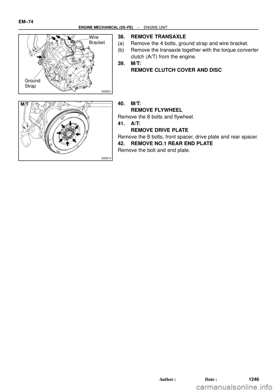
38. REMOVE TRANSAXLE
(a) Remove the 4 bolts, ground strap and wire bracket.
(b) Remove the transaxle together with the torque converter
clutch (A/T) from the engine.
39. M/T:
REMOVE CLUTCH COVER AND DISC
40. M/T:
REMOVE FLYWHEEL
Remove the 8 bolts and flywheel.
41. A/T:
REMOVE DRIVE PLATE
Remove the 8 bolts, front spacer, drive plate and rear spacer.
42. REMOVE NO.1 REAR END PLATE
Remove the bolt and end plate.
Page 3467 of 4770
ENGINE UNIT
EM±75
1247 Author�: Date�:
INSTALLATION
1. INSTALL NO.1 REAR END PLATE
Install the")
EM08G±04
EM7333
Z18989
M/T
1
3
5
8
2 4 67
S05531
Wire
Bracket
Ground
Strap
± ENGINE MECHANICAL (5S±FE)ENGINE UNIT
EM±75
1247 Author�: Date�:
INSTALLATION
1. INSTALL NO.1 REAR END PLATE
Install the end plate with the bolt.
Torque: 9.3 N´m (95 kgf´cm, 82 in.´lbf)
2. M/T:
INSTALL FLYWHEEL
(a) Apply adhesive to 2 or 3 threads of the bolt end.
Adhesive:
Part No. 08833±00070, THREE BOND 1324 or equiva-
lent
(b) Install the flywheel on the crankshaft.
(c) Install and uniformly tighten the 8 bolts in several passes,
in the sequence shown.
Torque: 88 N´m (900 kgf´cm, 65 ft´lbf)
3. A/T:
INSTALL DRIVE PLATE (See step 2)
Torque: 83 N´m (850 kgf´cm, 61 ft´lbf)
4. M/T:
INSTALL CLUTCH DISC AND COVER
5. A/T:
CHECK TORQUE CONVERTER CLUTCH INSTALLA-
TION (A140E: See page AX±25)
6. INSTALL TRANSAXLE TO ENGINE
(a) Attach the transaxle to the engine.
(b) Install the ground strap, wire bracket and 4 bolts.
Torque:
46 N´m (470 kgf´cm, 34 ft´lbf) for 14 mm head
64 N´m (650 kgf´cm, 47 ft´lbf) for 17 mm head
Page 3468 of 4770
ENGINE UNIT
1248 Author�: Date�:
7. A/T:
INSTALL TORQUE CONVERTER CLUTCH BOLTS
(a) Apply a")
Z19014Turn
Black
Colored
Bolt A/T
S05530
A02198
S05526
TMC
Made
TMMK
Made
EM±76
± ENGINE MECHANICAL (5S±FE)ENGINE UNIT
1248 Author�: Date�:
7. A/T:
INSTALL TORQUE CONVERTER CLUTCH BOLTS
(a) Apply adhesive to 2 or 3 threads of the bolt end.
Adhesive:
Part No. 08833±00070, THREE BOND 1324 or equiva-
lent
(b) Hold the crankshaft pulley bolt with a wrench, and install
the 6 bolts evenly.
Torque: 27 N´m (280 kgf´cm, 20 ft´lbf)
HINT:
First tighten the black colored bolt, install the other bolts.
8. INSTALL NO.2 REAR END PLATE, OIL PAN INSULA-
TOR AND EXHAUST PIPE BRACKET
(a) Install the oil pan insulator to the rear end plate.
(b) Install the rear end plate and exhaust pipe bracket with
the 4 bolts.
Torque:
9.3 N´m (95 kgf´cm, 82 in.´lbf) for 10 mm head
19 N´m (195 kgf´cm, 14 ft´lbf) for 12 mm head
9. INSTALL RH STIFFENER PLATE
Install the stiffener plate with the 4 bolts.
Torque: 39 N´m (398 kgf´cm, 29 ft´lbf)
10. INSTALL INTAKE MANIFOLD STAY
Install the manifold stay with the 2 bolts.
Torque: 39 N´m (398 kgf´cm, 29 ft´lbf)
11. INSTALL LH STIFFENER PLATE AND NO.2 EXHAUST
MANIFOLD STAY
(a) TMC Made:
Temporarily install the stiffener plate and manifold stay
with the 2 bolts and 2 nuts.
(b) TMMK Made:
Temporarily install the stiffener plate and manifold stay
with the 3 bolts and nut.
(c) Tighten the 2 bolts holding the stiffener plate to the trans-
axle.
Page 3469 of 4770
ENGINE UNIT
EM±77
1249 Author�: Date�:
Torque:
37 N´m (380 kgf´cm, 27 ft´lbf) for M/T
42 N´m (430 kgf´cm, 31 ft´lbf) for A/T
(d) TMC Made:
Tighten the nut holding t")
± ENGINE MECHANICAL (5S±FE)ENGINE UNIT
EM±77
1249 Author�: Date�:
Torque:
37 N´m (380 kgf´cm, 27 ft´lbf) for M/T
42 N´m (430 kgf´cm, 31 ft´lbf) for A/T
(d) TMC Made:
Tighten the nut holding the manifold stay to the cylinder
block.
Torque: 58 N´m (591 kgf´cm, 43 ft´lbf)
(e) TMMK Made:
Tighten the bolt holding the manifold stay to the cylinder
block.
Torque: 42 N´m (425 kgf´cm, 31 ft´lbf)
(f) Tighten the nut holding the manifold stay to the exhaust
manifold.
Torque: 42 N´m (425 kgf´cm, 31 ft´lbf)
12. INSTALL NO.1 EXHAUST MANIFOLD STAY
Install the manifold stay with the 2 bolts.
Torque: 42 N´m (425 kgf´cm, 31 ft´lbf)
13. CONNECT CONNECTORS
(a) Connect the VSS connector.
(b) M/T:
Connect the back±up light switch connector.
(c) A/T:
Connect the PNP switch connector.
(d) A/T:
Connect the 2 solenoid connectors.
14. A/T:
INSTALL STARTER (See page ST±19)
15. A/T:
INSTALL THROTTLE CABLE TO THROTTLE BODY
16. INSTALL NO.2 RH ENGINE MOUNTING BRACKET TO
ENGINE
Install the mounting insulator with the 3 bolts.
Torque: 52 N´m (530 kgf´cm, 38 ft´lbf)
17. INSTALL REAR ENGINE MOUNTING INSULATOR TO
ENGINE
Install the mounting insulator with the 4 bolts.
Torque: 64 N´m (650 kgf´cm, 47 ft´lbf)
18. INSTALL FRONT ENGINE MOUNTING INSULATOR TO
ENGINE
Install the mounting insulator with the 4 bolts.
Torque: 64 N´m (650 kgf´cm, 47 ft´lbf)
Page 3470 of 4770
ENGINE UNIT
1250 Author�: Date�:
19. INSTALL ENGINE AND TRANSAXLE ASSEMBLY IN
VEHICLE
(a) Attach the engine sling devic")
A06577
Lower
S05249
S05248
S05247
S05254
M/T EM±78
± ENGINE MECHANICAL (5S±FE)ENGINE UNIT
1250 Author�: Date�:
19. INSTALL ENGINE AND TRANSAXLE ASSEMBLY IN
VEHICLE
(a) Attach the engine sling device to the engine hangers.
(b) Lower the engine into the engine compartment.
Tilt the transaxle downward, and lower the engine.
(c) Keep the engine level, and attach front and rear mount-
ings to the front frame.
20. INSTALL ENGINE MOVING CONTROL ROD
Install the control rod with the 3 bolts.
Torque: 64 N´m (650 kgf´cm, 47 ft´lbf)
21. INSTALL BOLTS HOLDING FRONT ENGINE MOUNT-
ING INSULATOR TO FRONT FRAME
Install the 3 bolts.
Torque:
TMC made
80 N´m (820 kgf´cm, 59 ft´lbf)
TMMK made
44 N´m (450 kgf´cm, 32 ft´lbf) for silver color
66 N´m (670 kgf´cm, 49 ft´lbf) for green color
22. INSTALL NUTS HOLDING REAR ENGINE MOUNTING
INSULATOR TO FRONT FRAME
(a) Install the 3 nuts.
Torque: 66 N´m (670 kgf´cm, 49 ft´lbf)
(b) Install the 2 hole plugs.
23. INSTALL BOLTS HOLDING LH ENGINE MOUNTING
INSULATOR TO FRONT FRAME
M/T:
Install the 3 bolts.
Torque: 64 N´m (650 kgf´cm, 47 ft´lbf)
Page 3471 of 4770
ENGINE UNIT
EM±79
1251 Author�: Date�:
A/T:
Install the 4 bolts.
Torque: 64 N´m (650 kgf´cm, 47 ft´lbf)
24. REMOVE ENGINE SLI")
S04616
A/T
S05246
S05250
Connector
S05253
± ENGINE MECHANICAL (5S±FE)ENGINE UNIT
EM±79
1251 Author�: Date�:
A/T:
Install the 4 bolts.
Torque: 64 N´m (650 kgf´cm, 47 ft´lbf)
24. REMOVE ENGINE SLING DEVICE
25. CONNECT TRANSAXLE CONTROL CABLE(S) TO
TRANSAXLE
26. INSTALL PS PUMP
(a) Install the PS pump with the 2 bolts.
Torque: 43 N´m (440 kgf´cm, 32 ft´lbf)
(b) Install the drive belt.
(c) Connect the PS oil pressure switch connector.
27. INSTALL A/C COMPRESSOR
(a) Install the cylinder block insulator and A/C compressor
with the 3 bolts.
Torque: 25.5 N´m (260 kgf´cm, 19 ft´lbf)
(b) Install the drive belt.
(c) Connect the A/C compressor connector.
28. M/T:
INSTALL CLUTCH RELEASE CYLINDER AND TUBE
TO TRANSAXLE
29. M/T:
INSTALL STARTER (See page ST±19)
30. INSTALL DRIVE SHAFTS (See page SA±24)
31. CONNECT ENGINE WIRE TO CABIN
(a) Push in the engine wire through the cowl panel. Install the
grommet.
(b) Connect the 3 engine ECM connectors.
(c) Connect the 3 cowl wire connectors to the connectors on
the bracket.
(d) Install the under cover.
32. CONNECT CONNECTORS, WIRES, CABLES,
CLAMPS AND HOSES
(a) Connect the generator wire.