Page 3456 of 4770

EM0YV±01
A02195
Radiator Reservoir Hose
Generator Drive BeltUpper Radiator
Hose
Support BracketFront Exhaust Pipe PS Oil Pressure Switch
ConnectorBattery TrayBattery
PS Pump Drive Belt
PS Pump
Support Stay Upper Radiator Support
Lower Radiator Hose
A/C Compressor
Cylinder Block Insulator
LH Front Fender Apron Seal
Oil Cooler Hose (A/T)
Cruise Control ActuatorEVAP Hose
Air Filter Upper Radiator
Support
EVAP Hose Hood
PCV Hose
Support
Bracket � Gasket
�
� Non±reusable part� Gasket
�Clamp
N´m (kgf´cm, ft´lbf)
62 (630, 46)
56 (570, 41)
�
: Specified torque
Washer Hose
for Windshield
No.1 Electric
Cooling Fan
Connector
ECT Switch
Connector No.2 Electric
Cooling Fan
ConnectorRadiator
Assembly
A/C Compressor
ConnectorLower Radiator
Support
RH Front Fender
Aplon Seal
Cruise
Control
Actuator
Connector
Battery
Hold±Down
ClampAir Cleaner
Case
VSV
Connector
for EVAP
EVAP
Hose
IAT Sensor
Connector
Air
Cleaner
Cap
EM±64
± ENGINE MECHANICAL (5S±FE)ENGINE UNIT
1236 Author�: Date�:
ENGINE UNIT
COMPONENTS
Page 3457 of 4770
A01565
Engine Wire Clamp
Brake Booster
Vacuum Hose
DLC1
Ground Strap
Connector
Generator
Wire
Wire
Clamp
Generator
ConnectorMAP Sensor
Vacuum HoseMAP Sensor
Connector
Fuel Inlet Hose
Engine
Wire
Starter
Connector
Starter
CableEngine
Wire
ProtectorGround
Cable (M/T)
Ground Strap Connector Wire
Clamp
Ground
Cable (A/T)
Heater
Hose
A01658
No.2 Instrument Panel
Under Cover
Cowl Side Trim Front Door Inside Scuff Plate
Engine Wire
± ENGINE MECHANICAL (5S±FE)ENGINE UNIT
EM±65
1237 Author�: Date�:
Page 3458 of 4770
A02188
Engine Moving Control Rod
Engine and
Transaxle Assembly
Front Engine
Mounting Insulator
RH Drive Shaft
Lower Suspension ArmLH Drive Shaft No.2 RH Engine
Mounting BracketRear Engine
mounting
Insulator
Transaxle
Shift
Control
Cable
(A/T)
Tie Rod End
Lock CapTransaxle Shift
Control Cable
Clutch Release Cylinder and Tube Engine Wire
��Starter M/T
N´m (kgf´cm, ft´lbf)
64 (650, 47)
64 (650, 47)
127 (1,300, 94)
52 (530, 38)
64 (650, 47)
66 (670, 49)
49 (500, 36)
64 (650, 47)
64 (650, 47)
64 (650, 47)
294 (3,000, 217)
TMC Made
80 (820, 59)
TMMK Made
44 (450, 32) for Silver Color
66 (670, 49) for Green Color
: Specified torque
� Non±reusable part
EM±66
± ENGINE MECHANICAL (5S±FE)ENGINE UNIT
1238 Author�: Date�:
Page 3459 of 4770
S05316
M/T
Engine
No.2 Exhaust
Manifold Stay
(TMMK Made)
(TMC Made)
Exhaust Pipe Bracket
Oil Pan
Insulator
No.1 Exhaust
Manifold Stay
Back±Up Light Switch ConnectorNo.2 Rear End Plate Flywheel
LH Stiffener Plate
Clutch Disk
Clutch Cover
Engine Wire
VSS Connector
Wire Clamp
Ground Strap
Transaxle No.1 Rear End PlateIntake Manifold
Stay RH Stiffener Plate
N´m (kgf´cm, ft´lbf)
� Precoated partx 8
88 (900, 65)
19 (195, 14)
64(650, 47)
64(650, 47)
64(650, 47)64(650, 47)
�
: Specified torquex 6
± ENGINE MECHANICAL (5S±FE)ENGINE UNIT
EM±67
1239 Author�: Date�:
Page 3460 of 4770
A02187
A/T
Engine
No.2 Exhaust
Manifold Stay
(TMC Made)
Exhaust Pipe Bracket
Oil Pan
InsulatorLH Stiffener Plate
Engine Wire
VSS Connector
Wire Clamp
Ground Strap No.1 Rear End PlateIntake Manifold
Stay RH Stiffener Plate
N´m (kgf´cm, ft´lbf)
� Precoated partx 8 (TMMK Made)
No.2 Rear End Plate
Transaxle No.1 Exhaust
Manifold Stay
PNP Switch
Connector
StarterThrottle Cable Clamp
Solenoid Connector
Front SpacerDrive Plate
Rear Spacer
Throttle Cable
Solenoid Connector x 6
83 (850, 61)27 (280, 20)
66 (670, 48)
66 (670, 20)
66 (670, 48)
66 (670, 48)
� �
: Specified torque
EM±68
± ENGINE MECHANICAL (5S±FE)ENGINE UNIT
1240 Author�: Date�:
Page 3461 of 4770
ENGINE UNIT
EM±69
1241 Author�: Date�:
REMOVAL
1. REMOVE HOOD
2. REMOVE FRONT FENDER APRON SEALS
3. DRAIN ENGINE COOLANT
4. DRAIN ENGINE OIL
5. DISCONNEC")
EM08F±04
S05251
± ENGINE MECHANICAL (5S±FE)ENGINE UNIT
EM±69
1241 Author�: Date�:
REMOVAL
1. REMOVE HOOD
2. REMOVE FRONT FENDER APRON SEALS
3. DRAIN ENGINE COOLANT
4. DRAIN ENGINE OIL
5. DISCONNECT ACCELERATOR CABLE
6. REMOVE AIR CLEANER CAP
(a) Disconnect the IAT sensor connector.
(b) Disconnect the VSV connector for the EVAP
(c) Disconnect the PCV hose from the cylinder head cover.
(d) Disconnect the EVAP hose from the throttle body.
(e) Disconnect the EVAP hose from the VSV.
(f) Disconnect the 2 clamps, and disconnect the air cleaner
cap from the air cleaner case.
(g) Loosen hose clamp, and disconnect the air cleaner hose
from the throttle body.
(h) Remove the air cleaner cap and hose assembly.
7. REMOVE AIR CLEANER CASE
(a) Remove the air filter.
(b) Remove the 3 bolts and air cleaner case.
8. REMOVE BATTERY AND TRAY
9. REMOVE CRUISE CONTROL ACTUATOR
10. REMOVE RADIATOR (See page CO±18)
11. REMOVE FRONT EXHAUST PIPE
(a) Remove the 2 bolts holding the support stay to the sup-
port bracket.
(b) Remove the 2 bolts holding the support bracket to the
front frame.
(c) Remove the 2 bolts and 2 nuts holding the front exhaust
pipe to the center exhaust pipe.
(d) Remove the 3 nuts holding the front exhaust pipe to the
exhaust manifold.
(e) Remove the front exhaust pipe and 2 gaskets.
(f) Remove the nut and support bracket.
12. DISCONNECT CONNECTORS, WIRES, CABLES,
CLAMPS AND HOSES
(a) Disconnect the generator wire.
(b) Disconnect the generator connector.
(c) Disconnect the wire clamp from the generator.
(d) Disconnect the starter cable.
(e) Disconnect the starter connector.
(f) Disconnect the DLC1 from the bracket.
Page 3462 of 4770
ENGINE UNIT
1242 Author�: Date�:
(g) Disconnect the engine wire clamp from the bracket on the
RH fender apron.
(h) Disconnect the MAP sensor connector.
(i)")
S05253
EM±70
± ENGINE MECHANICAL (5S±FE)ENGINE UNIT
1242 Author�: Date�:
(g) Disconnect the engine wire clamp from the bracket on the
RH fender apron.
(h) Disconnect the MAP sensor connector.
(i) Disconnect the wire clamp from the bracket for the MAP
sensor.
(j) Disconnect the 2 ground strap connectors from the RH
fender apron.
(k) Disconnect the 2 ground strap connectors from the LH
fender apron.
(l) Disconnect the engine wire protector clamp from the bat-
tery bracket.
(m) Disconnect the engine wire from the clamp on the fuel fil-
ter.
(n) Disconnect the ground cable from the transaxle.
(o) Disconnect the brake booster vacuum hose from the in-
take manifold.
(p) Disconnect the heater hose from the water outlet.
(q) Disconnect the heater hose from the water bypass pipe.
(r) Disconnect the fuel inlet hose from the fuel filter.
(s) Disconnect the MAP sensor vacuum hose from the gas
filter on the intake manifold.
13. DISCONNECT ENGINE WIRE FROM CABIN
(a) Remove the under cover.
(b) Disconnect the 3 ECM connectors.
(c) Disconnect the 3 cowl wire connectors from the connec-
tors on the bracket.
(d) Disconnect the grommet from the cowl panel, and pull out
the engine wire.
14. REMOVE DRIVE SHAFTS (See page SA±17)
15. DISCONNECT TRANSAXLE CONTROL CABLE(S)
FROM TRANSAXLE
16. M/T:
REMOVE STARTER (See page ST±5)
17. M/T:
DISCONNECT CLUTCH RELEASE CYLINDER AND
TUBE FROM TRANSAXLE
Page 3463 of 4770
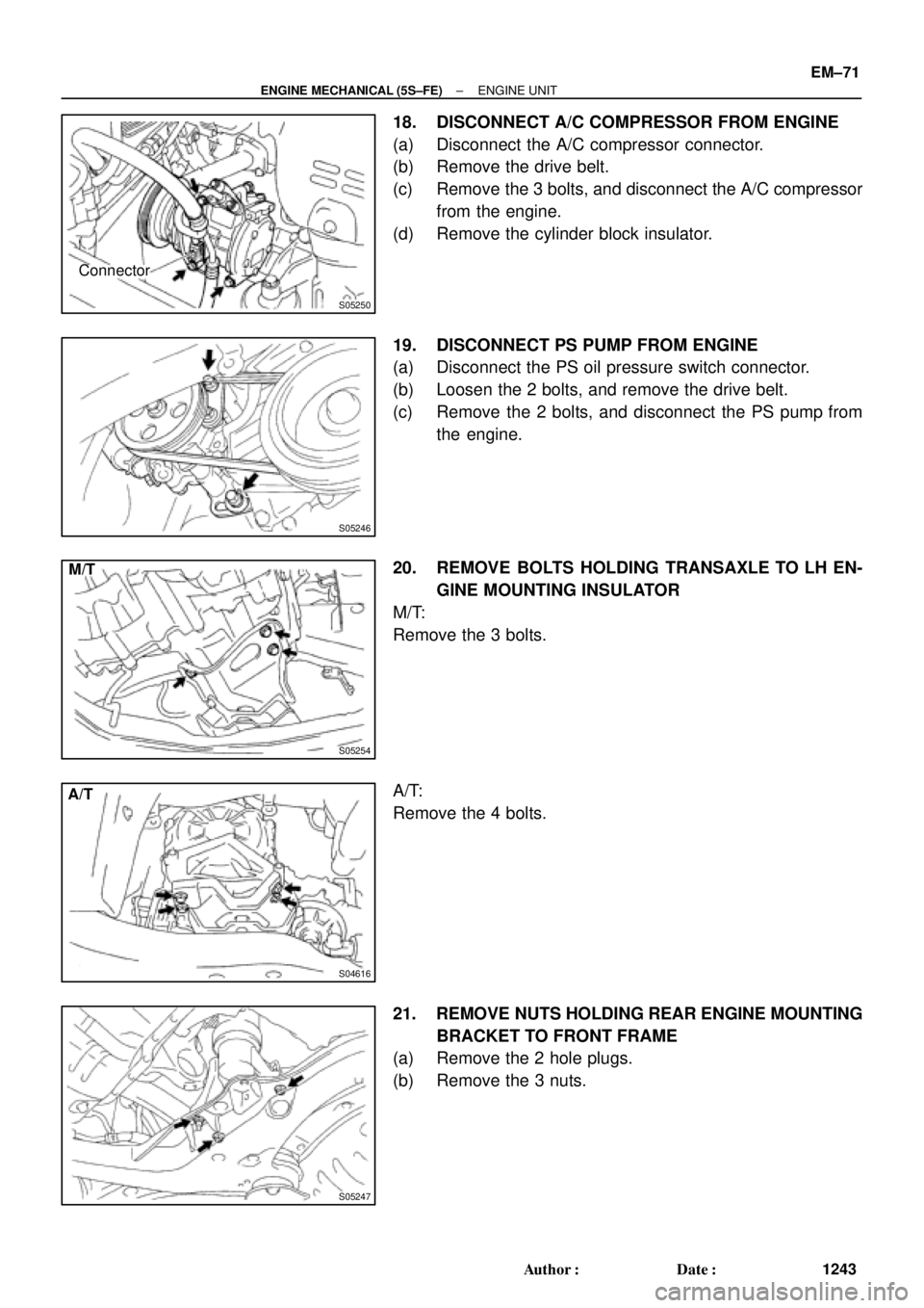
S05250
Connector
S05246
S05254
M/T
S04616
A/T
S05247
± ENGINE MECHANICAL (5S±FE)ENGINE UNIT
EM±71
1243 Author�: Date�:
18. DISCONNECT A/C COMPRESSOR FROM ENGINE
(a) Disconnect the A/C compressor connector.
(b) Remove the drive belt.
(c) Remove the 3 bolts, and disconnect the A/C compressor
from the engine.
(d) Remove the cylinder block insulator.
19. DISCONNECT PS PUMP FROM ENGINE
(a) Disconnect the PS oil pressure switch connector.
(b) Loosen the 2 bolts, and remove the drive belt.
(c) Remove the 2 bolts, and disconnect the PS pump from
the engine.
20. REMOVE BOLTS HOLDING TRANSAXLE TO LH EN-
GINE MOUNTING INSULATOR
M/T:
Remove the 3 bolts.
A/T:
Remove the 4 bolts.
21. REMOVE NUTS HOLDING REAR ENGINE MOUNTING
BRACKET TO FRONT FRAME
(a) Remove the 2 hole plugs.
(b) Remove the 3 nuts.


(TMC Made)
Exhaust Pipe Bracket
Oil Pan
Insulator
No.1 Exhaust
Manifold Stay
Back±Up Light Switch ConnectorNo.2 Rear End Plate Flywheel
LH Sti")

Exhaust Pipe Bracket
Oil Pan
InsulatorLH Stiffener Plate
Engine Wire
VSS Connector
Wire Clamp
Ground Strap No.1 Rear End PlateIntake Manifold
St")