Page 319 of 4770

A pressure feeding lubrication system has been adopted to supply oil to the moving parts of this
engine. The lubrication system consists of an oil pan, oil pump, oil filter and other external parts
which supply oil to the moving parts in the engine block. The oil circuit is shown in the illustration
at the top of the previous page. Oil from the oil pan is pumped up by the oil pump. After it passes
through the oil filter, it is through the various oil holes in the crankshaft and cylinder block. After
passing through the cylinder block and performing its lubricating function, the oil is returned by
gravity to the oil pan. A dipstick on the center left side of the cylinder block is provided to check
the oil level.
OIL PUMP
The oil pump pumps up oil from the oil pan and feeds it under pressure to the various parts of the
engine. An oil strainer is mounted in front of the inlet to the oil pump to remove impurities. The
oil pump itself is a trochoid type pump, inside of which is a drive rotor and a driven rotor. When
the drive rotor rotates, the driven rotor rotates in the same direction, and since the axis of the
drive rotor shaft is different from the center of the driven rotor, the space between the two rotors
changes as they rotate. Oil is drawn in when the space widens and is discharged when the space
becomes narrow.
OIL PRESSURE REGULATOR (RELIEF VALVE)
At high engine speeds, the engine oil supplied by the oil pump exceeds the capacity of the engine
to utilize it. For that reason, the oil pressure regulator works to prevent an oversupply of oil.
During normal oil supply, a coil spring and valve keep the bypass closed, but when too much oil
is being fed, the pressure becomes extremely high, overpowering the force of the spring and
opening the valves. This allows the excess oil to flow through the valve and return to the oil pan.
OIL FILTER
The oil filter is a full flow type filter with a relief valve built into the paper filter element. Particles
of metal from wear, airborne dirt, carbon and other impurities can get into the oil during use and
could cause accelerated wear or seizing if allowed to circulate through the engine. The oil filter,
integrated into the oil line, removes these impurities as the oil passes through it. The filter is
mounted outside the engine to simplify replacement of the filter element. A relief valve is also
included ahead of the filter element to relieve the high oil pressure in case the filter element
becomes clogged with impurities. The relief valve opens when the oil pressure overpowers the
force of the spring. Oil passing through the relief valve bypasses the oil filter and flows directly
into the main oil hole in the engine.
± 5S±FE ENGINELUBRICATION SYSTEMEG1±269
Page 509 of 4770

30
ENGINE
5S±FE ENGINE
� DESCRIPTION
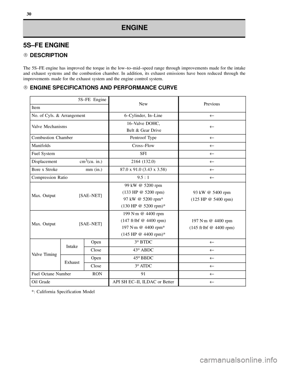
The 5S±FE engine has improved the torque in the low±to±mid±speed range through improvements made for the intake
and exhaust systems and the combustion chamber. In addition, its exhaust emissions have been reduced through the
improvements made for the exhaust system and the engine control system.
� ENGINE SPECIFICATIONS AND PERFORMANCE CURVE
5S±FE EngineNewPreviousItemNewPrevious
No. of Cyls. & Arrangement6±Cylinder, In±Lineu
Valve Mechanisms16±Valve DOHC,
Belt & Gear Driveu
Combustion ChamberPentroof Typeu
ManifoldsCross±Flowu
Fuel SystemSFIu
Displacement cm3(cu. in.)2164 (132.0)u
Bore x Stroke mm (in.)87.0 x 91.0 (3.43 x 3.58)u
Compression Ratio9.5 : 1u
Max. Output [SAE±NET]
99 kW @ 5200 rpm
(133 HP @ 5200 rpm)
97 kW @ 5200 rpm*
(130 HP @ 5200 rpm)*
93 kW @ 5400 rpm
(125 HP @ 5400 rpm)
Max. Output [SAE±NET]
199 N.m @ 4400 rpm
(147 ft
.lbf @ 4400 rpm)
197 N
.m @ 4400 rpm*
(145 HP @ 4400 rpm)*
197 N.m @ 4400 rpm
(145 ft
.lbf @ 4400 rpm)
IntakeOpen3o BTDCu
Valve Timing
IntakeClose43o ABDCuValve Timing
ExhaustOpen45o
BBDCuExhaustClose3o
ATDCu
Fuel Octane Number RON91u
Oil GradeAPI SH EC±II, ILDAC or Betteru
*: California Specification Model
Page 521 of 4770

42ENGINEÐ5S±FE ENGINE
5. Main Components of Engine Control System
The following table compares the main components of the new 5S±FE engine, and previous 5S±FE engine.
Model
NewPreviousComponentNewPrevious
Manifold Absolute Pressure SensorSemiconductoru
Throttle Position SensorLinear Typeu
Crankshaft Position SensorPick±Up Coil Type, 1u
Camshaft Position SensorPick±Up Coil Type, 1Ð
DistributorCamshaft PositionPick Up Coil Type 1DistributorSensorÐPick±Up Coil Type, 1
Knock SensorBuilt±In Piezoelectric
Element Type 1u
Oxygen Sensor
Heated Oxygen Sensor
(Bank 1, Sensor 1)*
1
(Bank 1, Sensor 2)
Air Fuel Ratio Sensor*
2
Oxygen Sensor
(Bank 1, Sensor 1)
(Bank 1, Sensor 2)
Injector2±Hole Typeu
IAC ValveRotary Solenoid Typeu
*1: Except for California Specification Models.
*
2: Only for California Specification Models.
Camshaft Position Sensor
The camshaft position sensor is mounted onto the
cylinder head. Using the protusion that is provided
on the timing pulley, the sensor generates 1 signal
for every revolution. This signal is then sent to the
ECM as a cranskshaft angle system.
Page 523 of 4770

44ENGINEÐ1MZ±FE ENGINE
1MZ±FE ENGINE
� DESCRIPTION
The 1MZ±FE engine has achieved a reduction in exhaust emissions through the adoption of the fuel returnless system
and the changes made onto the EGR control system.
� ENGINE SPECIFICATIONS AND PERFORMANCE CURVE
1MZ±FE EngineNewPreviousItemNewPrevious
No. of Cyls. & Arrangement6±Cylinder, V Typeu
Valve Mechanisms24±Valve DOHC,
Belt & Gear Driveu
Combustion ChamberPentroof Typeu
ManifoldsCross±Flowu
Fuel SystemsSFIu
Displacement cm3(cu. in.)2995 (182.7)u
Bore x Stroke mm (in.)87.5 x 83.0 (3.44 x 3.27)u
Compression Ratio10.5 : 1u
Max. Output {SAE_NET]145 kW @ 5200 rpm
(194 HP @ 5200 rpm)140 kW @ 5200 rpm
(188 HP @ 5200 rpm)
Max. Output {SAE_NET]283 N.m @ 4400 rpm
(209 ft
.lbf @ 4400 rpm)
275 N.m @ 4400 rpm
(203 ft
.lbf @ 4400 rpm)
IntakeOpen4o BTDCu
Valve Timing
IntakeClose44o ABDCuValve Timing
ExhaustOpen46oBBDCuExhaustClose2o
ATDCu
Fuel Octane Number RON91 OR Higheru
Oil GradeAPI SH EC±II, ILDAC or Betteru
Premium unleaded gasoline (96RON) is used for the above specifications.
Page 535 of 4770
56CHASSISÐMANUAL TRANSAXLE
MANUAL TRANSAXLE
� DESCRIPTION
�The 5S±FE engine model uses the same S51 manual transaxle as in the previous model.
�The 1MZ±FE engine model ahs newly adopted the E153 manual transaxle. The basic construction and operation
of the E153 manual transaxle are the same as those of the '95 MR2. However, the differential gear ratio has been
changed to accommodate the characteristics of the engine.
�Specifications�
Model
NewPrevious'95 MR2
Transaxle TypeS51E153S51E153
Engine Type5S FE1MZ FE5S FE3S GTEItem5S±FE1MZ±FE5S±FE3S±GTE
1st3.5383.2303.5383.230
Gear2nd1.9601.9131.9601.913Gear
Ratio3rd1.2501.2581.2501.258
4th0.9450.9180.9450.918
5th0.731uuu
Reverse3.1533.5453.15347
Differential Gear Ratio3.9443.9333.9444.285
Oil Capacity
liters (US qts, Imp. qts)2.6 (2.7, 2.3)4.2 (4.4, 3.7)2.6 (2.7, 2.3)4.2 (4.4, 3.7)
Oil ViscositySAE75W±90uuu
Oil Grade API, GL±4 OR GL±5uAPI GL±3, GL±4 OR GL±5u
Page 610 of 4770
Tube Type
ANTI±RUST TREATMENT
When replacing body panels, always apply body sealer, anti±rust agent or undercoat according to the re-
quirements of your country.
HINT: For further details, see the description given in Section AR of this manual.
BODY SEALER
Apply body sealer to the
required areas.ANTI±RUST AGENT (WAX)
Cartridge Type
Apply anti±rust agent to
following sections.
�Inside of the hems of the
doors and hood.
�Around the hinges of the
doors and hood.
�Inside of the welded parts
with boxed cross±section.
UNDERCOAT
Apply undercoat to the underbody and
wheel housings.
Spray Gun Undercoating
(Oil base)Undercoating
(Water base)
INTRODUCTIONIN-13
Page 716 of 4770

CAMRY ± NEW FEATURES7
�1MZ-FE ENGINE
1. Description
On the California specification automatic transaxle model, the 1MZ-FE engine has adopted the air-fuel ratio
sensor and the WU-TWC (Warm Up-Three-Way Catalytic Converter) to reduce exhaust emissions.
2. Engine Specifications
1MZ-FE Engine
Item'98 Model'97 Model
No. of Cyls. & Arrangement6-Cylinder, V Type�
Valve Mechanism24-Valve, DOHC,
Belt & Gear Drive�
Combustion ChamberPentroof Type�
ManifoldsCross-Flow�
Fuel SystemSFI�
Displacement cm3 (cu. in.)2995 (182.7)�
Bore x Stroke mm (in.)87.5 x 83.0 (3.44 x 3.27)�
Compression Ratio10.5 : 1�
Max. Output [SAE-NET]
145 kW@5200 rpm
(194HP@5200 rpm),
143 kW@5200 rpm
(192 HP@5200 rpm)*
145 kW@5200 rpm
(194HP@5200 rpm)
Max. Torque [SAE-NET]
283 N.m@4400 rpm
(209 ft
.lbf@4400 rpm),
281 N
.m@4400 rpm
(207 ft
.lbf@4400 rpm)*
283 N.m@4400 rpm
(209 ft
.lbf@4400 rpm)
IntakeOpen4� BTDC�
Valve
IntakeClose44� ABDC�Valve
Timing
ExhaustOpen46� BBDC�g
ExhaustClose2� AT D C�
Fuel Octane Number RON91 or Higher�
Oil GradeAPI SH EC-II,
SJ EC or ILSACAPI SH EC II or ILSAC
Premium unleaded gasoline (96RON) is used for the above specifications.
*: California Specification Automatic Transaxle Model.
Page 718 of 4770
CAMRY ± NEW FEATURES
150EG05 150EG08
� Front
WU-TWC
WU-TWC30 �m
Metallic Substrate
150EG09
9
Warm Up-Three-Way Catalytic Converter
�In addition to the TWC that is provided under the floor of the previous model, WU-TWCs are provided
to reduce exhaust emissions soon after the engine is started.
�The WU-TWC for the right bank is provided in the front exhaust pipe and in the exhaust manifold for
the left bank.
�The WU-TWC uses a thin-foil (foil thickness 50 �m � 30 �m) metallic substrate for weight reduction
and to improve warm-up performance.
5. Fuel System
Fuel Injector (California Specification Automatic Transaxle Model)
A compact 4-hole type injector has been adopted
to improve the atomization of fuel.