Page 2858 of 4770

FI0534
DI02E±02
S05335
TOYOTA hand±held tester
DLC3
DI±438
± DIAGNOSTICSAUTOMATIC TRANSAXLE (A541E)
673 Author�: Date�:
PRE±CHECK
1. DIAGNOSIS SYSTEM
(a) Description
�When troubleshooting OBD II vehicles, the only dif-
ference from the usual troubleshooting procedure
is that you connect to the vehicle an OBD II scan
tool complying with SAE J1987 or TOYOTA hand±
held tester, and read off various data output from
the vehicle's ECM.
OBD II regulations require that the vehicle's on±
board computer lights up the Malfunction Indicator
Lamp (MIL) on the instrument panel when the com-
puter detects a malfunction in the computer itself or
in drive system components which affect vehicle
emissions. In addition to the MIL lighting up when
a malfunction is detected, the applicable DTCs pre-
scribed by SAE J2012 are recorded in the ECM
memory. (See page DI±211)
If the malfunction only occurs in 3 trips, the MIL goes
off but the DTCs remain recorded in the ECM
memory.
�To check the DTCs, connect an OBD II scan tool or
TOYOTA hand±held tester to DLC3 on the vehicle.
The OBD II scan tool or TOYOTA hand±held tester
also enables you to erase the DTCs and check
freeze frame data and various forms of engine data
(For instruction book).
DTCs include SAE controlled codes and Manufac-
turer controlled codes.
SAE controlled codes must be set as prescribed by
the SAE, while Manufacturer controlled codes can
be set freely by the manufacturer within the pre-
scribed limits (See DTC chart on page DI±449).
Page 2907 of 4770
D01900
ECM
4E7OD2B+
G±O
IG1 C
CC
O2 O/D Main
Switch O/D Indicator
Light
C8 712
R±L
D
Ignition Switch
11K2
1DGAUGE J/C J4
G±OG±O
IG3
J/C J6
G±O
O2
B±Y
AM11B 1K
C10
AM1
F9 D
R±L
I16 W 21
24
I16 2
12
B±R
B±R
B±R1
2
F9Fusible Link Block
FL Main
Battery 1
F4B±GW±B
A
J/C J5
IF A
W±B
Left Kick Panel
*1: Except California, w/ Engine Immobilizer and / or TRAC
*2: California, w/ Engine Immobilizer and / or TRACInstrument Panel J/B
Instrument Panel J/B11106 *2*1
ALTE8
± DIAGNOSTICSAUTOMATIC TRANSAXLE (A541E)
DI±487
722 Author�: Date�:
O/D Main Switch & O/D OFF Indictor Light Circuit
CIRCUIT DESCRIPTION
The O/D main switch contacts go open when the switch is pushed in and go closed when it is pushed out.
In O/D main switch at OFF position, the O/D OFF indicator light lights up, and the ECM prohibits shifting over-
drive.
WIRING DIAGRAM
DI1KD±01
Page 2943 of 4770

F00124
Battery MAIN B±GF4 F91
ALT FL Block
B±R STOP Instrument Panel J/B
1C1B4
7Stop Light
Switch
2G±W
1R 1S5J27 J28J/C
Light Failure
Sensor
J/C
J40
BL
BP W±BG±W
A195
STPABS ECU
R
G±R
High
Mounted
Stop
LightRight
Stop
LightLeft
Stop
Light
A 1Instrument
Panel J/B
G±R W
11R
2 4
G±W
G±R
W±B
W±B
W±B AAC
W±B W±BH10 R11
R9
H10R9
R11 2
122
5 5 G±W
1
2 7
Under the
Left Center
PillarBack Panel
Center
± DIAGNOSTICSANTI±LOCK BRAKE SYSTEM (DENSO Made)
DI±523
758 Author�: Date�:
DTC 49 Stop Light Switch Circuit
CIRCUIT DESCRIPTION
DTC No.DTC Detecting ConditionTrouble Area
49
ABS ECU terminal IG1 voltage is 9.5 V to 18.5 V and ABS
is in non±operation, the open circuit of the stop light switch
circuit continues for 0.3 sec. or more.�Stop light switch
�Stop light switch circuit
WIRING DIAGRAM
INSPECTION PROCEDURE
1 Check operation of stop light.
CHECK:
Check that stop light lights up when brake pedal is depressed and turns off when brake pedal is released.
NG Repair stop light circuit (See page BE±37).
OK
DI03N±03
Page 2949 of 4770

F07217
Engine Room R/B No. 3
ABS Solenoid Relay
3
ABS
Actuator
A4 1
2
5 BatteryGAUGE Instrument Panel J/B
J/C
J4
D
ABS ECU 33 3 3
EA34 6
ABS ECUD
IK28
R±L
II3 4
DLC1 R±L
G±B
II3 5 Short
Pin
W±B
ABS ECU W±L
G±B
C
CC R±L
R±L 1D2
7
4
R±L
A19WA IG3 12
11 G±B 4
G±B C10
C10
J/C
J29ABS Warning
Light
23
22 R±L
± DIAGNOSTICSANTI±LOCK BRAKE SYSTEM (DENSO Made)
DI±529
764 Author�: Date�:
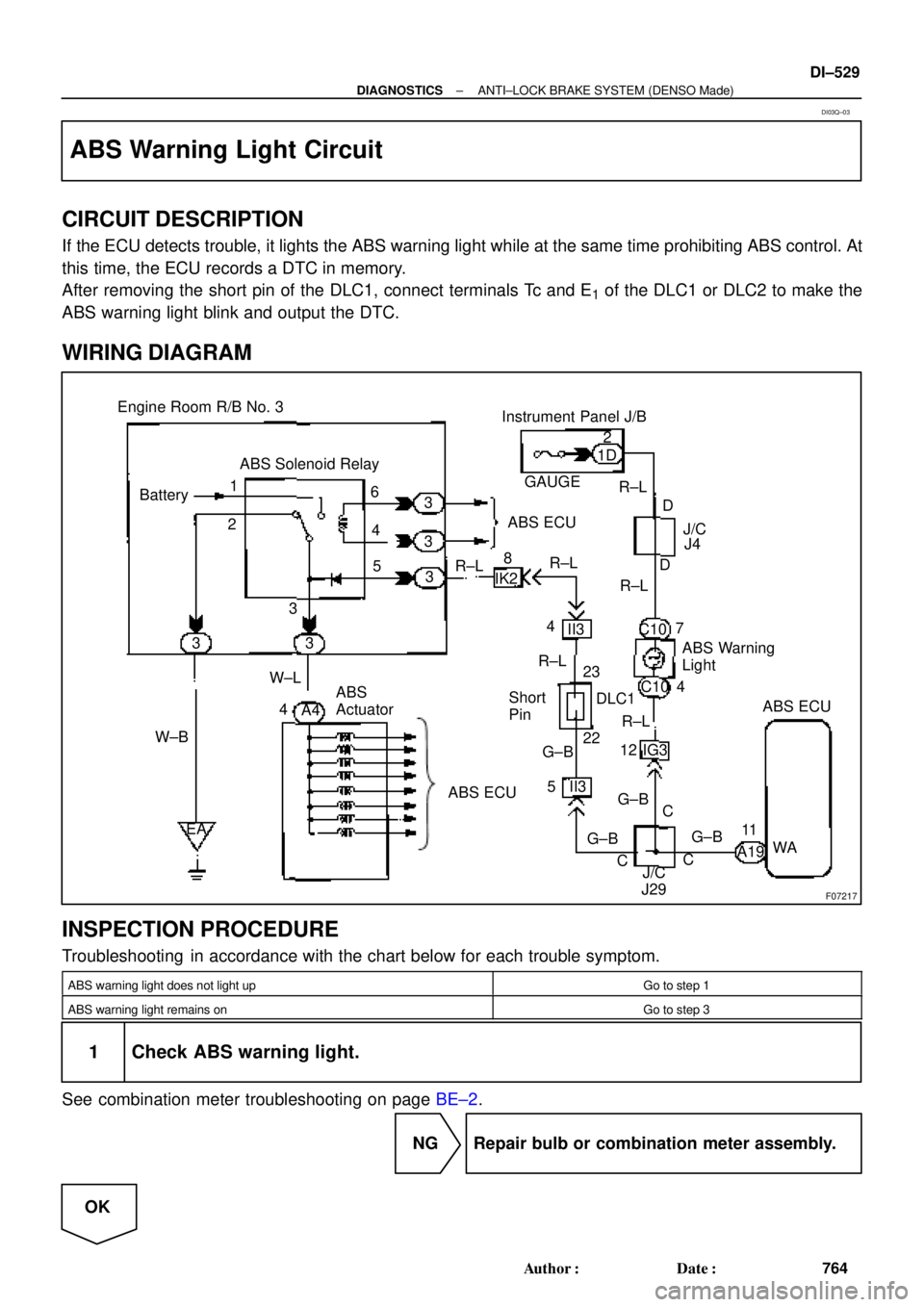
ABS Warning Light Circuit
CIRCUIT DESCRIPTION
If the ECU detects trouble, it lights the ABS warning light while at the same time prohibiting ABS control. At
this time, the ECU records a DTC in memory.
After removing the short pin of the DLC1, connect terminals Tc and E
1 of the DLC1 or DLC2 to make the
ABS warning light blink and output the DTC.
WIRING DIAGRAM
INSPECTION PROCEDURE
Troubleshooting in accordance with the chart below for each trouble symptom.
ABS warning light does not light upGo to step 1
ABS warning light remains onGo to step 3
1 Check ABS warning light.
See combination meter troubleshooting on page BE±2.
NG Repair bulb or combination meter assembly.
OK
DI03Q±03
Page 2981 of 4770
F00125
MAIN
Battery ALT F4B±R
F91B
1C
STOP
B±G4
1 Instrument Panel J/B
FL Block
1 7 WA6
21S 5IK3 J28
G±WECU
J27
1RSTP
Stop Light SwitchJ/C
7
G±R
H10Light Failure
Sensor R
W±B A
R9 R11 C14
BP BL 11R
2
4
G±W G±W G±WG±W 1
Instrument
Panel J/B
2 1
G±RG±R
W±B W±B
W±B H10R9
R11
J/C
A A High
Mounted
Stop
LightRight
Stop
LightLeft
Stop
Light
J405 2
12
2
5
W±B
W±B
± DIAGNOSTICSANTI±LOCK BRAKE SYSTEM (BOSCH Made)
DI±561
796 Author�: Date�:
DTC 58 Stop Light Switch Circuit
CIRCUIT DESCRIPTION
DTC No.DTC Detecting ConditionTrouble Area
49
Stop light switch circuit is open, and stop light switch
voltage is in the level between 65 % or more and less
than 93 % of the battery voltage.�Stop light switch
�Stop light switch circuit
�ECU
WIRING DIAGRAM
INSPECTION PROCEDURE
1 Check operation of stop light.
CHECK:
Check that stop light lights up when brake pedal is depressed and turns off when brake pedal is released.
NG Repair stop light circuit (See page BE±36).
OK
DI046±09
Page 2985 of 4770
F00096
J/C
J4 D
ABS 7
C
R±LC10
1D
GAUGE
A6 4
DLC2ECU
Instrument
Panel J/BABS
Warning
Light
210
IG312
C10
DR±L R±L
WA 21
14 R±LJ/C
J29
C
C R±L
R±LR±L
IK3
± DIAGNOSTICSANTI±LOCK BRAKE SYSTEM (BOSCH Made)
DI±565
800 Author�: Date�:
ABS Warning Light Circuit
CIRCUIT DESCRIPTION
If the ECU detects any trouble, it lights the ABS warning light while at the same time prohibiting ABS control.
At this time, the ECU records a DTC in memory.
Connect terminals Tc and E
1 of the DLC1 or DLC2 to make the ABS warning light blink and output the DTC.
WIRING DIAGRAM
INSPECTION PROCEDURE
Troubleshoot in accordance with the chart below for each trouble symptom
ABS warning light does not light upGo to step 1
ABS warning light remains onGo to step 2
1 Check ABS warning light.
See combination meter troubleshooting on page BE±2.
NG Repair bulb or combination meter assembly.
OK
Check for open circuit in harness and connector between GAUGE fuse, DLC2 and ABS ECU
(See page IN±31).
DI048±08
Page 3032 of 4770

F00168
BatteryABS & TRAC
Solenoid Relay Engine Room R/B No. 3
3ABS & TRAC
ECU
A8 1
R±L
C 5 4
IG3 IK2 6
J/C C10
EA4ABS Warning Light 8
12 II3
G±B23 2
22 ABS & TRAC
Actuator
DLC1 Short
Pin
WA
J29 33 3 3
3
W±B4
ABS & TRAC
ECUR±L
4
R±L
II3 5
G±B
C C G±B R±LC107
ABS & TRAC ECU R±LR±L
J/C
D 1D
GAUGE Instrument Panel J/B
A16 J4 D
G±B4 W±L
2
DI±612
± DIAGNOSTICSABS & TRACTION CONTROL SYSTEM
847 Author�: Date�:
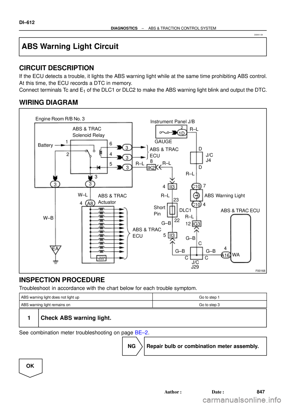
ABS Warning Light Circuit
CIRCUIT DESCRIPTION
If the ECU detects a trouble, it lights the ABS warning light while at the same time prohibiting ABS control.
At this time, the ECU records a DTC in memory.
Connect terminals Tc and E
1 of the DLC1 or DLC2 to make the ABS warning light blink and output the DTC.
WIRING DIAGRAM
INSPECTION PROCEDURE
Troubleshoot in accordance with the chart below for each trouble symptom.
ABS warning light does not light upGo to step 1
ABS warning light remains onGo to step 3
1 Check ABS warning light.
See combination meter troubleshooting on page BE±2.
NG Repair bulb or combination meter assembly.
OK
DI04V±04
Page 3037 of 4770

F00114
TRAC OFF
Indicator LightABS & TRAC ECU
CJ32 C10 R±L7
DLC2
17 J/CJ/C
2
IG3
TRC
Instrument Panel J/B
1D
J4 D319
L
A16
D R±L
C10LL
L
A16 TRAC Cut Switch
W±B12
11
LGWT
CSW
J7
J114 1
IGJ8
A 8
1JW±B
A J/C
1J7 Instrument Panel J/B
W±B
A J/CTRAC OFF
Indicator LightABS & TRAC ECU
C
C10 R±L7
DLC2
17 J/CJ/C
2
IG3
TRC
Instrument Panel J/B
1D
J4 D319
L
A16
D R±L
C10LL
L
A16 TRAC Cut Switch
W±B12
11
LGWT
CSW
J7
J114 1
IGJ8
A 8
1JW±B
A J/C
1J7 Instrument Panel J/B
W±B
A J/CTRAC OFF
Indicator LightABS & TRAC ECU
C
C10 R±L7
DLC2
17 J/CJ/C
2
IG3
TRC
Instrument Panel J/B
1D
J4 D319
L
A16
D R±L
C10LL
L
A16 TRAC Cut Switch
W±B12
11
LGWT
CSW
J7
J114 1
IGJ8
A 8
1JW±B
A J/C
1J7 Instrument Panel J/B
W±B
A J/CTRAC OFF
Indicator LightABS & TRAC ECU
C10 R±L7
DLC2
17 J/CJ/C
2
IG3
TRC
Instrument Panel J/B
1D
J4 D319
L
A16
D R±L
C10LL
L
A16 TRAC Cut Switch
W±B12
11
LGWT
CSW
J7
J114 1
IGJ8
A 8
1JW±B
A J/C
1J7 Instrument Panel J/B
W±B
A J/C
TRAC OFF
Indicator LightABS & TRAC ECU
C10
GAUGER±L7
DLC2
17 J/CJ/C
2
IG3
TRC
Instrument Panel J/B
1D
J4 D319
L
A16
D R±L
C10LL
L
A16 TRAC Cut Switch
W±B12
11
LGWT
CSW
J7
J114 1
IGJ8
A 8
1JW±B
A J/C
1J7 Instrument Panel J/B
W±B
A J/CJ32 J32
± DIAGNOSTICSABS & TRACTION CONTROL SYSTEM
DI±617
852 Author�: Date�:
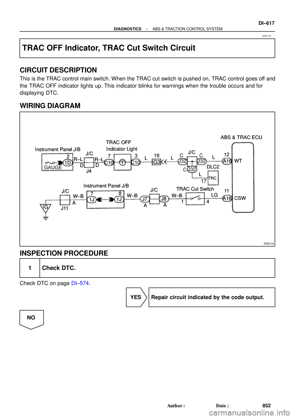
TRAC OFF Indicator, TRAC Cut Switch Circuit
CIRCUIT DESCRIPTION
This is the TRAC control main switch. When the TRAC cut switch is pushed on, TRAC control goes off and
the TRAC OFF indicator lights up. This indicator blinks for warnings when the trouble occurs and for
displaying DTC.
WIRING DIAGRAM
INSPECTION PROCEDURE
1 Check DTC.
Check DTC on page DI±574.
YES Repair circuit indicated by the code output.
NO
DI04Y±04