Page 2115 of 4770

± BODY ELECTRICALIGNITION SWITCH AND KEY UNLOCK WARNING
SWITCHBE±21
2241 Author�: Date�:
Tester connectionConditionSpecified condition
A1 ± GroundDoor lock manual switch OFF or UNLOCKNo continuity
A1 ± GroundDoor lock manual switch LOCKContinuity
A2 ± GroundDoor lock manual switch OFF or LOCKNo continuity
A2 ± GroundDoor lock manual switch UNLOCKContinuity
A3 ± GroundDriver's and passenger's door key lock and
unlock switch OFF or UNLOCKNo continuity
A3 ± GroundDriver's or passenger's door key lock and unlock
switch LOCKContinuity
A4 ± GroundDriver's door key lock and unlock switch OFF or
LOCKNo continuity
A4 ± GroundDriver's door key lock and unlock switch
UNLOCKContinuity
A5 ± GroundPassenger's door key lock and unlock switch
OFF or LOCKNo continuity
A5 ± GroundPassenger's door key lock and unlock switch
UNLOCKContinuity
A6 ± A7ConstantContinuity
A8 ± GroundPassenger's door courtesy switch OFF (Door
closed)No continuity
A8 ± GroundPassenger's door courtesy switch ON (Door
opened)Continuity
A9 ± GroundDriver's door unlock detection switch OFF (Door
closed)No continuity
A9 ± GroundDriver's door unlock detection switch ON (Door
opened)Continuity
A10 ± GroundPassenger's door unlock detection switch OFF
(Door closed)No continuity
A10 ± GroundPassenger's door unlock detection switch ON
(Door opened)Continuity
A11 ± GroundRear door unlock detection switch OFF (Door
closed)No continuity
A11 ± GroundRear door unlock detection switch ON (Door
opened)Continuity
A12 ± GroundConstantContinuity
A13 ± GroundConstantBattery positive voltage
B1 ± GroundLight control switch OFFNo voltage
B1 ± GroundLight control switch TAIL or HEADBattery positive voltage
B4 ± GroundLight control switch OFF or TAILNo voltage
B4 ± GroundLight control switch HEADBattery positive voltage
B2 ± Ground
B3 ± GroundConstantBattery positive voltage
If the circuit is as specified, try replacing the relay with a new
one.
If the circuit is not as specified, inspect the circuits connected
to other parts.
Page 2119 of 4770

CIRCUIT
Disconnect the connector from the relay a")
I08219
Wire harness side:
± BODY ELECTRICALHEADLIGHT AND TAILLIGHT SYSTEM
BE±25
2245 Author�: Date�:
6. INSPECT DAYTIME RUNNING LIGHT RELAY (MAIN)
CIRCUIT
Disconnect the connector from the relay and inspect the con-
nector on the wire harness side.
Tester connectionConditionSpecified condition
2 ± GroundLight control switch position OFF or TAILNo continuity
2 ± GroundLight control switch position HEADContinuity
3 ± GroundHeadlight dimmer switch position
Low beamNo continuity
3 ± GroundHeadlight dimmer switch position
High beam of FlashContinuity
4 ± GroundBrake fluid level warning position OFFNo continuity
4 ± GroundBrake fluid level warning position ONContinuity
12 ± GroundConstantContinuity
14 ± GroundParking brake switch position OFF
(Parking brake lever released)No continuity
14 ± GroundParking brake switch position ON
(Parking brake lever pulled up)Continuity
17 ± GroundLight control switch position OFF or HEADNo voltage
17 ± GroundLight control switch position TAILContinuity
20 ± GroundConstantContinuity
21 ± GroundConstantContinuity
13 ± GroundEngine StopNo voltage
13 ± GroundEngine RunningBattery positive voltage
16 ± GroundConstantBattery positive voltage
18 ± GroundGround terminal 19Battery positive voltage
19 ± GroundConstantBattery positive voltage
22 ± GroundConstantBattery positive voltage
23 ± GroundIgnition switch position LOCK or ACCNo voltage
23 ± GroundIgnition switch position ON or STARTBattery positive voltage
If circuit is as specified, try replacing the relay with a new one.
If circuit is not as specified, inspect the circuits connected to oth-
er parts.
Page 2123 of 4770
BE0A8±03
Z19045
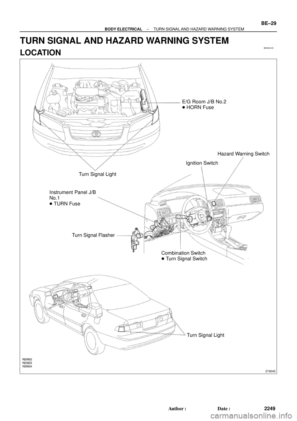
E/G Room J/B No.2
� HORN Fuse
Turn Signal Light
Instrument Panel J/B
No.1
� TURN Fuse
Turn Signal Flasher
Combination Switch
� Turn Signal SwitchIgnition SwitchHazard Warning Switch
Turn Signal Light
± BODY ELECTRICALTURN SIGNAL AND HAZARD WARNING SYSTEM
BE±29
2249 Author�: Date�:
TURN SIGNAL AND HAZARD WARNING SYSTEM
LOCATION
Page 2124 of 4770

N20140
1 2 3
4
5 6 7 8 9 10
BE±30
± BODY ELECTRICALTURN SIGNAL AND HAZARD WARNING SYSTEM
2250 Author�: Date�:
INSPECTION
1")
BE0A9±02
N20150
Right
Left
2 31
BE1843
1 23
Turn Signal Light Bulbs (21 W)
N20140
1 2 3
4
5 6 7 8 9 10
BE±30
± BODY ELECTRICALTURN SIGNAL AND HAZARD WARNING SYSTEM
2250 Author�: Date�:
INSPECTION
1. INSPECT TURN SIGNAL SWITCH CONTINUITY
Switch positionTester connectionSpecified condition
Left turn1 ± 2Continuity
Neutral±No continuity
Right turn2 ± 3Continuity
If continuity is not as specified, replace the switch.
2. INSPECT TURN SIGNAL FLASHER OPERATION
(a) Connect the positive (+) lead from the battery to terminal
2 and the negative (±) lead to terminal 3.
(b) Connect the 2 turn signal light bulbs in parallel to each
other to terminals 1 and 3, check that the bulbs flash.
HINT:
The turn signal lights should flash 60 to 120 times per minute.
If one of the front or rear turn signal lights has an open circuit,
the number of flashes will be more than 140 per minute.
If operation is not as specified, replace the flasher.
3. INSPECT HAZARD WARNING SWITCH CONTINUITY
Switch positionTester connectionSpecified condition
Switch OFF7 ± 10Continuity
Switch ON5 ± 6 ± 9
7 ± 8Continuity
Illumination circuit2 ± 3Continuity
If continuity is not as specified, replace the switch.
Page 2138 of 4770
BE0AI±03
Z19050
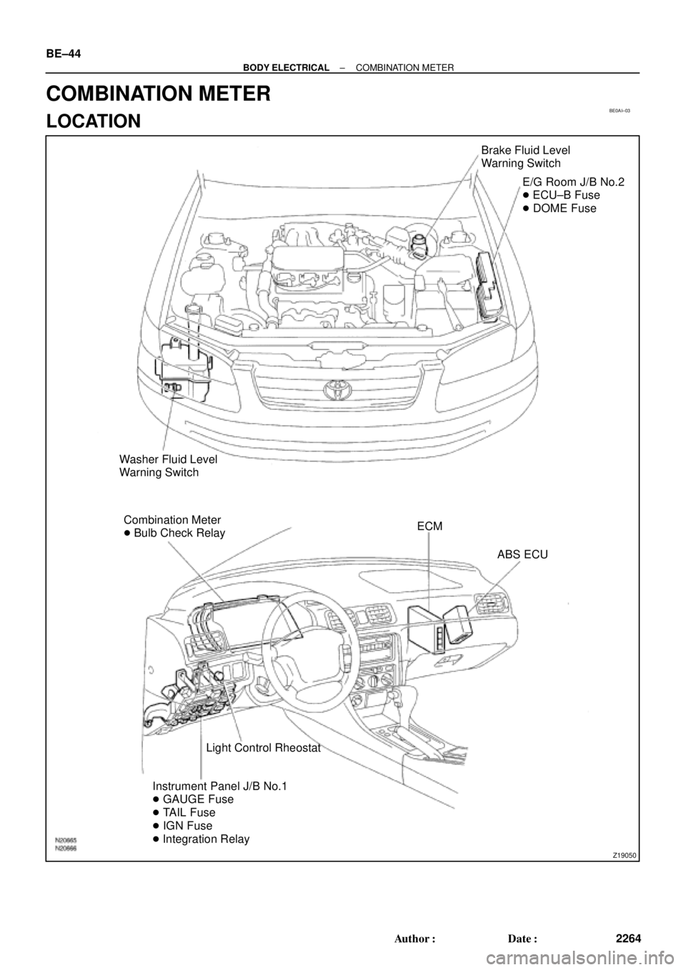
Brake Fluid Level
Warning Switch
E/G Room J/B No.2
� ECU±B Fuse
� DOME Fuse
Washer Fluid Level
Warning Switch
Combination Meter
� Bulb Check RelayECM
ABS ECU
Light Control Rheostat
Instrument Panel J/B No.1
� GAUGE Fuse
� TAIL Fuse
� IGN Fuse
� Integration Relay BE±44
± BODY ELECTRICALCOMBINATION METER
2264 Author�: Date�:
COMBINATION METER
LOCATION
Page 2139 of 4770
Z19055
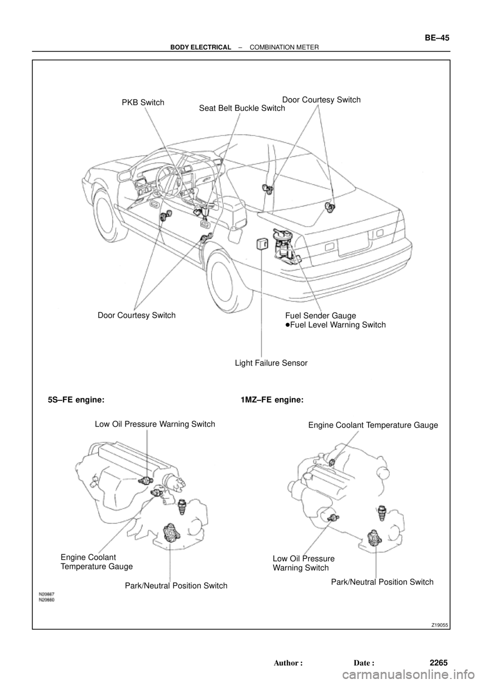
PKB Switch
Seat Belt Buckle SwitchDoor Courtesy Switch
Door Courtesy Switch
Light Failure SensorFuel Sender Gauge
�Fuel Level Warning Switch
5S±FE engine: 1MZ±FE engine:
Low Oil Pressure Warning Switch
Engine Coolant Temperature Gauge
Engine Coolant
Temperature Gauge
Park/Neutral Position SwitchLow Oil Pressure
Warning Switch
Park/Neutral Position Switch
± BODY ELECTRICALCOMBINATION METER
BE±45
2265 Author�: Date�:
Page 2140 of 4770

BE0AJ±03
Z18937
Connector ºAº Connector ºBº Connector ºCº
Connector ºAº
Connector ºBº
Connector ºCº
J±13±1±A J±16±1 J±13±1
1 2 3 4 5 6 7 8 9 10 11 12 1314 15 16 1 234 56 78 910111213 1 23456 78910111213
C7
C5
A2 B3
A1
C8
B15
C6
B6
A4
C4
B5
C10 B14
A13
B2
C1
B1
C9
A6
A11
A7
A10
A8
A9
C13
B8
B11
B12A5
C11
B4
B16 C2
A12
A3
B7
C3
C12
B9
B10
B13 F
E
T
S
ODOMETER
Fuel Level Warning
Seat Belt Warning
ABS Warning
Low Oil Pressure Warning
Cruise Control Indicator
Malfunction Indicator
O/D OFF Indicator
Light Failure Warning
Brake Warning
SLIP Indicator
TRAC Indicator
Washer Level Warning
Discharge Warning
Right Turn Indicator
Left Turn Indicator
Security Indicator
L
2
D
N
R
P
Illumination
Hi±Beam Indicator
Open Door Warning
SRS Warning
: Fuel Gauge
: Engine Coolant Temperature Gauge
: Tachometer
: Speedometer
No.
A
B
C1
2
3
4
5
6
7 8
9
10
11
12 13
14
15
16
2 3
4
5
6
7 8
9
10
11 12
131
2
3
4 5
6
7
8
9
10
11
12
13
F
E
T
SEngine coolant temperature sender gauge
Ground
Light failure sensor
Integration relay
Traction ECU
Park/neutral position switch (A/T)
O/D OFF switch (A/T)
IGN fuse
Turn signal switch
ST relay
Fuel sender gauge
Generator
Oil pressure switch
Fuel sender gauge
Parking brake switch and brake fluid level warning switch
Headlight dimmer switch
Headlight dimmer switch
Door courtesy switch
DOME fuse
ECU±B fuse
Airbag sensor assembly
ECM
No.1 Vehicle speed sensor Ground
Turn signal switch ECM
Traction ECU
ABS ECU
Ground No.1 Vehicle speed sensor
GAUGE fuse
Igniter
Security ECU
Cruise control ECU
Washer fluid level warning switch
Light control rheostat
TAIL fuse Park/neutral position switch (A/T) Park/neutral position switch (A/T) Park/neutral position switch (A/T) Park/neutral position switch (A/T)
Park/neutral position switch (A/T)Wire Harness Side
Bulb Check
Relay
N20107 N201081
BE±46
± BODY ELECTRICALCOMBINATION METER
2266 Author�: Date�:
CIRCUIT
Page 2143 of 4770

N20161
F
1/2
E1
2 3
Z05730 1
3
42
5
BE1217 Ie±5±1±A
BatteryWarning Light
Ignition
Switch
N20213
1 3
N20214
1
3
N20215
Engine coolant temperature gauge
Ignition
Switch
BatterySender
Gauge
± BODY ELECTRICALCOMBINATION METER
BE±49
2269 Author�: Date�:
6. INSPECT FUEL SENDER GAUGE RESISTANCE
Measure the resistance between terminals 2 and 3 for each
float position.
Float position mm (in.)Resistance (W)
F: Approx. ±91.1 (±3.587)Approx. 3.0
1/2: Approx. ±34.2 (±1.346)Approx. 31.7
E: Approx. 30.8 (1.213)Approx. 110.0
If resistance value is not as specified, replace the sender
gauge.
7. INSPECT FUEL LEVEL WARNING LIGHT
(a) Disconnect the connector from the sender gauge.
(b) Connect terminals 1 and 3 on the wire harness side con-
nector.
(c) Turn the ignition switch ON, check that the warning light
lights up.
If the warning light does not light up, test the bulb or inspect wire
harness.
8. INSPECT FUEL LEVEL WARNING SWITCH
(a) Apply battery positive voltage between terminals 1 and 3
through a 3.4±W test bulb, check that the bulb lights up.
HINT:
It takes a short time for the bulb to light up.
(b) Submerge the switch in fuel, check that the bulb goes out.
If operation is not as specified, replace the sender gauge.
9. INSPECT ENGINE COOLANT TEMPERATURE RE-
CEIVER GAUGE OPERATION
(a) Disconnect the connector from the sender gauge.
(b) Turn the ignition switch ON and check that the receiver
gauge needle indicates COOL.