Page 4372 of 4770
SA07L±01
SA±32
± SUSPENSION AND AXLEFRONT DRIVE SHAFT (1MZ±FE)
1983 Author�: Date�:
INSTALLATION
Installation is in the reverse order of removal (See page SA±26).
AFTER INSTALLATION, CHECK ABS SPEED SENSOR SIGNAL (See page DI±493 or DI±539) AND
FRONT WHEEL ALIGNMENT (See page SA±4)
Page 4373 of 4770
SA07M±05
F06530
Suspension Support
Spring Bumper
Link Stabilizer Bar
Shock
Absorber
ABS Speed Sensor
Wire Harness ClampFront Drive Shaft with Coil SpringUpper Seat Bearing
Lower
Insulator
Lower Suspension Arm Lower Suspension
Bushing StopperBrake CaliperInsulator UpperSpring Support No. 2Suspension
Shock Absorber
Coil Spring
Tie Rod End
� Dust
Deflector
� Cotter Pin
� Cotter Pin� Cotter
Pin
Lower Ball jointDisc
Lock Cap ABS Speed Sensor
N´m (kgf´cm, ft´lbf): Specified torque
� Non±reusable part�
80 (820, 59)49 (500, 36)
39 (400, 29)
211 (2,150, 156)
107 (1,090, 79)
29 (300, 22)
123 (1,250, 90)49 (500, 36)
8.0 (82, 71 in.´lbf)
294 (3,000, 217)
206 (2,100, 152)
206 (2,100, 152)
206 (2,100, 152)
127 (1,300, 94)
127 (1,300, 94)
± SUSPENSION AND AXLEFRONT SHOCK ABSORBER
SA±33
1984 Author�: Date�:
FRONT SHOCK ABSORBER
COMPONENTS
Page 4380 of 4770
SA07T±04
F06530
Suspension Support
Spring Bumper
Link Stabilizer Bar
Shock
Absorber
ABS Speed Sensor
Wire Harness ClampFront Drive Shaft with Coil SpringUpper Seat Bearing
Lower
Insulator
Lower Suspension Arm Lower Suspension
Bushing StopperBrake CaliperInsulator UpperSpring Support No. 2Suspension
Shock Absorber
Coil Spring
Tie Rod End
� Dust
Deflector
� Cotter Pin
� Cotter Pin� Cotter
Pin
Lower Ball jointDisc
Lock Cap ABS Speed Sensor
N´m (kgf´cm, ft´lbf): Specified torque
� Non±reusable part�
80 (820, 59)49 (500, 36)
39 (400, 29)
211 (2,150, 156)
107 (1,090, 79)
29 (300, 22)
123 (1,250, 90)49 (500, 36)
8.0 (82, 71 in.´lbf)
294 (3,000, 217)
206 (2,100, 152)
206 (2,100, 152)
206 (2,100, 152)
127 (1,300, 94)
127 (1,300, 94)
SA±40
± SUSPENSION AND AXLEFRONT LOWER SUSPENSION ARM
1991 Author�: Date�:
FRONT LOWER SUSPENSION ARM
COMPONENTS
Page 4383 of 4770
SA07X±05
F06530
Suspension Support
Spring Bumper
Link Stabilizer Bar
Shock
Absorber
ABS Speed Sensor
Wire Harness ClampFront Drive Shaft with Coil SpringUpper Seat Bearing
Lower
Insulator
Lower Suspension Arm Lower Suspension
Bushing StopperBrake CaliperInsulator UpperSpring Support No. 2Suspension
Shock Absorber
Coil Spring
Tie Rod End
� Dust
Deflector
� Cotter Pin
� Cotter Pin� Cotter
Pin
Lower Ball jointDisc
Lock Cap ABS Speed Sensor
N´m (kgf´cm, ft´lbf): Specified torque
� Non±reusable part�
80 (820, 59)49 (500, 36)
39 (400, 29)
211 (2,150, 156)
107 (1,090, 79)
29 (300, 22)
123 (1,250, 90)49 (500, 36)
8.0 (82, 71 in.´lbf)
294 (3,000, 217)
206 (2,100, 152)
206 (2,100, 152)
206 (2,100, 152)
127 (1,300, 94)
127 (1,300, 94)
± SUSPENSION AND AXLEFRONT LOWER BALL JOINT
SA±43
1994 Author�: Date�:
FRONT LOWER BALL JOINT
COMPONENTS
Page 4386 of 4770
SA080±01
R08850
R08861
SST
SST SA±46
± SUSPENSION AND AXLEFRONT LOWER BALL JOINT
1997 Author�: Date�:
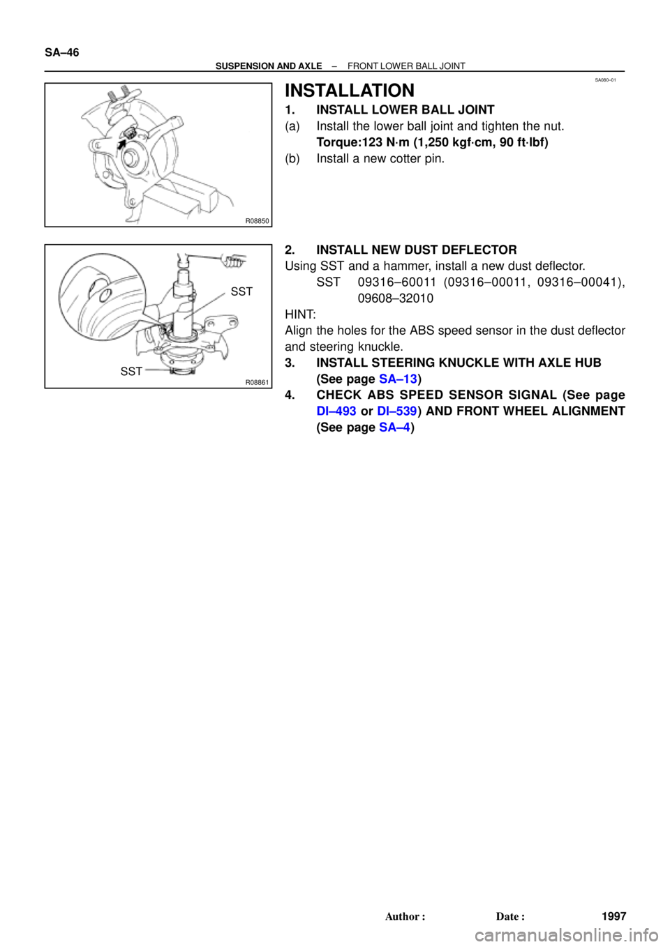
INSTALLATION
1. INSTALL LOWER BALL JOINT
(a) Install the lower ball joint and tighten the nut.
Torque:123 N´m (1,250 kgf´cm, 90 ft´lbf)
(b) Install a new cotter pin.
2. INSTALL NEW DUST DEFLECTOR
Using SST and a hammer, install a new dust deflector.
SST 09316±60011 (09316±00011, 09316±00041),
09608±32010
HINT:
Align the holes for the ABS speed sensor in the dust deflector
and steering knuckle.
3. INSTALL STEERING KNUCKLE WITH AXLE HUB
(See page SA±13)
4. CHECK ABS SPEED SENSOR SIGNAL (See page
DI±493 or DI±539) AND FRONT WHEEL ALIGNMENT
(See page SA±4)
Page 4391 of 4770
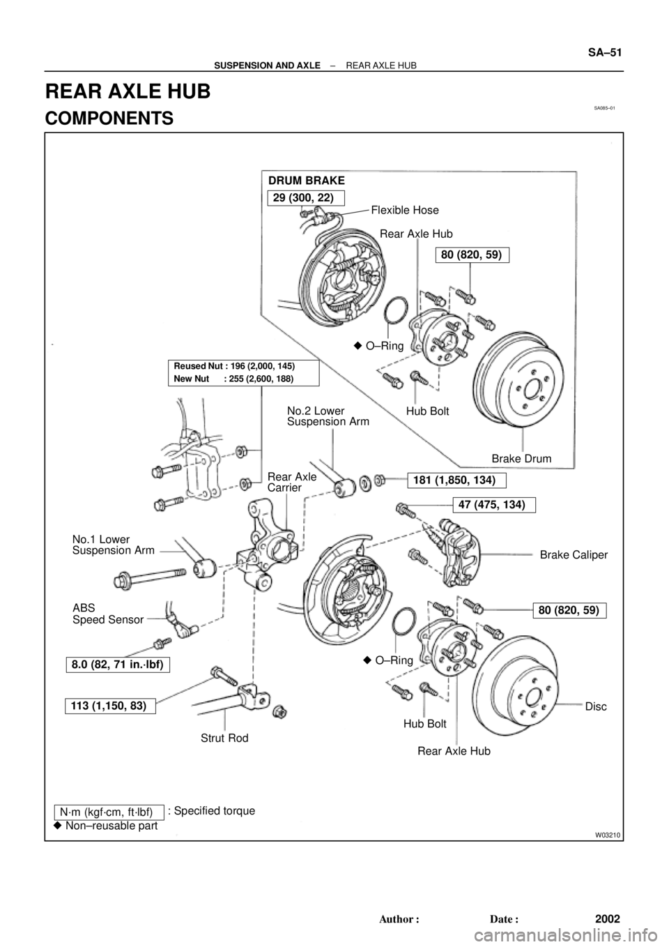
SA085±01
W03210
DRUM BRAKE
Flexible Hose
Rear Axle Hub
� O±Ring
Hub Bolt
Brake Drum
Brake Caliper No.2 Lower
Suspension Arm
Rear Axle
Carrier
No.1 Lower
Suspension Arm
� O±Ring
Hub Bolt
Rear Axle HubDisc ABS
Speed Sensor
Strut Rod
N´m (kgf´cm, ft´lbf)
� Non±reusable part: Specified torque
181 (1,850, 134)
47 (475, 134)
80 (820, 59)
113 (1,150, 83)
29 (300, 22)
80 (820, 59)
Reused Nut : 196 (2,000, 145)
New Nut : 255 (2,600, 188)
8.0 (82, 71 in.´lbf)
± SUSPENSION AND AXLEREAR AXLE HUB
SA±51
2002 Author�: Date�:
REAR AXLE HUB
COMPONENTS
Page 4393 of 4770
 w/ Drum brake:
Remove the bolt, and disconnect the flexible hose from
the shock absorber.
Torque: 29 N´m (300")
A
B
A
W03211
R11165
± SUSPENSION AND AXLEREAR AXLE HUB
SA±53
2004 Author�: Date�:
(c) w/ Drum brake:
Remove the bolt, and disconnect the flexible hose from
the shock absorber.
Torque: 29 N´m (300 kgf´cm, 22 ft´lbf)
(d) Support the backing plate securely.
6. w/ ABS:
REMOVE ABS SPEED SENSOR
Torque: 8.0 N´m (82 kgf´cm, 71 in.´lbf)
7. REMOVE REAR AXLE CARRIER
(a) Loosen the 3 nuts.
Torque:
Nut A:
Reused nut: 196 N´m (2,000 kgf´cm, 145 ft´lbf)
New nut: 255 N´m (2,600 kgf´cm, 188 ft´lbf)
Nut B: 181 N´m (1,850 kgf´cm, 134 ft´lbf)
HINT:
At the time of installation, please refer to the following items.
�If reusing the 2 nuts, coat the nut's threads with en-
gine oil.
�After stabilizing the suspension, torque the nuts.
(b) Remove the bolt and nut, and disconnect the strut rod
from the rear axle carrier.
NOTICE:
When removing/installing bolt, stop the nut from rotating
and loosen/torque the bolt.
Torque: 113 N´m (1,150 kgf´cm, 83 ft´lbf)
(c) Remove the 2 nuts and bolts on the lower side of the
shock absorber.
(d) Remove the nut, bolt and No.2 lower suspension arm.
(e) Remove the rear axle carrier.
Page 4394 of 4770
SA087±01
SA±54
± SUSPENSION AND AXLEREAR AXLE HUB
2005 Author�: Date�:
INSTALLATION
Installation is in the reverse order of removal (See page SA±52).
AFTER INSTALLATION, CHECK ABS SPEED SENSOR SIGNAL (See page DI±493 or DI±539) AND
REAR WHEEL ALIGNMENT (See page SA±7)