Page 274 of 447
8-30 BODY ELECTRICAL SYSTEM
RECEIVER
INSPECTION
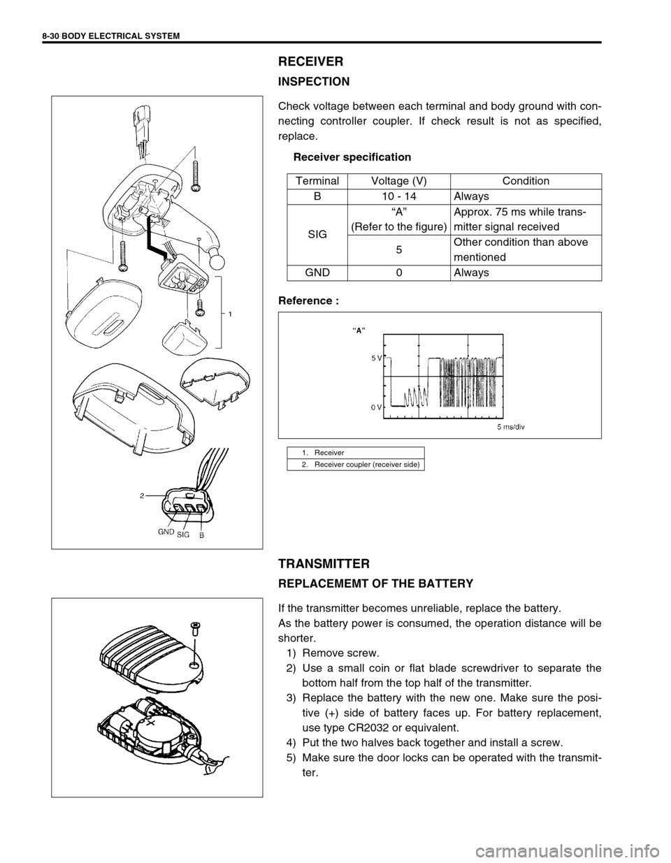
Check voltage between each terminal and body ground with con-
necting controller coupler. If check result is not as specified,
replace.
Receiver specification
Reference :
TRANSMITTER
REPLACEMEMT OF THE BATTERY
If the transmitter becomes unreliable, replace the battery.
As the battery power is consumed, the operation distance will be
shorter.
1) Remove screw.
2) Use a small coin or flat blade screwdriver to separate the
bottom half from the top half of the transmitter.
3) Replace the battery with the new one. Make sure the posi-
tive (+) side of battery faces up. For battery replacement,
use type CR2032 or equivalent.
4) Put the two halves back together and install a screw.
5) Make sure the door locks can be operated with the transmit-
ter. Terminal Voltage (V) Condition
B10 - 14Always
SIG“A”
(Refer to the figure)Approx. 75 ms while trans-
mitter signal received
5Other condition than above
mentioned
GND 0 Always
1. Receiver
2. Receiver coupler (receiver side)
Page 275 of 447
BODY ELECTRICAL SYSTEM 8-31
CODE REGISTRATION PROCEDURE
1) Confirm that IG switch is OFF position.
2) Remove DOOR LOCK fuse and install it again.
3) Press the button on the transmitter one time toward the
receiver within 30 seconds.
4) If two transmitters are registered, repeat step 1) to 3) with
other transmitter.
POWER DOOR MIRROR CONTROL SYSTEM
(IF EQUIPPED)
MIRROR SWITCH
INSPECTION
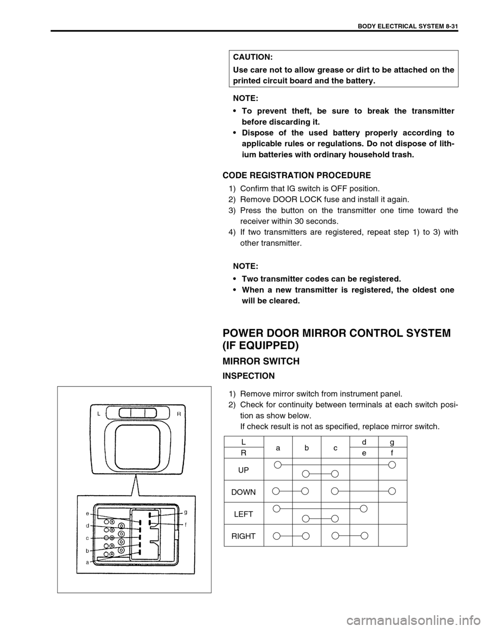
1) Remove mirror switch from instrument panel.
2) Check for continuity between terminals at each switch posi-
tion as show below.
If check result is not as specified, replace mirror switch. CAUTION:
Use care not to allow grease or dirt to be attached on the
printed circuit board and the battery.
NOTE:
To prevent theft, be sure to break the transmitter
before discarding it.
Dispose of the used battery properly according to
applicable rules or regulations. Do not dispose of lith-
ium batteries with ordinary household trash.
NOTE:
Two transmitter codes can be registered.
When a new transmitter is registered, the oldest one
will be cleared.
UP
DOWN
LEFT
RIGHTL
Rabcd
eg
f
Page 276 of 447
8-32 BODY ELECTRICAL SYSTEM
DOOR MIRROR ACTUATOR
INSPECTION
1) Remove garnish from door.
2) Pull out door mirror coupler at bracket.
3) Disconnect door mirror coupler.
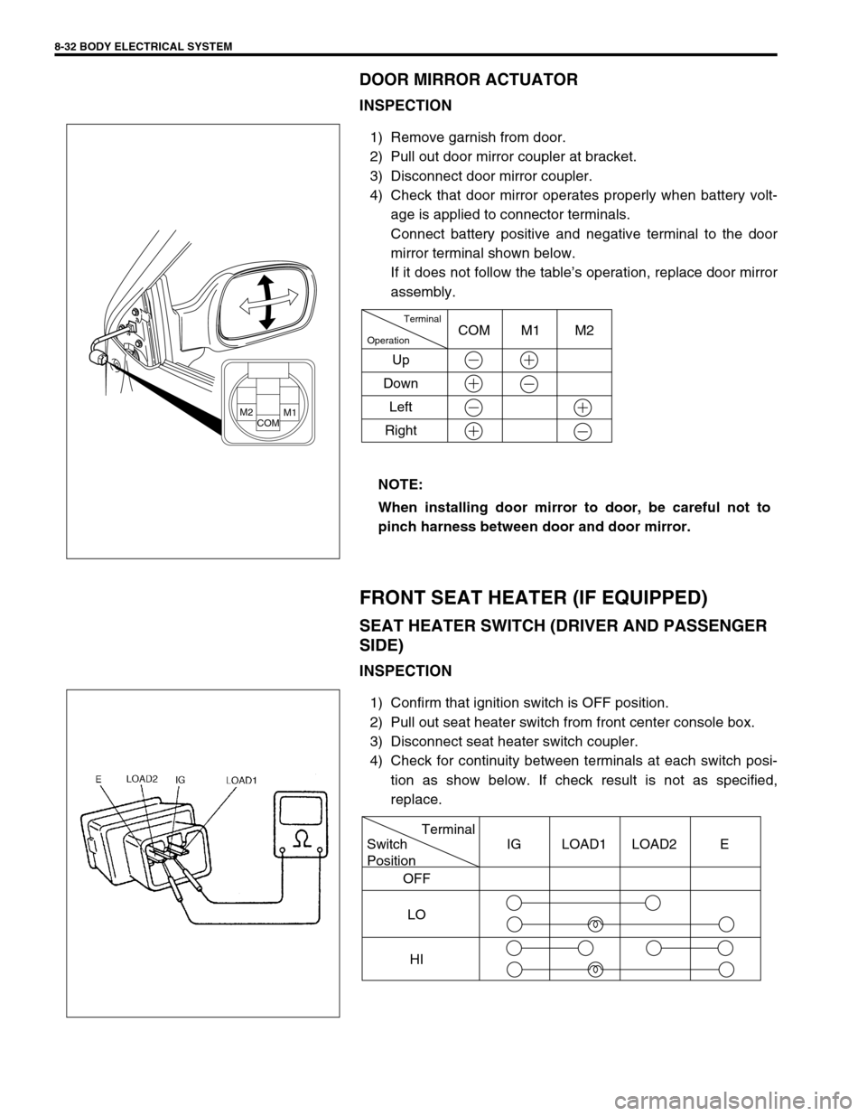
4) Check that door mirror operates properly when battery volt-
age is applied to connector terminals.
Connect battery positive and negative terminal to the door
mirror terminal shown below.
If it does not follow the table’s operation, replace door mirror
assembly.
FRONT SEAT HEATER (IF EQUIPPED)
SEAT HEATER SWITCH (DRIVER AND PASSENGER
SIDE)
INSPECTION
1) Confirm that ignition switch is OFF position.
2) Pull out seat heater switch from front center console box.
3) Disconnect seat heater switch coupler.
4) Check for continuity between terminals at each switch posi-
tion as show below. If check result is not as specified,
replace. NOTE:
When installing door mirror to door, be careful not to
pinch harness between door and door mirror.
M2COMM1
Terminal
Operation
UpCOM M1 M2
Down
Left
Right
Terminal
Switch
Position
OFF
LO
HIIG LOAD1 LOAD2 E
Page 277 of 447
BODY ELECTRICAL SYSTEM 8-33
SEAT HEATER WIRE
INSPECTION
1) Confirm that seat heater switch is OFF position.
2) Disconnect two couplers of seat heater under the seat cush-
ion.
3) Check for continuity between terminals as show below.
If not continuity, replace faulty seat heater.
Seat heater circuit in seat back
Between “a” and “b”
Between “b” and “d”
Between “c” and “e”
Seat heater circuit in seat cushion
Between “f” and “g”
1. Heater wire
2. Thermostat
Page 278 of 447
8-34 BODY ELECTRICAL SYSTEM
Page 351 of 447
BODY SERVICE 9-47
IGNITION SWITCH LOCK CYLINDER
REMOVAL AND INSTALLATION
Refer to “STEERING LOCK ASSEMBLY (IGNITION SWITCH)” in
Section 3C.
ELECTRICAL DIAGNOSIS
For ignition switch electrical troubleshooting, refer to “IGNITION
SWITCH” in Section 8.
EXTERIOR AND INTERIOR TRIM
FLOOR CARPET
REMOVAL
1) Remove front seats and rear seat cushion.
2) Remove seat belt lower anchor bolt.
3) Remove dash side trims, front side sill scuffs, center pillar inner lower trims, quarter inner trims and rear side
sill scuffs.
4) Remove parking brake lever cover and console box.
5) Remove floor carpet.
INSTALLATION
Reverse removal sequence to install front floor carpet, noting the following instruction.
For tightening torque of seat belt anchor bolt, refer to “FRONT SEAT BELT” in Section 10.
1. Floor carpet
2. Dash panel silencer
3. Silencer seat
Page 380 of 447
10B-6 AIR BAG SYSTEM
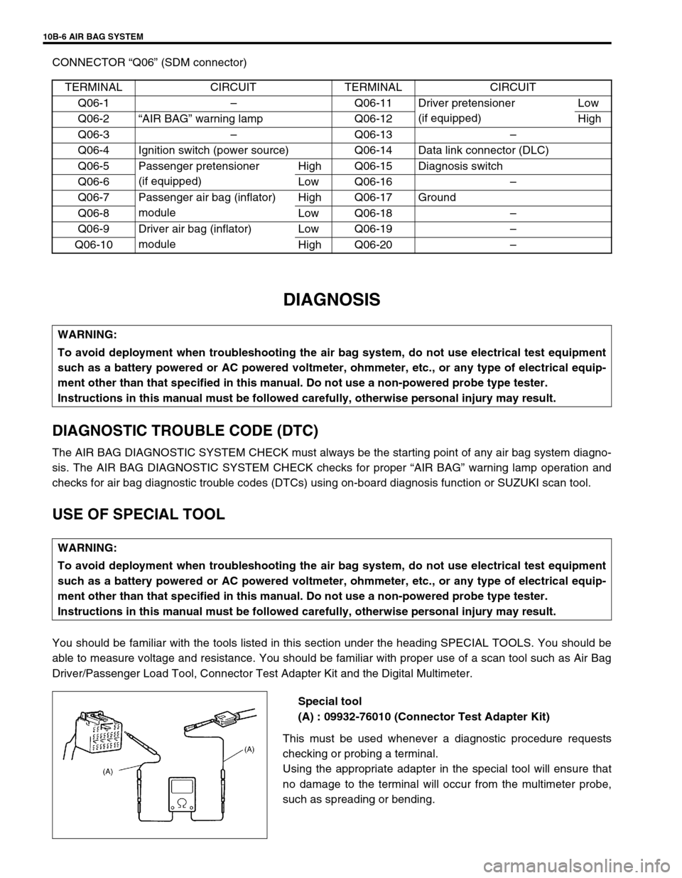
CONNECTOR “Q06” (SDM connector)
DIAGNOSIS
DIAGNOSTIC TROUBLE CODE (DTC)
The AIR BAG DIAGNOSTIC SYSTEM CHECK must always be the starting point of any air bag system diagno-
sis. The AIR BAG DIAGNOSTIC SYSTEM CHECK checks for proper “AIR BAG” warning lamp operation and
checks for air bag diagnostic trouble codes (DTCs) using on-board diagnosis function or SUZUKI scan tool.
USE OF SPECIAL TOOL
You should be familiar with the tools listed in this section under the heading SPECIAL TOOLS. You should be
able to measure voltage and resistance. You should be familiar with proper use of a scan tool such as Air Bag
Driver/Passenger Load Tool, Connector Test Adapter Kit and the Digital Multimeter.
Special tool
(A) : 09932-76010 (Connector Test Adapter Kit)
This must be used whenever a diagnostic procedure requests
checking or probing a terminal.
Using the appropriate adapter in the special tool will ensure that
no damage to the terminal will occur from the multimeter probe,
such as spreading or bending. TERMINAL CIRCUIT TERMINAL CIRCUIT
Q06-1–Q06-11 Driver pretensioner
(if equipped)Low
Q06-2“AIR BAG” warning lamp Q06-12 High
Q06-3–Q06-13–
Q06-4 Ignition switch (power source) Q06-14 Data link connector (DLC)
Q06-5 Passenger pretensioner
(if equipped)High Q06-15 Diagnosis switch
Q06-6 Low Q06-16–
Q06-7 Passenger air bag (inflator)
moduleHigh Q06-17 Ground
Q06-8 Low Q06-18–
Q06-9 Driver air bag (inflator)
moduleLow Q06-19–
Q06-10 High Q06-20–
WARNING:
To avoid deployment when troubleshooting the air bag system, do not use electrical test equipment
such as a battery powered or AC powered voltmeter, ohmmeter, etc., or any type of electrical equip-
ment other than that specified in this manual. Do not use a non-powered probe type tester.
Instructions in this manual must be followed carefully, otherwise personal injury may result.
Page 381 of 447
AIR BAG SYSTEM 10B-7
The adapter will also give an idea of whether contact tension is
sufficient, helping to find an open or intermittent open due to poor
terminal contact.
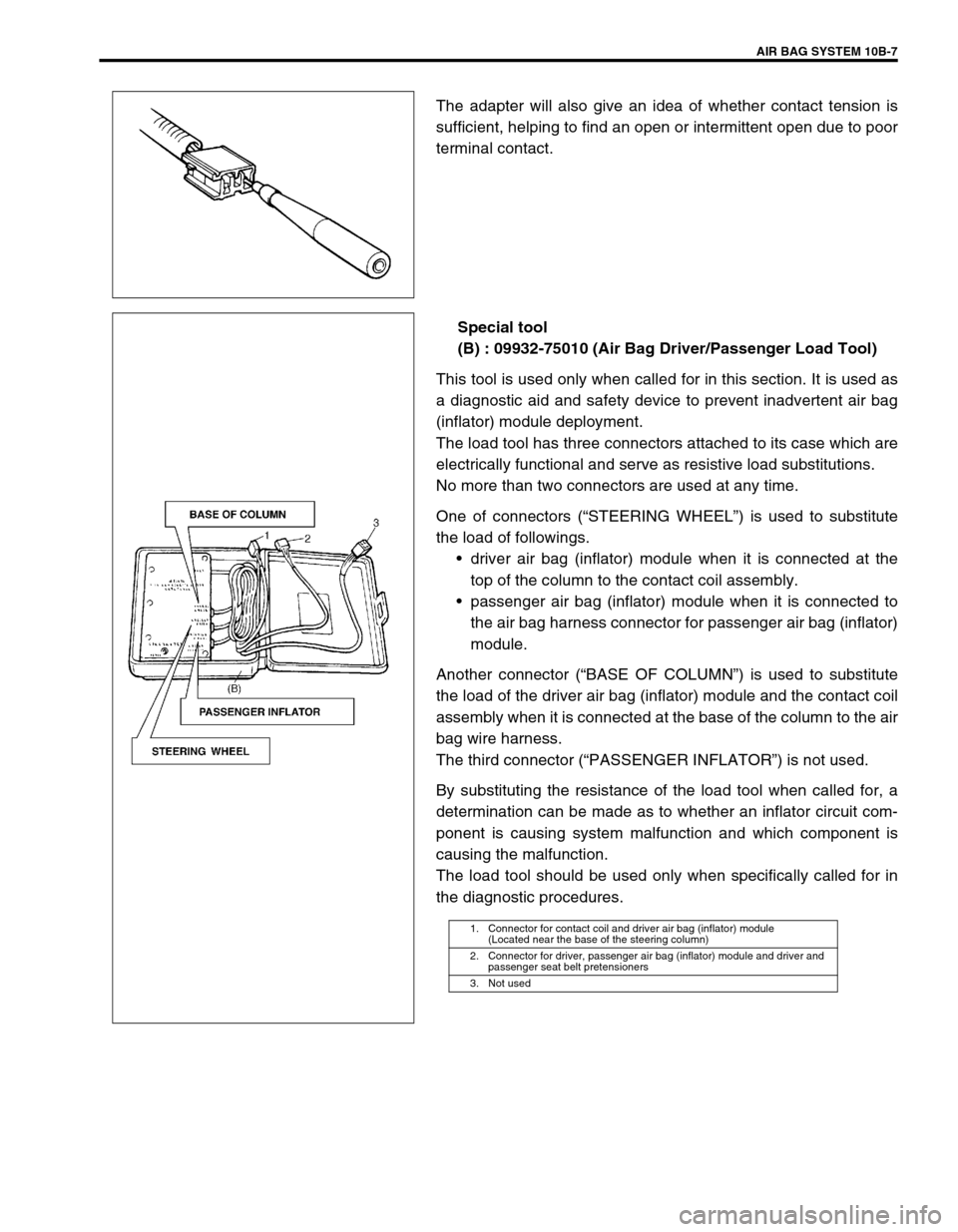
Special tool
(B) : 09932-75010 (Air Bag Driver/Passenger Load Tool)
This tool is used only when called for in this section. It is used as
a diagnostic aid and safety device to prevent inadvertent air bag
(inflator) module deployment.
The load tool has three connectors attached to its case which are
electrically functional and serve as resistive load substitutions.
No more than two connectors are used at any time.
One of connectors (“STEERING WHEEL”) is used to substitute
the load of followings.
driver air bag (inflator) module when it is connected at the
top of the column to the contact coil assembly.
passenger air bag (inflator) module when it is connected to
the air bag harness connector for passenger air bag (inflator)
module.
Another connector (“BASE OF COLUMN”) is used to substitute
the load of the driver air bag (inflator) module and the contact coil
assembly when it is connected at the base of the column to the air
bag wire harness.
The third connector (“PASSENGER INFLATOR”) is not used.
By substituting the resistance of the load tool when called for, a
determination can be made as to whether an inflator circuit com-
ponent is causing system malfunction and which component is
causing the malfunction.
The load tool should be used only when specifically called for in
the diagnostic procedures.
1. Connector for contact coil and driver air bag (inflator) module
(Located near the base of the steering column)
2. Connector for driver, passenger air bag (inflator) module and driver and
passenger seat belt pretensioners
3. Not used